Table of Contents
Advertisement
Quick Links
Advertisement
Table of Contents

Related Manuals for Supermicro SYS-121H-TNR


Summary of Contents for Supermicro SYS-121H-TNR
- Page 1 WEEE DISASSEMBLY INSTRUCTIONS SUPERMICRO SYS-121H-TNR ENCLOSURE Abstract This document provides clear guidance for end-of-life recyclers on how to identify and disassemble reportable materials in compliance with the Waste Electrical and Electronic Equipment (WEEE) directive.
-
Page 2: Table Of Contents
Table of Contents Product Views ............................1 Reportable Materials on SYS-121H-TNR ....................2 Disassemble Instructions .......................... 3 3.1 Recommended Disassembly Tools ...................... 3 3.2 Disassembled flowchart ........................3 3.3 Step-by-Step Disassembly Instructions ....................6 Removing Cable and Chassis Top Cover ................... 6 Removing Hard Disk Drive ........................ -
Page 3: Product Views
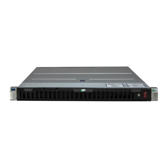
1. Product Views Front view Rear view Product construct view... -
Page 4: Reportable Materials On Sys-121H-Tnr
2. Reportable Materials on SYS-121H-TNR According to Article 8(2) and Annex VII of WEEE directive 2012/19/EU, Below materials and components should be selectively treated. Description Notes Quantity With a surface greater than 10 sq cm Printed Circuit Boards (PCB) or 2.4, 3.5, 4.2, 4.1, 7.1,8.2,... -
Page 5: Disassemble Instructions
Components, parts, and materials containing radioactive substances 3. Disassemble Instructions The intent of this document is to provide guidance to recyclers on the presence of materials and components at the product / family level, as required by the EU WEEE Directive 2012/10/EU. This document should also help direct recyclers to proper methods for removing parts and general product disassembly instructions. - Page 6 Chassis Power Supply Storage Card and CPU Chassis Chassis Enclosure Screw Air Shroud Motherboard/ Backplane/ Riser Card Cable Battery Power Supply...
- Page 7 Power Enclosure Screw and Standoff Power Supply Module Power Cable Storage Card and CPU Heat Sink Processor Solid State Drive TPM Module DIMM...
-
Page 8: Step-By-Step Disassembly Instructions
3.3 Step-by-Step Disassembly Instructions 1. Removing Cable and Chassis Top Cover 1. Use the operating system to power down the system. 2. After the system has completely shut down, disconnect the power cords from the power supply modules. 1.2 1.3 1.4 1.5 1.6 1.7 4. -
Page 9: Removing Hard Disk Drive
2. Removing Hard Disk Drive 1. Push the release button on the drive carrier, which will extend the drive bay handle 2. Use the drive bay handle to pull the drive carrier out of the chassis 3. Release clasps and post, then pull out the dummy tray 5. -
Page 10: Removing Power Supply
Description Dummy Tray Hard Drive Hard Drive Enclosure Hard Drive PCB 3. Removing Power Supply 1. Press the release tab on the failed power supply. 2. Use the handle to gently slide the power supply out the back of the chassis. 3. -
Page 11: Removing Backplane
Fan Cable Power Module PCB Capacitor 4. Removing Backplane 1. Remove the backplane two screws from the chassis Description Backplane 5. Removing Fan 1. Disconnect the chassis fan from the motherboard and Fan connector Description Cooling Fan... -
Page 12: Removing The Air Shroud And Riser Bracket
6. Removing the Air shroud and Riser Bracket Lift the air shroud out of the chassis by hand Evenly pull the top load riser bracket up and out from the system Description Air shroud Riser Bracket 7. Removing the Riser Card 1. - Page 13 3. Once the peek nuts have been loosened from the CPU socket, press the rotating wires inward to unlatch the PHM from the socket, as shown below. 4. Gently lift the PHM upward to remove it from the CPU socket. To remove the processor carrier assembly from the PHM, please follow the steps below: 5.
-
Page 14: Removing Dimm
7. Unlock the lever from its locked position and push it upwards to disengage the processor from the processor carrier, as shown below on the right. 8. Once the processor has been loosened from the carrier, carefully remove the processor from the carrier. Note: Please handle the processor carefully to avoid damaging it or its pins. -
Page 15: Removing M.2
1. Use your hands to press both release tabs on the ends of the DIMM module to unlock it. 2. Once the DIMM module is loose, remove it from the memory slot. Description DIMM 10. Removing M.2 10.1 1. Use your hand to pull out the M.2 from the motherboard Description 10.1 11. - Page 16 Description 11.1 Motherboard 11.2 Battery...
Need help?
Do you have a question about the SYS-121H-TNR and is the answer not in the manual?
Questions and answers