
Subscribe to Our Youtube Channel
Related Manuals for Gira 2111 00


Summary of Contents for Gira 2111 00
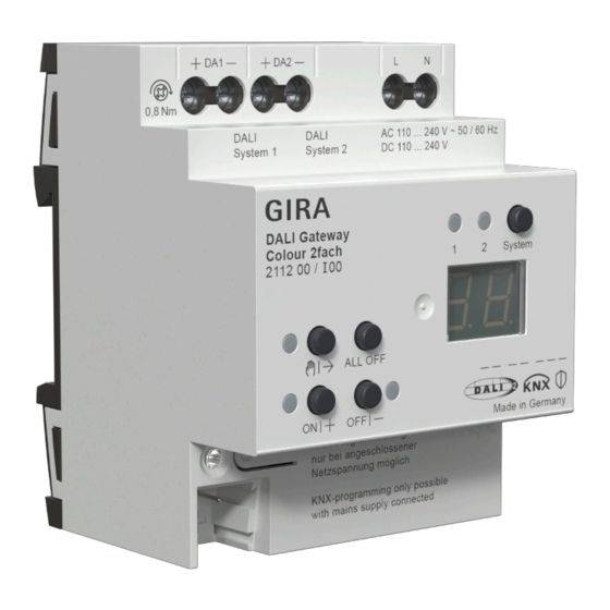
- Page 1 Operating instructions DALI gateway Colour, 1-gang Order no. 2111 00 DALI gateway Colour, 2-gang Order no. 2112 00 Product image non-binding...
-
Page 2: Table Of Contents
DALI gateway Colour, 1-gang, DALI gateway Colour, 2-gang Table of contents Safety instructions ...................... 3 Function .......................... 3 Operation .......................... 5 Information for electrically skilled persons ................ 8 Mounting and electrical connection................ 8 Commissioning ...................... 9 Appendix......................... 12 Technical data...................... 12 Troubleshooting .................... -
Page 3: Safety Instructions
The device can be updated. Firmware can be easily updated with the Gira ETS Ser- vice App (additional software). The device is KNX Data Secure capable. KNX Data Secure offers protection against manipulation in building automation and can be configured in the ETS project. - Page 4 DALI gateway Colour, 1-gang, DALI gateway Colour, 2-gang – Control of max. 2x 64 DALI devices in max. 2x 32 groups ("2-fold" device vari- ant) – Setting the colour temperature or light colour (RGB, RGBW) for luminaires with DALI Device Type 8 in accordance with IEC 62386-209 –...
-
Page 5: Operation
DALI gateway Colour, 1-gang, DALI gateway Colour, 2-gang Operation Figure 1: DALI Gateway control panel, 1fold Figure 2: DALI Gateway control panel, 2fold ǃ button – Manual operation LED ǃ – On: Continuous manual mode active LED ǃ – Flashing: Temporary manual mode is active ON|+ button –... - Page 6 DALI gateway Colour, 1-gang, DALI gateway Colour, 2-gang LED of the active DALI system lights up in manual mode or after pressing the change-over button (only with "2fold" device variant) (10) Change-over button for DALI systems 1 and 2 (only with "2fold" device vari- ant) If the display (8) shows bc (broadcast operation), all devices of a DALI system are controlled jointly.
- Page 7 DALI gateway Colour, 1-gang, DALI gateway Colour, 2-gang Operating DALI devices The device is in permanent or temporary manual operation mode. Press ǃ (1) button briefly as many times as necessary until the display (8) shows the desired DALI number. ■...
-
Page 8: Information For Electrically Skilled Persons
DALI gateway Colour, 1-gang, DALI gateway Colour, 2-gang Information for electrically skilled persons Mounting and electrical connection DANGER! Electric shock when live parts are touched. Electric shocks can be fatal. Always disconnect device before carrying out work on it. For this, switch off all cor- responding circuit breakers, secure against being switched on again and check that there is no voltage. -
Page 9: Commissioning
DALI gateway Colour, 1-gang, DALI gateway Colour, 2-gang Figure 3: DALI gateway connection example, 2fold ■ Attach the cover cap to the bus cable connection as protection against hazard- ous voltages. If the display (8) shows Er (error), an installation fault occurred that causes mains voltage to reach the DALI cable. - Page 10 DALI gateway Colour, 1-gang, DALI gateway Colour, 2-gang device types, group assignments, etc.). This is the case, for example, if a device is copied unchanged in the ETS project design or a configuration tem- plate is imported. No ETS programming is possible if no mains voltage supply is connected. Safe-state mode If the device does not work properly - for instance as a result of errors in the project design or during commissioning - the execution of the loaded application program...
- Page 11 DALI gateway Colour, 1-gang, DALI gateway Colour, 2-gang ■ Cause bus voltage failure. Master reset The master reset restores the basic device settings (physical address 15.15.255, firmware remains in place). The device must then be recommissioned with the ETS. Manual operation is possible. In secure operation: A master reset deactivates device security.
-
Page 12: Appendix
DALI gateway Colour, 1-gang, DALI gateway Colour, 2-gang Appendix Technical data KNX medium TP 256 KNX commissioning mode S mode Rated voltage KNX DC 21 ... 32 V SELV Current consumption KNX 4.5 ... 5.0 mA Connection type for bus Device connection terminal Supply Rated voltage... -
Page 13: Troubleshooting
DALI gateway Colour, 1-gang, DALI gateway Colour, 2-gang Figure 5: Clampable cable cross-sections Installation width 72 mm / 4 HP Connection mode Screw terminal Connection torque, screw terminals max. 0.8 Nm Troubleshooting Indication shows "Er", connected DALI devices have no function, no operation possible Cause: Mains voltage on DALI cable. -
Page 14: Warranty
Please submit or send faulty devices postage paid together with a fault de- scription to your responsible salesperson (specialist trade / installation company / electrical specialist trade). They will forward the devices to the Gira Service Center. Gira Giersiepen GmbH & Co. KG...
Need help?
Do you have a question about the 2111 00 and is the answer not in the manual?
Questions and answers