
Related Manuals for BCM Advanced Research MX610H


Summary of Contents for BCM Advanced Research MX610H
- Page 1 MX610H 12th/13th Gen Intel® Core™ Processors Mini-ITX Motherboard with Intel® H610E Chipset User’s Manual Ed – 04 January 2024 Part No. E2047MX6H01R...
- Page 2 Avalue Technology assumes no responsibility or liability for the use of the described product(s), conveys no license or title under any patent, copyright, or masks work rights to these products, and makes no representations or warranties that 2 MX610H User’s Manual...
- Page 3 These answers are normally a lot more detailed than the ones we can give over the phone. So please consult the user’s manual first. To receive the latest version of the user’s manual; please visit our Web site at: http://www.avalue.com.tw/ MX610H User’s Manual...
- Page 4 A product returned without proof of the purchase date is not eligible for warranty service. Write the RMA number visibly on the outside of the package and ship it prepaid to your dealer. 4 MX610H User’s Manual...
-
Page 5: Table Of Contents
2.3.21 Digital I/O header connector (JGPIO1) ..................31 2.3.22 LVDS Inverter Connector (JINV1) ....................32 2.3.23 JESPI connector (JESPI1) ......................32 2.3.24 LVDS connector (JLVDS1) ......................33 2.3.25 PS/2 KB&MS Connector (JKBMS1) ....................34 2.3.26 JSPI header connector (JSPI1) ..................... 34 MX610H User’s Manual... - Page 6 Serial Port Console Redirection ....................57 3.6.5.3.1 Console Redirection Settings (COM1) .................. 58 3.6.6 Boot ..............................59 3.6.6.1 UEFI Application Boot Priorities ....................59 3.6.7 Save & Exit ............................. 59 4. Mechanical Drawing ....................61 Mechanical Drawing ....................62 6 MX610H User’s Manual...
-
Page 7: Getting Started
1.2 Packing List Before you begin installing your single board, please make sure that the following materials have been shipped: 1 x MX610H motherboard 1 x I/O Shield MX610H User’s Manual... -
Page 8: Document Amendment History
MX610H User’s Manual 1.3 Document Amendment History Revision Date Comment December 2023 Avalue Initial Release January 2024 Avalue Update User condition suggestion 8 MX610H User’s Manual... -
Page 9: Manual Objectives
We strongly recommend that you study this manual carefully before attempting to set up MX610H or change the standard configurations. Whilst all the necessary information is available in this manual we would recommend that unless you are confident, you contact your supplier for guidance. -
Page 10: System Specifications
1 ~ 255 sec timer HW Monitor 1 x PWM FAN for CPU Smart FAN 1 x PWM FAN for System Audio Realtek® ALC897 HD Audio Codec with Auto Jack Sensing 1 x Intel® I219-LM GbE LAN PHY 10 MX610H User’s Manual... - Page 11 2 x 2*3-Pin Headers provide selections of “Ring-In”, or “12V” or “5V” on COM1&2 Ring-In/ Power and COM3&COM4 ports Select AT/ATX Select 1 x 1*3-Pin Header Clear CMOS 1 x 1*3-Pin Header ME FW Enable/Disable 1 x 1*3-Pin Header Select LVDS Backlight 1 x 1*3-Pin Header MX610H User’s Manual 11...
- Page 12 1 x Stack up dual COMs Connector Power & Connector 1 x 2*12-pin Mini‐Fit ATX-Power Connector 1 x 2*4-pin Mini‐Fit 12V ATX-Power Connector Form Factor Mini-ITX (6.7-in x 6.7-in) Certification FCC Class B, CE Note: Specifications are subject to change without notice. 12 MX610H User’s Manual...
-
Page 13: Architecture Overview-Block Diagramk Diagram
User’s Manual Arch 1.6 Architecture Overview—Block Diagramk Diagram The following block diagram shows the architecture and main components of MX610H. MX610H User’s Manual 13... - Page 14 Before you install the mainboard, study the configuration of your chassis to ensure that the mainboard fits into it. Make sure to unplug the power cord before installing or removing the mainboard. Failure to do so can cause you physical injury and damage mainboard components. 14 MX610H User’s Manual...
- Page 15 Mounting Holes Place the screws into the mounting holes indicated by the red circles to secure the mainboard to the chassis. Do not over-tighten the screws! Doing so may damage the mainboard. MX610H User’s Manual 15...
-
Page 16: Hardware Configuration
MX610H User’s Manual 2. Hardware Configuration 16 MX610H User’s Manual... -
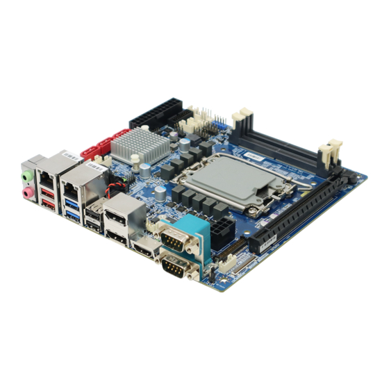
Page 17: Product Overview
User’s Manual 2.1 Product Overview MX610H User’s Manual 17... -
Page 18: Jumper And Connector List
JBKLVOL1 LVDS Backlight Power 3V/5V Select 3 x 1 header, pitch 1.25mm COM1 & COM2 3 x 2 header, pitch 2.00mm JCOMP1_2 RI/+5V/+12V Select COM3 & COM4 JCOMP3_4 3 x 2 header, pitch 2.00mm RI/+5V/+12V Select 18 MX610H User’s Manual... - Page 19 1 x Audio Dual Jack (Line-Out, Mic) 1 x 2.5GbE RJ45 + Dual USB 3.2 Conn2 Gen1 Stacked Connector 1 x GbE RJ45 + Dual USB 3.2 Gen1 Conn1 Stacked Connector 1 x Stack up USB 2.0 Connectors USB1 MX610H User’s Manual 19...
- Page 20 4 x 2 header, pitch 2.00mm JSPI1 JESPI Connector 5 x 2 header, pitch 2.00mm JESPI1 HDMI1 1 x HDMI Connector 1 x Stack up dual DisplayPort Connector 1 x Stack up dual COMs Connector JCOM1 20 MX610H User’s Manual...
-
Page 21: Setting Jumpers & Connectors
User’s Manual 2.3 Setting Jumpers & Connectors 2.3.1 Clear CMOS (JCMOS1) Normal * Clear CMOS * Default 2.3.2 Enable/disable the Intel ME F/W (JME_DIS1) Enable* Disable * Default MX610H User’s Manual 21... -
Page 22: At/Atx Power Select (Jatx1)
MX610H User’s Manual 2.3.3 AT/ATX Power Select (JATX1) ATX* * Default 2.3.4 LVDS Backlight Control Select (JLVDS_BKL1) From PCH* From ADI_AD5258BRMZ10 IC * Default 22 MX610H User’s Manual... -
Page 23: Com1/2 Ri/+5V/+12V Select (Jcomp1_2)
User’s Manual 2.3.5 COM1/2 RI/+5V/+12V Select (JCOMP1_2) +12V * Default RS232 RS422 RS485 TXD - DATA- RXD + TXD + DATA+ RXD - Ring in 5V/12V out 5V/12V out or 5V/12V out MX610H User’s Manual 23... -
Page 24: Com3/4 Ri/+5V/+12V Select (Jcomp3_4)
MX610H User’s Manual 2.3.6 COM3/4 RI/+5V/+12V Select (JCOMP3_4) +12V * Default 2.3.7 LVDS Backlight Power 3V/5V Select (JBKLVOL1) +3V* * Default 24 MX610H User’s Manual... -
Page 25: Cpu Fan Connector (Cpufan1)
User’s Manual 2.3.8 CPU fan connector (CPUFAN1) Signal +12V FAN_SENSE FAN_PWN 2.3.9 System fan connector (SYSFAN1) Signal +12V FAN_SENSE FAN_PWN MX610H User’s Manual 25... -
Page 26: System Panel Connector (Jfp1)
Signal PIN PIN Signal Reserved Reset Switch+ Power Button+ Suspend LED+ HDD LED- Power LED+ HHD LED+ 2.3.11 ATX-Power Connector (JPWR1) Signal PIN PIN Signal +3.3V +3.3V -12V +3.3V PS-ON# PWR OK 5VSB +12V +12V +3.3V 26 MX610H User’s Manual... -
Page 27: Atx-Power Connector (Jpwr2)
User’s Manual 2.3.12 12V ATX-Power Connector (JPWR2) Signal PIN PIN Signal +12V +12V +12V +12V 2.3.13 Serial Port connectors (JCOM3/4) COM3 COM4 Signal PIN PIN Signal SOUT RI/+5V/+12V MX610H User’s Manual 27... -
Page 28: Usb 2.0 Connector (Jusb1/2)
USB 2.0 Connector (JUSB1/2) Signal PIN PIN Signal USB0- USB1- USB0+ USB1+ JUSB1 JUSB2 2.3.15 USB 3.2 Gen 1 Connector (USB3) Signal PIN PIN Signal USB3.0_RX- USB3.0_RX- USB3.0_RX+ USB3.0_RX+ USB3.0_TX- USB3.0_TX- USB3.0_TX+ USB3.0_TX+ USB_D- USB_D- USB_D+ USB_D+ 28 MX610H User’s Manual... -
Page 29: Front Panel Audio Connector (Jaud1)
Front Panel Audio Connector (JAUD1) Signal PIN PIN Signal MIC_L Front Panel MIC_R Audio Detection Head Phone_R MIC Detection Sense_Send Head Phone Head Phone_L Detection 2.3.17 Amplifier connector (JAMP1) Signal AMP_ R- AMP_ R+ AMP_ L- AMP_ L+ MX610H User’s Manual 29... -
Page 30: I2C Connector (Ji2C1)
MX610H User’s Manual 2.3.18 I2C connector (JI2C1) Signal 3.3V DATA 2.3.19 Chassis Intrusion Connector (JCASE5) Signal SIO_CASEOPEN# 30 MX610H User’s Manual... -
Page 31: Smbus Connector (Jsmb1)
SMBALERT# SMBDATA SMBCLK Note: The connector is for the RD to update the Power IC firmware only 2.3.21 Digital I/O header connector (JGPIO1) Signal PIN PIN Signal N_GPO3 N_GPI3 N_GPO2 N_GPI2 N_GPO1 N_GPI1 N_GPO0 N_GPI0 3.3V MX610H User’s Manual 31... -
Page 32: Lvds Inverter Connector (Jinv1)
MX610H User’s Manual 2.3.22 LVDS Inverter Connector (JINV1) Signal +12V Enable Brightness control 2.3.23 JESPI connector (JESPI1) Signal PIN PIN Signal ESPI_HDR_ALERT0 ESPI_CLK_HDR_C ESPI_IO3_HDR_C ESPI_CS0_N ESPI_IO2_HDR_C ESPI_HDR_RESET# ESPI_IO1_HDR_C VCC3 ESPI_IO0_HDR_C 32 MX610H User’s Manual... -
Page 33: Lvds Connector (Jlvds1)
LVDS was disabled by default Default resolution: 1024x768 18/1 Default PWM Voltage: 3V (5V By jumper selection) JLVDS_BK1: *short 1-2 Brightness bar is workable under Win10 OS *short 2-3 Backlight is controlled by ADI_AD5258BRMZ10 IC via API MX610H User’s Manual 33... -
Page 34: Ps/2 Kb&Ms Connector (Jkbms1)
MX610H User’s Manual 2.3.25 PS/2 KB&MS Connector (JKBMS1) Signal KB_CLK KB_DAT MS_CLK MS_DAT 2.3.26 JSPI header connector (JSPI1) Signal PIN PIN Signal +VCCSPI SPI_CS0_HDR SPI_CLK_HDR SPI_MISO_HDR SPI_MOSI_HDR SPI_HOLD#_HDR 34 MX610H User’s Manual... - Page 35 Replacing the CPU While replacing the CPU, always turn off the power supply or unplug the power supply’s power cord from the grounded outlet first, to ensure the safety of CPU. MX610H User’s Manual 35...
- Page 36 MX610H User’s Manual CPU Installation 36 MX610H User’s Manual...
- Page 37 User’s Manual CPU cooler Installation MX610H User’s Manual 37...
- Page 38 When installing the CPU, make sure that you install a cooler to prevent overheating. If you do not have a CPU cooler, consult your vendor before turning on the computer. • The SO-DIMM slot is intended for memory modules. • Installing a DDR5 SODIMM 38 MX610H User’s Manual...
- Page 39 Place the chassis cover back on. • PCI (Peripheral Component Interconnect) Express Slot The PCI Express slot supports the PCI Express interface expansion card. • PCIe x16 Slot: SLOT1 The PCI Express x16 Gen4 Bandwidth supports up to 252 GT/s. MX610H User’s Manual 39...
- Page 40 • M.2 Slot (Key M, 2280 & 2242): M2_M1 Please install the M.2 solid-state drive (SSD) into the M.2 slot as shown below. When adding or removing expansion cards, make sure the system power is OFF. 40 MX610H User’s Manual...
- Page 41 When adding or removing expansion cards, make sure that you unplug the power supply first. Meanwhile, read the documentation for the expansion card to configure any necessary hardware or software settings for the expansion card, such as jumpers, switches or BIOS configuration. MX610H User’s Manual 41...
-
Page 42: Bios Setup
MX610H User’s Manual 3.BIOS Setup 42 MX610H User’s Manual... -
Page 43: Introduction
If you do not press the keys at the correct time and the system does not boot, an error message will be displayed and you will again be asked to. Press F1 to Continue, DEL to enter SETUP MX610H User’s Manual 43... -
Page 44: Using Setup
Note: Some of the navigation keys differ from one screen to another. To Display a Sub Menu Use the arrow keys to move the cursor to the sub menu you want. Then press <Enter>. A “” pointer marks all sub menus. 44 MX610H User’s Manual... -
Page 45: Getting Help
BIOS Vendor and your systems manufacturer to provide the absolute maximum performance and reliability. Even a seemingly small change to the chipset setup has the potential for causing you to use the override. MX610H User’s Manual 45... -
Page 46: Bios Setup
Note: The BIOS setup screens shown in this chapter are for reference purposes only, and may not exactly match what you see on your screen. Visit the Avalue website (www.avalue.com.tw) to download the latest product and BIOS information. 46 MX610H User’s Manual... -
Page 47: Advanced Bios Setup
This setting is to set the Num Lock status when the system is powered on. [On] Turn on the Num Lock key when the system is powered on. [Off] Allow users to use the arrow keys on the numeric keypad. MX610H User’s Manual 47... -
Page 48: Cpu Configuration
C States This setting controls the C-States (CPU Power states). [Enabled] Detects the idle state of system and reduce CPU power consumption accordingly. [Disabled] Disables this function. 48 MX610H User’s Manual... -
Page 49: Supoer Io Configuration
Watch Dog Timer You can enable the system watchdog timer, a hardware timer that generates a reset when the software that it monitors does not respond as expected each time the watchdog polls it. MX610H User’s Manual 49... -
Page 50: H/W Monitor (Pc Health Status)
Smart CPUFAN/ SYSFAN Target This setting enables/ disables the Smart Fan function. Smart Fan is an excellent feature which will adjust the system fan speed automatically depending on the current system temperature, avoiding the situation of the system overheating. 50 MX610H User’s Manual... -
Page 51: Network Stack Configuration
Press “+” or “-” on your keyboard to change the value. The default setting is 0. Media detect count This option specifies the number of times media will be checked. Press “+” or “-” on your keyboard to change the value. The default setting is 1. MX610H User’s Manual 51... -
Page 52: Usb Configuration
Set the amount of time that the POST (Power On Self Test) will wait for the USB mass storage device to be detected. Device power-up delay Set the maximum time that a USB device will wait before reporting itself to the host controller. USB Power Control This setting enables/disables USB Ports. 52 MX610H User’s Manual... -
Page 53: Pci/ Pcie Device Configuration
This setting enables/disables the onboard LAN 1/2 controllers. 3.6.2.8 GPIO Group Configuration GPO0 ~ GPO3 These settings control the operation mode of the specified GPIO. 3.6.3 Chipset DVMT Pre-Allocated This setting specifies the pre-allocated graphics memory size for DVMT (Dynamic MX610H User’s Manual 53... -
Page 54: Power
Other components may remain powered so the computer can “wake” on input from the keyboard, clock, modem, LAN, or USB device. OnChip USB The item allows the activity of the OnChip USB device to wake up the system from S4/ S5 sleep state. 54 MX610H User’s Manual... -
Page 55: Security
Administrator Password controls access to the BIOS Setup utility. User Password User Password controls access to the system at boot and to the BIOS Setup utility. Chassis Intrusion Detects whether the chassis has been opened when used with the Chassis Intrusion header. MX610H User’s Manual 55... -
Page 56: Trusted Computing
Physical Presence Spec Version This settings show the Physical Presence Spec Version. TPM 2.0 Interface Type This setting shows the TPM 2.0 Interface Type. Device Select Select your TPM device through this setting. 56 MX610H User’s Manual... -
Page 57: Pch-Fw Configuration
Console Redirection operates in host systems that do not have a monitor and keyboard attached. This setting enables/disables the operation of console redirection. When set to [Enabled], BIOS redirects and sends all contents that should be displayed MX610H User’s Manual 57... -
Page 58: Console Redirection Settings (Com1)
VT-UTF8 Combo Key Support This setting enables/disables the VT-UTF8 combination key support for ANSI/VT100 terminals. Recorder Mode, Resolution 100x31 These settings enable/disable the recorder mode and the resolution 100x31. Putty KeyPad 58 MX610H User’s Manual... -
Page 59: Boot
This setting allows users to set the system boot order. 3.6.7 Save & Exit Save Changes and Reset Save changes to CMOS and reset the system. Discard Changes and Exit Abandon all changes and exit the BIOS menu. MX610H User’s Manual 59... - Page 60 Restore the user’s default profile. Launch EFI Shell from filesystem device This setting helps to launch the EFI Shell application from one of the available file system devices. AMIFWUpdate Launch AMIFWUpdate for updating the BIOS. 60 MX610H User’s Manual...
-
Page 61: Mechanical Drawing
User’s Manual 4. Mechanical Drawing MX610H User’s Manual 61... -
Page 62: Mechanical Drawing
MX610H User’s Manual 4.1 Mechanical Drawing Unit: mm 62 MX610H User’s Manual... - Page 63 User’s Manual Unit: mm MX610H User’s Manual 63...
Need help?
Do you have a question about the MX610H and is the answer not in the manual?
Questions and answers