
Related Manuals for BCM Advanced Research MX87QD


Summary of Contents for BCM Advanced Research MX87QD
- Page 1 MX87QD Ver 1.0 User’s Manual Intel® Q87 Mini ITX Motherboard supports 22nm Intel® Core™ i7/i5/i3 generation Desktop Processors (Haswell Platform)
-
Page 2: Table Of Contents
1.8.6 Digital IO Connector (JDIO1) ..................41 1.8.7 PARALLEL PORT Connector (LPT1) ................42 1.8.8 PS/2 KB/MS (KBMS1) ....................42 1.8.9 Low-voltage differential signalling Connector(JLVDS1) ..........42 1.8.10 LCD Inverter Connector (JBKL1) ................44 1.8.11 USB connectors (USB56, USB78, USB910) .............. 44 2 MX87QD User’s Manual... - Page 3 2.4.12 Intel RC Driver Version Detail ..................74 2.5 Chipset ........................75 2.5.1 PCH-IO Configuration ....................76 2.5.2 System Agent (SA) Configuration ................82 2.6 Boot ........................... 87 2.7 Security ........................89 2.8 Save & Exit ....................... 90 AppendixA ........................ 91 MX87QD User’s Manual 3...
- Page 4 If you encounter technical problems with the product, contact a qualified service technician or your retailer. The symbol of the crossed out wheeled bin indicates that the product (electrical and electronic equipment) should not be placed in municipal waste. Check local regulations for disposal of electronic products. 4 MX87QD User’s Manual...
- Page 5 If a problem arises with your system and no solution can be obtained from the user’s manual, please contact your place of purchase or local distributor. Alternatively, please try the following help resources for further guidance. Visit the BCM Advanced Research website: http://www.BCMCOM.com...
- Page 6 Example: <Ctrl>+<Alt>+<D> Command Means that you must type the command exactly as shown, then supply the required item or value enclosed in brackets Example: At the DOS prompt, type the command line: afudos /i[filename] afudos /iP5P800VM.ROM 6 MX87QD User’s Manual...
- Page 7 MX87QD User’s Manual Packing List Before you begin installing your single board, please make sure that the following materials have been shipped: 1 x MX87QD Mini-ITX Main board 1 x Dual COM cables 2 x SATA cables ...
- Page 8 MX87QD User’s Manual Revision History Revision Revision History Date V1.0 First release version 2013/06 8 MX87QD User’s Manual...
- Page 9 4 x COM Port (pin header) 10 x USB Port (4 x USB3.0, 6 x USB2.0) 4 x SATA 6.0 Gp/s 1x LPT (pin header) 1x PS2 MS/KB (Optional) Others 16 Bit GPIO (DIO) / Front audio / TPM 1.2 MX87QD User’s Manual 9...
- Page 10 Max. Resolution 2048 x 1536 bpp(@ 75Hz) on Board Dual Display Port on board on board, via level shifter Audio Audio Codec Realtek® ALC892, 5.1 +2 with two independent Streaming Audio Interface Line in, Line Out, Mic-in 10 MX87QD User’s Manual...
- Page 11 Minimum output rating @150W recommended. Operating Temperature 0~60°C (32~140°F) Operating Humidity 0%~90% relative humidity, non-condensing Size (L x W) 6.7" x 6.7" (170 mm x 170 mm) Weight 0.88 lbs (0.40 Kg) * Specifications are subject to change without notice. MX87QD User’s Manual 11...
- Page 12 MX87QD User’s Manual Block Diagram 12 MX87QD User’s Manual...
- Page 13 MX87QD User’s Manual This chapter describes the motherboard features and the new technologies it supports. Product Introduction MX87QD User’s Manual 13...
-
Page 14: Product Highlights
• DirectX® 11.1 & Open GL 3.2 let you enjoy awesome graphics performance, stunning 3D visual effect and dynamic interactivity • Memory support, integrated low voltage DDR3 memory controller • Operating system support: - Microsoft 14 MX87QD User’s Manual... - Page 15 - Enables faster and higher quality video editing, recording and sharing • I/O - PCI Express® x 16 - Four SATA ports (Gen 3.0, 6Gb/s) support RAID 0,1, 5, 10 - Gigabit Ethernet Media Access Controller (GbE MAC) MX87QD User’s Manual 15...
-
Page 16: Before You Proceed
Before you install or remove any component, ensure that the ATX power supply is switched off or the power cord is detached from the power supply. Failure to do so may cause severe damage to the motherboard, peripherals, and/or components. 16 MX87QD User’s Manual... -
Page 17: Motherboard Overview
Place four (4) screws into the holes indicated by circles to secure the motherboard to the chassis. Do not over tighten the screws! Doing so can damage the motherboard. Place this side towards the rear of the chassis. MX87QD User’s Manual 17... -
Page 18: Motherboard Layout
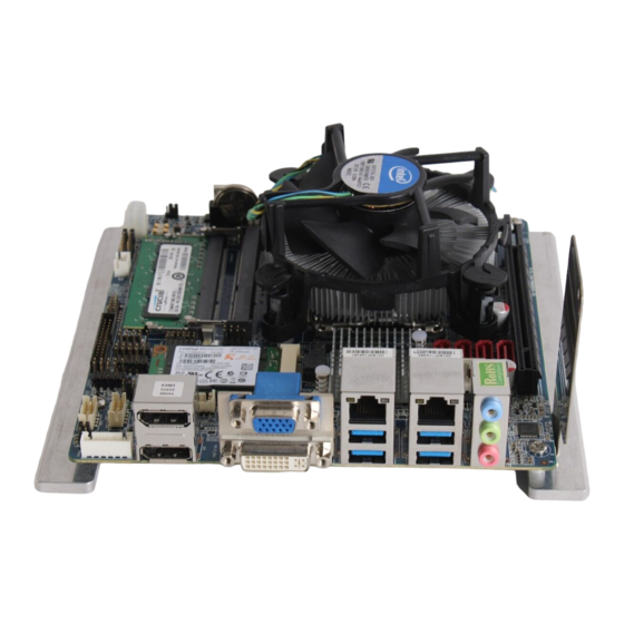
1.3.3 Motherboard Layout 1.3.4 Layout Content List Slots & socket Label Function Note Page LGA1150 LGA1150 socket DIMMA1 204-pin DDR3 SODIMM Slot A1 DIMMB1 204-pin DDR3 SODIMM Slot B1 PCIEX16 PCIe x16 Slot MINI_CARD Mini-PCIe Slot 18 MX87QD User’s Manual... - Page 19 Dual Link DVI-D; 24 pins LAN1_USB12 RJ-45 Ethernet Connector x 1 USB 3.0 Connector x 2 LAN2_USB34 RJ-45 Ethernet Connector x 1 USB 3.0 Connector x 2 AUDIO1 Line-in Port, Line-out Port, 5.1 Channel Audio I/O (3 jacks) Microphone Port, MX87QD User’s Manual 19...
-
Page 20: Internal Connector
Front Panel Audio Connector 5 x 2 header, pitch 2.54mm JAMP1 Amplifier Connector 4 x 1 header, pitch 2.54mm SATA1~4 Serial ATA Connectors 1~4 7-pin header SATAPW1~2 SATA Power Connectors 1~2 4 x 1 wafer, pitch 2.54mm 20 MX87QD User’s Manual... -
Page 21: Central Processing Unit (Cpu)
If you purchased a separate CPU heatsink and fan assembly, make sure that you have properly applied Thermal Interface Material to the CPU heatsink or CPU before you install the heatsink and fan assembly. MX87QD User’s Manual 21... -
Page 22: Installing The Cpu
2. Press the load lever with your thumb (A), then move it to the left (B) until it is released from the retention tab. Retention tab Load lever To prevent damage to the socket pins, do not remove the PnP cap unless you are installing a CPU. 22 MX87QD User’s Manual... - Page 23 (A) until it snaps into the retention tab. The CPU fits in only one correct orientation. DO NOT force the CPU into the socket to prevent bending the connectors on the socket and damaging the CPU! MX87QD User’s Manual 23...
-
Page 24: Installing The Cpu Heatsink And Fan
Motherboard hole Orient the heatsink and fan assembly such that the CPU fan cable is closest to the CPU fan connector. Make sure each fastener is oriented as shown, with the narrow groove directed outward. 24 MX87QD User’s Manual... - Page 25 These are not jumpers! DO NOT place jumper caps on the fan connectors. 1.4.3 Uninstalling the CPU Heatsink and Fan To uninstall the CPU heatsink and fan: 1. Disconnect the CPU fan cable from the connector on the motherboard. 2. Rotate each fastener counterclockwise MX87QD User’s Manual 25...
- Page 26 MX87QD User’s Manual 3. Pull up two fasteners at a time in a diagonal sequence to disengage the heatsink and fan assembly from the motherboard. 4. Carefully remove the heatsink and fan assembly from the motherboard. 26 MX87QD User’s Manual...
-
Page 27: System Memory
A DDR3 SODIMM module has the same physical dimensions as a DDR2 SODIMM but has a 204-pin footprint compared to the 240-pin DDR2 DIMM. DDR3 SODIMMs are notched differently to prevent installation on a DDR2 SODIMM socket. The following figure illustrates the location of the sockets: 204-Pin DDR3 SODIMM sockets MX87QD User’s Manual 27... -
Page 28: Memory Configurations
3. Align the notch key on the module with the rib on the slot. 4. Firmly press the modules into the socket which will automatically snap into the mounting notch. Do not force the SODIMM module in with extra force as the DIMM module only fits in one direction. 28 MX87QD User’s Manual... -
Page 29: Removing A Ddr3 Sodimm
The DDR3 SODIMM sockets do not support DDR/DDR2 SODIMMs. DO NOT install DDR/DDR2 SODIMMs to the DDR3 SODIMM socket. 1.5.4 Removing a DDR3 SODIMM 1. Press the two ejector tabs on the slot outward simultaneously, and then pull out the DIMM module. MX87QD User’s Manual 29... -
Page 30: Expansion Card
4. Align the card connector with the slot and press firmly until the card is completely seated on the slot. 5. Secure the card to the chassis with the screw you removed earlier. 6. Replace the system cover. 30 MX87QD User’s Manual... -
Page 31: Configuring An Expansion Card
3. Install the software drivers for the expansion card. 1.6.2.1 PCI Express x16 slot This motherboard supports one PCI Express x16 slot that complies with the PCI Express specifications. The following figure shows a graphics card installed on the PCI Express x16 slot. MX87QD User’s Manual 31... -
Page 32: Minipci Express Slot
Card Rev. 1.2 specifications . The figure below shows the type of full size MiniPCIe / SSD card that can be installed on the top MiniPCI express slot. Half size MiniPCIe card can be installed on the bottom MiniPCI express slot. 32 MX87QD User’s Manual... -
Page 33: Jumpers
You do not need to clear the RTC when the system hangs due to overclocking. For system failure due to overclocking, use the C.P.R. (CPU Parameter Recall) feature. Shut down and reboot the system so the BIOS can automatically reset parameter settings to default values. MX87QD User’s Manual 33... -
Page 34: At/Atx Power Mode Select (Pson1)
This jumper allows you to select ATX Mode or AT Mode. ATX MODE (Default) AT MODE AT Mode: When DC-In power is applied, system will power on automatically. ATX Mode: Power button is required to power on system. 1.7.3 Chassis Intrusion Connector (JCASE1) 34 MX87QD User’s Manual... -
Page 35: Com1/Com2, Com3/Com4 Ri/+5V/+12V Select (Jcompwr1, Jcompwr2)
MX87QD User’s Manual 1.7.4 COM1/COM2, COM3/COM4 RI/+5V/+12V Mode Select (JCOMPWR1, JCOMPWR2) RI (Default) +12V Note: COM Port 1 & 2 Mode select are shared via JCOMPWR1. COM Port 3& 4 Mode select are shared via JCOMPWR2. MX87QD User’s Manual 35... -
Page 36: M-Sata/Mini Pcie Selection (Jmsatasw1)
MX87QD User’s Manual 1.7.5 M-SATA/mini PCIe Select (JMSATASW1) M-SATA Mini-PCIe (Default) 1.7.5 DC-In Power Source Select (JPSEL1) DC-In: 16V - 24V DC-In: 12V (Default) 36 MX87QD User’s Manual... -
Page 37: Connectors
6. Line Out port (lime). This port connects a headphone or a speaker. In 4-channel, 6-channel, and 8-channel configuration, the function of this port becomes Front Speaker Out. 7. Microphone port (pink). This port connects a microphone. 10. DVI Port Dual Link DVI-D, 24-Pin MX87QD User’s Manual 37... -
Page 38: Cpu And System Fan Connectors (Cpu_Fan 1,Sys_ Fan1)
Do not forget to connect the fan cables to the fan connectors. Insufficient air flow inside the system may damage the motherboard components. These are not jumpers! DO NOT place jumper caps on the fan connectors. 38 MX87QD User’s Manual... -
Page 39: System Panel (F_Panel1)
Hard Disk Drive Activity LED (Pin 1-3 HDLED) This 2-pin connector is for the HDD Activity LED. Connect the HDD Activity LED cable to this connector. The IDE LED lights up or flashes when data is read from or written to the HDD. MX87QD User’s Manual 39... -
Page 40: Dc-In Power Connectors (Atx12V1)
The system may become unstable or may not boot up if the power is inadequate. Make sure that your power supply unit (PSU) can provide at least the minimum power required by your system. 40 MX87QD User’s Manual... -
Page 41: Serial Port Connectors (Com1, Com2, Com3, Com4)
These connectors are for a serial (COM) port. Connect the serial port module cable to this connector, and then install the module to a slot opening at the back of the system chassis. 1.8.6 Digital IO Connector (JDIO1) This connector is for 8-bit General purpose I/O function. JDIO1 MX87QD User’s Manual 41... -
Page 42: Parallel Port Connector (Lpt1)
MX87QD User’s Manual 1.8.7 PARALLEL PORT Connector (LPT1) LPT1 1.8.8 Keyboard / Mouse Connector (KBMS1) The connector is for PS2 Keyboard and Mouse. 42 MX87QD User’s Manual... -
Page 43: Low-Voltage Differential Signalling Connector(Jlvds1)
(Hirose. 40P 1.25mm 90D SMD DF13-40DP-1.25V(91)) Signal Pin Pin Signal +12V +12V LVDS1_CLKN LVDS0_CLKN LVDS1_CLKP LVDS0_CLKP LVDS1_N3 LVDS1_N2 LVDS1_P3 LVDS1_P2 LVDS1_N1 LVDS1_N1 LVDS1_P1 LVDS1_P0 JLVDS1 LVDS0_N3 LVDS0_N2 LVDS0_P3 LVDS0_P2 LVDS0_N1 LVDS0_N0 LVDS0_P1 LVDS0_P0 SC_DDC SD_DDC +3.3V +3.3V MX87QD User’s Manual 43... -
Page 44: Lcd Inverter Connector (Jbkl1)
These USB connectors comply with USB 2.0 specification that supports up to 480 Mbps connection speed. USB56, USB78, USB910 44 MX87QD User’s Manual... -
Page 45: Audio Mic.-In & Line-Out Connector (F_Audio1)
I/O module cable to this connector. FP_AUDIO1 For motherboards with the optional HD Audio feature, we recommend that you connect a high-definition front panel audio module to this connector to avail of the motherboard’s high‑definition audio capability. 1.8.13 Amplifier Connector (JAMP_1) MX87QD User’s Manual 45... -
Page 46: Serial Ata Connector (Sata1, Sata2,Sata3,Sata4)
Connect the right-angle side of SATA signal cable to SATA device. Or you may connect the right-angle side of SATA cable to the onboard SATA port to avoid mechanical conflict with large graphics cards. 1.8.15 Serial ATA Power Connector SATAPW1, SATAPW2 46 MX87QD User’s Manual... - Page 47 MX87QD User’s Manual This chapter tells how to change the system settings through the BIOS Setup menus. Detailed descriptions of the BIOS parameters are also provided. MX87QD User’s Manual 47...
-
Page 48: Bios Setup Program
The BIOS setup screens shown in this section are for reference purposes only, and may not exactly match what you see on your screen. Visit the system builder’s website to download the latest BIOS file for this motherboard 48 MX87QD User’s Manual... -
Page 49: Legend Box
<F9> to load the optimal default values. While moving around through the Setup program, note that explanations appear in the Item Specific Help window located to the right of each menu. This window displays the help text for the currently highlighted field. MX87QD User’s Manual 49... -
Page 50: Bios Menu Screen
To access the menu items, press the up/down/right/left arrow key on the keyboard until the desired item is highlighted, then press [Enter] to open the specific menu. 50 MX87QD User’s Manual... -
Page 51: Main Setup
Use this menu for basic system configurations, such as time, date etc. BIOS Information Displays the auto-detected BIOS information. System Date The date format is <Date>,<Month>,<Day>,<Year>. System Time The time format is <Hour>,<Minute>,<Second>. MX87QD User’s Manual 51... -
Page 52: Advanced Bios Setup
The Advanced BIOS Setup screen is shown below. The sub menus are described on the following pages. Take caution when changing the settings of the Advanced menu items. Incorrect field values can cause the system to malfunction. 52 MX87QD User’s Manual... -
Page 53: Pci Subsystem Setting
The Configuration options are [32 PCI Bus Clocks] [64 PCI Bus Clocks] [96 PCI Bus Clocks] [128 PCI Bus Clocks] [160 PCI Bus Clocks] [32 PCI Bus Clocks] [192 PCI Bus Clocks] [224 PCI Bus Clocks] [248 PCI Bus Clocks] MX87QD User’s Manual 53... -
Page 54: Acpi Settings
Allows you to determine whether to invoke VGA BIOS POST on S3/STR resume. Configuration options: [Disabled] [Enabled] Resume On RTC Alarm [Disable] Enable or disable system wake on alarm even. When enabled, system will wake upon the hr/min/sec specified. Configuration options: [Disabled] [Enabled] 54 MX87QD User’s Manual... -
Page 55: Trusted Computing
MX87QD User’s Manual 2.4.3 Trusted computing Trusted computing (TPM) settings. TPM configuration Security Device SUPPORT [Disabled] Enable or disable TPM support. Configuration options: [Disabled] [Enabled] Current Status Information Displays the TPM status information [SUPPORT TURNED OFF] MX87QD User’s Manual 55... -
Page 56: Cpu Configuration
Select the numbers of cores in each processor package. Configuration options: [All] [1] [2] [3] It depends on each CPU type. Intel Virtualization Technology [Enabled] When enable, a VMM can utilize the additional hardware capabilities provided by Vanderpool Technology. Configuration options: [Disabled] [Enabled] 56 MX87QD User’s Manual... - Page 57 Use this to enable or disable CPU C6 (ACPI C3) report to OS. Configuration options: [Disabled] [Enabled] CPU C7 State Support [Disabled] Use this to enable or disable CPU C7 report to OS. Configuration options: [Disabled] [Enabled] MX87QD User’s Manual 57...
-
Page 58: Sata Configuration
C6/C7 state is disabled, the next lowest power state will be C3 (Deep Sleep Mode) which should be enabled. 2.4.5 SATA Configuration Serial-ATA Controller(s) [Enable] Enabled/Disabled Serial-ATA Controller 0 Configuration options: [Disabled] [Enabled] SATA Mode [IDE] Support IDE, AHCI or RAID mode Configuration options: [Disable][IDE][AHCI][RAID] 58 MX87QD User’s Manual... -
Page 59: Pch-Fw Configuration
MX87QD User’s Manual 2.4.6 PCH-FW Configuration MX87QD User’s Manual 59... -
Page 60: Amt Configuration
MX87QD User’s Manual 2.4.7 AMT Configuration 60 MX87QD User’s Manual... -
Page 61: Usb Configuration
Display how many devices are connected. Legacy USB Support [Enabled] Enables Legacy USB support. AUTO option disables legacy support if no USB devices are connected. DISABLE option will keep USB devices available only for EFI applications. Configuration options: [Enabled] [Disabled][Auto] MX87QD User’s Manual 61... -
Page 62: Nct6106D Super Io Configuration
MX87QD User’s Manual 2.4.9 NCT6106D Super IO Configuration System Super IO Chip Parameters. Super IO Configuration Super IO Chip [NCT6106D] 62 MX87QD User’s Manual... - Page 63 Configuration options: [Auto] [IO=3F8h; IRQ=4] [IO=3F8h; IRQ=3, 4, 5, 6, 7, 10, 11, 12] [IO=2F8h; IRQ=3, 4, 5, 6, 7, 10, 11, 12] [IO=3E8h; IRQ=3, 4, 5, 6, 7, 10, 11, 12] [IO=2E8h; IRQ=3, 4, 5, 6, 7, 9. 10, 11, 12] MX87QD User’s Manual 63...
- Page 64 Configuration options: [Auto] [IO=2F8h; IRQ=3] [IO=3F8h; IRQ=3, 4, 5, 6, 7, 10, 11, 12] [IO=2F8h; IRQ=3, 4, 5, 6, 7, 10, 11, 12] [IO=3E8h; IRQ=3, 4, 5, 6, 7, 10, 11, 12] [IO=2E8h; IRQ=3, 4, 5, 6, 7, 10, 11, 12] 64 MX87QD User’s Manual...
- Page 65 Configuration options: [Auto] [IO=3E8h; IRQ=5] [IO=3E8h; IRQ=3, 4, 5, 6, 7, 10, 11, 12] [IO=2E8h; IRQ=3, 4, 5, 6, 7, 10, 11, 12] [IO=2E0h; IRQ=3, 4, 5, 6, 7, 10, 11, 12] [IO=2F0h; IRQ=3, 4, 5, 6, 7, 10, 11, 12] MX87QD User’s Manual 65...
- Page 66 Configuration options: [Auto] [IO=C88h; IRQ=5] [IO=3E8h; IRQ=3, 4, 5, 6, 7, 10, 11, 12] [IO=2E8h; IRQ=3, 4, 5, 6, 7, 10, 11, 12] [IO=2E0h; IRQ=3, 4, 5, 6, 7, 10, 11, 12] [IO=2F0h; IRQ=3, 4, 5, 6, 7, 10, 11, 12] 66 MX87QD User’s Manual...
- Page 67 Use this item to enable or disable the onboard parallel port. Configuration options: [Disabled] [Enabled] Change Settings [Auto] Use this item to select an optional setting for Super IO device. Configuration Options : [Auto] [IO=378h; IRQ=7] [IO=378h; IRQ=5,6,7,9,10,11,12] [IO=278h; IRQ=5,6,7,9,10,11,12] [IO=3BCh; IRQ=5,6,7,9,10,11,12] MX87QD User’s Manual 67...
- Page 68 [EPP-1.7 and SPP Mode] [ECP Mode] [ECP Mode and EPP-1.9 Mode] [ECP Mode and EPP-1.7 Mode] 2.4.9.6 Watch Dog Configuration Watch Dog Timer Use this item to enable/disable Watch Dog Timer Configuration options: [Disabled] [Enabled] 68 MX87QD User’s Manual...
- Page 69 Configuration options: [RS232] [RS485 Half Duplex] [RS485/RS422 Full Duplex] Chassis Opened Warning Configuration options: [Disabled] [Enabled] GPIO Group Control [Disabled] Configure the digital GPIO pins Configuration options: [Disabled] [Enabled] Configuration options: [Input] [Output low] [Output high] MX87QD User’s Manual 69...
-
Page 70: Nct6106D Hardware Monitor
MX87QD User’s Manual 2.4.10 NCT6106D Hardware Monitor PC Health Status Display system health status 70 MX87QD User’s Manual... - Page 71 MX87QD User’s Manual 2.4.10.1 Smart Fan Smart Fan Function [Enable] Configuration options: [Disabled] [Enabled] MX87QD User’s Manual 71...
- Page 72 Configuration options: [Disable] [40 C] [45 C] [50 C] [55 C] [60 C] [65 C] [70 C] CPU MIN.FAN Speed(%) [62.5%] Set minimum CPU fan speed Configuration options: [12.5%] [25%] [37.5%] [50%] [62.5%] [75%] [87.5%] 72 MX87QD User’s Manual...
-
Page 73: Option Rom Policy
2.4.11 Option ROM Policy Launch Storage OpROM Enable or Disable Boot Option For Legacy Mass Storage Devices with Option ROM Configuration options: [Disabled] [Enabled] Other PCI Device ROM priority Configuration options: [UEFI OpROM] [Legacy OpROM] MX87QD User’s Manual 73... -
Page 74: Intel Rc Driver Version Detail
MX87QD User’s Manual 2.4.12 Intel RC Driver Version Detail 74 MX87QD User’s Manual... -
Page 75: Chipset
MX87QD User’s Manual 2.5 Chipset MX87QD User’s Manual 75... -
Page 76: Pch-Io Configuration
Enable/Disable LAN1 boot option for legacy network devices. Configuration options: [Disabled] [Enabled] LAN2 Controller [Enable] Enable/Disable LAN1 Controller Configuration options: [Disabled] [Enabled] LAN2 Option-ROM [Disable] Enable/Disable LAN2 boot option for legacy network devices. Configuration options: [Disabled] [Enabled] 76 MX87QD User’s Manual... - Page 77 Restore AC Power Loss [Power Off] Specify what state to go to when power is re-applied after a power failure(G3 state). Configuration options: [Power Off] [Power On] [Last state] Amplifier GAIN(db) [15.3db] Setting Amplifier GAIN Configuration options:[15.3db][21.2db][27.2db][31.8db] MX87QD User’s Manual 77...
- Page 78 MX87QD User’s Manual 2.5.1.1 PCI Express Configuration PCI Express Root Port 1 PCI Express Root Port 5 78 MX87QD User’s Manual...
- Page 79 Control ASPM support for the PEG Device. This has no effect if PEG is not the currently active device. Configuration options: [Disabled] [ASPM L0s] [ASPM L1] [ASPM L0sL1] [Auto] PCIe Speed [Auto] Configuration options: [Auto][Gen1][Gen2] Detect Non-Compliance Device [Disabled] Configuration options:[Enable][Disable] MX87QD User’s Manual 79...
- Page 80 Control ASPM support for the PEG Device. This has no effect if PEG is not the currently active device. Configuration options: [Disabled] [ASPM L0s] [ASPM L1] [ASPM L0sL1] [Auto] PCIe Speed [Auto] Configuration options: [Auto][Gen1][Gen2] Detect Non-Compliance Device [Disabled] Configuration options:[Enable][Disable] 80 MX87QD User’s Manual...
- Page 81 MX87QD User’s Manual 2.5.1.2 USB Configuration USB3.0 Support [Enabled] Enable/Disable USB 3.0 support Configuration options: [Disabled] [Enabled] USB ports per-port disable cont [Disabled] Configuration options: [Disabled] [Enabled] MX87QD User’s Manual 81...
-
Page 82: System Agent (Sa) Configuration
MX87QD User’s Manual 2.5.2 System Agent (SA) Configuration VT-d [Enabled] Set VT-d Enable or Disable Configuration options: [Disabled] [Enabled] 82 MX87QD User’s Manual... - Page 83 Select DVMT Pre-Allocated (Fixed) graphics memory size used by the internal graphics device. Configuration options: [32M]~[512M] DVMT Total Graphics Mem [256M] Select DVMT total graphics memory size used by the internal graphics device. Configuration options: [128M][256M][MAX] MX87QD User’s Manual 83...
- Page 84 Secondary booty display selection will appear based on your selection. VGA modes will be supported only on primary display. Configuration options: [VBIOS Default][CRT][DVI][LVDS] LCD Panel Type Select Select LCD Panel resolution LVDS Brightness Control [30] Configuration options:[1]~[63] 84 MX87QD User’s Manual...
- Page 85 To enable/Disable the PEG slot. Configuration options:[Auto][Enable][Disable] PEG ASPM [Auto] Control ASPM support for the PEG Device. This has no effect if PEG is not the currently active device. Configuration options: [Disabled] [Auto] [ASPM L0s] [ASPM L1] [ASPM L0sL1] MX87QD User’s Manual 85...
- Page 86 MX87QD User’s Manual 2.5.2.3 Memory Information Memory Information Display Memory Information 86 MX87QD User’s Manual...
-
Page 87: Boot
Setup Prompt Timeout [1] Number of seconds to wait for setup activation key. 65535(0xFFFF) means indefinite waiting. Bootup NumLock State [On] Select the keyboard NumLock state Configuration options: [On] [Off] Customer Logo [Disable] Configuration options: [Disable] [Enable] MX87QD User’s Manual 87... - Page 88 MX87QD User’s Manual UEFI Boot Drive BBS Priorities Select the system boot order. Configuration options: [Built-in EFI Shell][Disabled] 88 MX87QD User’s Manual...
-
Page 89: Security
MX87QD User’s Manual 2.7 Security Administrator Password Set setup Administrator Password User Password Set User Password MX87QD User’s Manual 89... -
Page 90: Save & Exit
Save changes and Exit Exit system setup after saving the changes. Discard changes and Exit Exit system setup without saving the changes. Load Optimized Defaults Restore/Load default values for all the setup option. 90 MX87QD User’s Manual... -
Page 91: Appendixa
IoWrite8 (NCT6106D_CONFIG_INDEX , NCT6106D_CONFIG_MODE_ENTER_VALUE); void SIOConfigExit () IoWrite8 (NCT6106D_CONFIG_INDEX , NCT6106D_CONFIG_MODE_EXIT_VALUE); void Oem_DIO_Init ( IN SETUP_DATA *SetupData UINT8 InputValue=0; //Default output low UINT8 OutputValue=0; UINT8 Data8=0; if(SetupData->OemGPIOControl == 0x00) //Check "GPIO Group Control" Enable/Disable InputValue =0xFF; else MX87QD User’s Manual 91... - Page 92 OutputValue |= 0x08; if(SetupData->OemDIOP4 == 0x00){ InputValue |= 0x10; } else if (SetupData->OemDIOP4 == 0x01) { OutputValue |= 0x10; if(SetupData->OemDIOP5 == 0x00){ InputValue |= 0x20; } else if (SetupData->OemDIOP5 == 0x01) { OutputValue |= 0x20; if(SetupData->OemDIOP6 == 0x00){ 92 MX87QD User’s Manual...
- Page 93 } else if (SetupData->OemDIOP7 == 0x01) { OutputValue |= 0x80; SIOConfigEnter(); IoWrite8 (NCT6106D_CONFIG_INDEX , 0x07); //Enter LDN7 IoWrite8 (NCT6106D_CONFIG_DATA , 0x07); IoWrite8(NCT6106D_CONFIG_INDEX, 0xE4); //GPIO1 Input/Output reg. IoWrite8(NCT6106D_CONFIG_DATA, InputValue); IoWrite8(NCT6106D_CONFIG_INDEX, 0xE5); //GPIO1 Data reg. IoWrite8(NCT6106D_CONFIG_DATA, OutputValue); SIOConfigExit(); MX87QD User’s Manual 93...
Need help?
Do you have a question about the MX87QD and is the answer not in the manual?
Questions and answers