
Related Manuals for BCM Advanced Research MX370QD


Summary of Contents for BCM Advanced Research MX370QD
- Page 1 MX370QD Intel® Q370 support 8 generation Core™ i7/ i5 /i3, Pentium, Celeron CPU Mini-ITX Motherboard User’s Manual Ver. 1.0...
-
Page 2: Table Of Contents
1.7.1 Rear panel connectors ........................... 29 1.7.2 CPU and System fan connectors (CPU_FAN1, SYS_FAN1) ..............30 1.7.3 System Panel (F_PANEL1) ........................31 1.7.4 DC-In power connectors (ATX12V1) ..................... 32 1.7.5 Serial Port connectors (COM1~2) ......................33 2 MX370QD User’s Manual... - Page 3 2.4.12 Compatibility Support Module Configuration ..................63 2.4.13 NVMe Configuration ..........................64 2.5 Chipset ................................65 2.5.1 System Agent (SA) Confuguration ......................66 2.5.2 PCH-IO Configuration ..........................71 2.6 Security ................................78 2.7 Boot ................................81 2.8 Save & Exit ..............................82 MX370QD User’s Manual 3...
-
Page 4: Safety Information
If you encounter technical problems with the product, contact a qualified service technician or your retailer. The symbol of the crossed out wheeled bin indicates that the product (electrical and electronic equipment) should not be placed in municipal waste. Check local regulations for disposal of electronic products. 4 MX370QD User’s Manual... - Page 5 This device complies with the requirements in Part 15 of the FCC rules. Operation is subject to the following two conditions: This device may not cause harmful interference. This device must accept any interference received, including interference that may cause undesired operation. MX370QD User’s Manual 5...
-
Page 6: About This Guide
If a problem arises with your system and no solution can be obtained from the user’s manual, please contact your place of purchase or local distributor. Alternatively, please try the visit the BCM Advanced Research website for further guidance: http://www.BCMCOM.com Motherboard User’s Manual and Device Drivers... -
Page 7: Typography
Means that you must type the command exactly as shown, then supply the required item or value enclosed in brackets Example: At the DOS prompt, type the command line: AfuEfix64.efi [filename] /p /b /n /x AfuEfix64.efi 71631100.ROM /p /b /n /x MX370QD User’s Manual 7... -
Page 8: Packing List
MX370QD User’s Manual Packing List Before you begin installing your single board, please make sure that the following materials have been shipped: 1 x MX370QD mini-ITX Main board 1 x I/O Shield 1 x 2x2-to-barrel type DC-In power cable ... -
Page 9: Revision History
MX370QD User’s Manual Revision History Revision Revision History Date First release version 2019/12 MX370QD User’s Manual 9... -
Page 10: Specifications Summary
2 x SATAIII connectors(RED) & 1 x SATA power connectors 1 x USB 2.0 2.54mm Box headers support 2 ports 1 x USB 3.1 Gen1 2.00mm Box header support 2 ports 1 x RS232 2.00mm Wafer header with RI/Voltage Selection Internal I/O 1 x RS‐232/422/485 2.00mm Wafer header with RI/Voltage Selection 1 x LPC 2.00mm header 1 x SPI 2.54mm header 1 x Front Audio 2.54mm Box header 10 MX370QD User’s Manual... - Page 11 12V-24VDC Wide Range Input DC Jack Barrel Type: 5.5mm(OD) x 2.5mm(ID) AC-DC Adapter Type Maximum Input current 10A Operating Temperature 0~60°C (32~140°F) Operating Humidity 5%~90% relative humidity, non-condensing Size (L x W) 6.7 inch x 6.7 inch MX370QD User’s Manual 11...
- Page 12 MX370QD User’s Manual Block Diagram 12 MX370QD User’s Manual...
-
Page 13: Chapter 1 - Product Introduction
The edge with external ports goes to the rear part of the chassis as indicated in the image below. 1.2.2 Screw Holes Place four (4) screws into the holes indicated by circles to secure the motherboard to the chassis. Do not over tighten the screws! Doing so can damage the motherboard. MX370QD User’s Manual 13... -
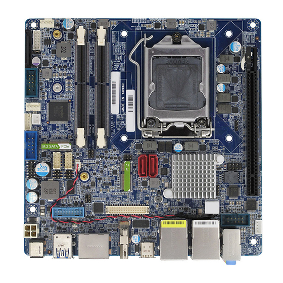
Page 14: Motherboard Layout
MX370QD User’s Manual 1.2.3 Motherboard Layout 14 MX370QD User’s Manual... -
Page 15: Layout Content List
4 x 1 wafer, pitch 2.54mm SYS_FAN1 Chassis FAN connector 4 x 1 wafer, pitch 2.54mm F_PANEL1 Intel Front Panel connector 5 x 2 header, pitch 2.54mm ATX12V1 12V-24VDC power input connectors 2 x 2 wafer MX370QD User’s Manual 15... -
Page 16: Central Processing Unit (Cpu)
The product warranty does not cover damage to the socket pins resulting from incorrect CPU installation/removal, or misplacement/loss/incorrect removal of the PnP cap. Install the CPU fan and heatsink assembly before you install motherboard to the chassis. 16 MX370QD User’s Manual... -
Page 17: Installing The Cpu
2. Press the load lever with your thumb (A), then move it to the left (B) until it is released from the retention tab. Retention tab Load lever MX370QD User’s Manual 17... - Page 18 CPU notch. CPU notch Gold triangle Alignment key 5. Pull back the load lever , then push the load lever (A) until it snaps into the retention tab. 18 MX370QD User’s Manual...
-
Page 19: Installing The Cpu Heatsink And Fan
1. Place the heatsink on top of the installed CPU, making sure that the four fasteners match the holes on the motherboard. Narrow end of the groove Fastener Motherboard hole Orient the heatsink and fan assembly such that the CPU fan cable is closest to the CPU fan connector. MX370QD User’s Manual 19... - Page 20 Do not forget to connect the fan cables to the fan connectors. Insufficient air flow inside the system may damage the motherboard components. These are not jumpers! DO NOT place jumper caps on the fan connectors. 20 MX370QD User’s Manual...
-
Page 21: Uninstalling The Cpu Heatsink And Fan
2. Rotate each fastener counterclockwise 3. Pull up two fasteners at a time in a diagonal sequence to disengage the heatsink and fan assembly from the motherboard. 4. Carefully remove the heatsink and fan assembly from the motherboard. MX370QD User’s Manual 21... -
Page 22: System Memory
(SDRAM) with a high bandwidth ("double data rate") interface. The primary advantages of DDR4 over its predecessor, DDR3, include higher module density and lower voltage requirements, coupled with higher data rate transfer speeds. DDR4 SODIMM sockets 22 MX370QD User’s Manual... -
Page 23: Installing A Sodimm
1. Press the two ejector tabs on the slot outward simultaneously, and then pull out the DIMM module. Support the SODIMM lightly with your fingers when pressing the ejector tabs. The SODIMM might get damaged when it flips out with extra force. MX370QD User’s Manual 23... -
Page 24: Expansion Card
2. Assign an IRQ to the card if needed. Refer to the tables on the next page. 3. Install the software drivers for the expansion card. 1.5.3 PCI Express x16 slot This motherboard supports one PCI Express x16 slot that complies with the PCI Express specifications. 24 MX370QD User’s Manual... -
Page 25: Connector
To install M.2 device: (1) Locate the M.2 connector on the motherboard. (2) Remove screw on the standoff. (3) Align and insert the M.2 card into the M.2 connector and lock down screw back into standoff. MX370QD User’s Manual 25... -
Page 26: Jumpers
You do not need to clear the RTC when the system hangs due to overclocking. For system failure due to overclocking, use the C.P.R. (CPU Parameter Recall) feature. Shut down and reboot the system so the BIOS can automatically reset parameter settings to default values. 26 MX370QD User’s Manual... -
Page 27: At/Atx Power Mode Select (Jpson1)
MX370QD User’s Manual 1.6.2 AT/ATX Power Mode Select (JPSON1) This jumper allows you to select ATX Mode or AT mode 1.6.3 COM POWER SETTING (JCOMPWR1~2) This jumper allows you to select COM1/COM2 to support Ring/+12V/+5V MX370QD User’s Manual 27... -
Page 28: Lvds Panel Voltage Selection (Jbklvol1)
1.6.4 LVDS panel voltage Selection (JBKLVOL1) This jumper allows you to select the voltage of LVDS panel backlight. 1.6.5 brightness control mode Selection: (JLVDS_BKL1) This jumper allows you to select the control mode of LVDS panel backlight. 28 MX370QD User’s Manual... -
Page 29: Connectors
Description No link 10Mbps connection Orange Linked Green 100Mbps connection Blinking Data Orange 1Gbps activity connection USB12 USB 3.1 These two 4-pin Universal Serial Bus (USB) Connectors ports are available for connecting USB 3.1 Gen2 devices. MX370QD User’s Manual 29... -
Page 30: Cpu And System Fan Connectors (Cpu_Fan1, Sys_Fan1)
4800rpm or a total of 1A~2.22A (26.64W max.) at +12V. Connect the fan cables to the fan connectors on the motherboard, making sure that the black wire of each cable matches the ground pin of the connector. 30 MX370QD User’s Manual... -
Page 31: System Panel (F_Panel1)
These are not jumpers! DO NOT place jumper caps on the fan connectors. 1.7.3 System Panel (F_PANEL1) This connector is for a chassis-mounted front panel. The functions are as following. MX370QD User’s Manual 31... -
Page 32: Dc-In Power Connectors (Atx12V1)
The connector is for 12V-24VDC input power supply plugs. The power supply plugs are designed to fit these connectors in only one orientation. Find the proper orientation and push down firmly until the connectors completely fit. 32 MX370QD User’s Manual... -
Page 33: Serial Port Connectors (Com1~2)
1.7.6 Serial ATA Connector (SATA1~2 ) SATA 1~2 support SATA 3.0. These connectors are for the Serial ATA signal cables for Serial ATA hard disk drives. MX370QD User’s Manual 33... -
Page 34: Usb Connectors (Usb1011)
These USB connectors comply with USB 2.0 specification that supports up to 480 Mbps connection speed. Never connect a 1394 cable to the USB connectors. Doing so will damage the motherboard! 34 MX370QD User’s Manual... -
Page 35: Usb Connector (Usb89)
1.7.9 SATA power connector (SATAPW1) 1. +3.3V 2. +3.3V 3. +3.3V 4. GND 5. GND 6. GND 7. +5V 8. +5V 9. +5V 10. GND 11. GND 12. GND 13. +12V 14. +12V 15. +12V MX370QD User’s Manual 35... -
Page 36: Lvds Panel Connector (Lvdsedp1)
1.7.10 LVDS panel connector (LVDSEDP1) 1.7.11 8 bit GPIO header (JDIO1) 1. SIO_GPIO0 2. SIO_GPIO4 3. SIO_GPIO1 4. SIO_GPIO5 5. SIO_GPIO2 6. SIO_GPIO6 7. SIO_GPIO3 8. SIO_GPIO7 9. SMB_CLK_ 10. SMB_DATA_ RESUME RESUME 11. GND 12. +5Vsb 36 MX370QD User’s Manual... -
Page 37: Front Audio Connector (Aafp1)
This connector is for a chassis-mounted front panel audio I/O module that supports either HD Audio or legacy AC ‘97 (optional) audio standard. 10. LINE2-JD 9. LINE2L 8. NC 7. SENSEB 6. MIC2-JD 5. LINE2R 4. NC 3. MIC2R 2. GND 1. MIC2L 1.7.13 Amplifier Connector (JAMP1) MX370QD User’s Manual 37... -
Page 38: Sm Bus Connector(Jsmb1)
MX370QD User’s Manual 1.7.14 SM bus connector (JSMB1) 1.7.15 LVDS panel backlight connector (JBKL1) 38 MX370QD User’s Manual... -
Page 39: Chassis Intrusion Connector(Jcase1)
MX370QD User’s Manual 1.7.16 Chassis Intrusion Connector(JCASE1) MX370QD User’s Manual 39... -
Page 40: I2C Connector (I2C1)
MX370QD User’s Manual 1.7.17 I2C connector (I2C1) 1.7.18 I2S connector(I2S1) 40 MX370QD User’s Manual... - Page 41 MX370QD User’s Manual This chapter tells how to change the system settings through the BIOS Setup menus. Detailed descriptions of the BIOS parameters are also provided. BIOS Step MX370QD User’s Manual 41...
-
Page 42: Chapter 2 - Bios Setup
The BIOS setup screens shown in this section are for reference purposes only, and may not exactly match what you see on your screen. Visit the system builder’s website to download the latest BIOS file for this motherboard 42 MX370QD User’s Manual... -
Page 43: Legend Box
<F3> to load the optimal default values. While moving around through the Setup program, note that explanations appear in the Item Specific Help window located to the right of each menu. This window displays the help text for the currently highlighted field. MX370QD User’s Manual 43... -
Page 44: Bios Menu Screen
To access the menu items, press the up/down/right/left arrow key on the keyboard until the desired item is highlighted, then press [Enter] to open the specific menu. 44 MX370QD User’s Manual... -
Page 45: Main Setup
Use this menu for basic system configurations, such as time, date etc. BIOS Information Displays the auto-detected BIOS information. System Date The date format is <Date>,<Month>,<Day>,<Year>. System Time The time format is <Hour>,<Minute>,<Second>. MX370QD User’s Manual 45... -
Page 46: Advanced Bios Setup
The Advanced BIOS Setup screen is shown below. The sub menus are described on the following pages. Take caution when changing the settings of the Advanced menu items. Incorrect field values can cause the system to malfunction. 46 MX370QD User’s Manual... -
Page 47: Cpu Configuration
Configuration options:[No change in owner EPOCHs][change to new random owner EPOCHs][Manual user defined owner EPOCHs] Intel Virtualization Technology [Enabled] When enabled, a VWM can utilize the additional hardware capabilities provided by vanderpool Technology Configuration options: [Disabled][Enabled] MX370QD User’s Manual 47... - Page 48 Enable or disable C1E. When enabled, CPU will switch to minimum speed when all cores enter C-state. Configuration options: [Enabled] [Disabled] Package C state limit [Auto] Package C state limit. Suggest to leave to factory default value. Configuration options: [C0/C1][C2][C3][C6][C7][C7S][C8][C9][C10][Cpu default][Auto] 48 MX370QD User’s Manual...
-
Page 49: Pch-Fw Configuration
Configuration options: [Enable] [Disable] ME Unlock Control [Lock] ME unlock switch function. This function will automatically recover setting from Unlock to Lock after power-on system. Configuration options: [Lock] [Unlock] 2.4.3 Trusted Computing Security device settings MX370QD User’s Manual 49... - Page 50 Enable or Disable SHA-1 PCR Bank. Configuration options: [Enable] [Disable] SHA256 PCR Bank [Disable] Enable or Disable SHA256 PCR Bank. Configuration options: [Enable] [Disable] Pending Operation [None] Schedule and operation for the Security Device. Configuration options: [None] [TPM clear] 50 MX370QD User’s Manual...
-
Page 51: Acpi Setting
Configuration options: [Suspend Disable] [S3 only(suspend to RAM )] S3 Video Repost [Disabled] Enable or disable S3 video repost Configuration options: [Disabled] [Enabled] PCIE# wake from S5 [Disabled] Enable or disable PCIE wake the system from S5. Configuration options: [Disabled] [Enabled] MX370QD User’s Manual 51... -
Page 52: Ntc6101D Super Io Configuration
WatchDog count mode [Second] WatchDog count mode Selection Configuration options: [Second] [Minute] WatchDog Timeout value Fill watchdog timeout value, 0 means disables Chassis opened warning [Disabled] Select chassis intrusion enabled to Disabled Configuration options: [Disabled] [Enabled] 52 MX370QD User’s Manual... - Page 53 Enable or Disable serial Port (COM) Configuration options: [Disabled] [Enabled] Change Setting [Auto] Select an optimal settings for super IO device Configuration options: as below COM mode Select [RS232] Configure the Com port mode Configuration options: as below MX370QD User’s Manual 53...
- Page 54 MX370QD User’s Manual 2.4.5.2 Serial Port 2 Configuration Serial Port [Enabled] Enable or Disable serial Port (COM) Configuration options: [Disabled] [Enabled] Change Settings [Auto] Select an optimal settings for super IO device Configuration options: as below 54 MX370QD User’s Manual...
-
Page 55: Ntc6106D Hw Moinitor
MX370QD User’s Manual 2.4.6 NCT6106D HW monitor Display Hardware monitor information 2.4.6.1 Smart FAN Smart FAN Function [Enabled] Smart fan function Enable/Disabled MX370QD User’s Manual 55... - Page 56 Configuration options: [Enabled] [Disabled] 2.4.6.1.1 Smart FAN mode Configuration Setting different FAN on this motherboard CHA_FAN1/CHA_FAN1 Target [Disabled] Smart FAN target temperature Configuration options: Please see below picture CHA_FAN1/CPU_FAN1 FAN Speed(%) [50%] Smart FAN minimum settings 56 MX370QD User’s Manual...
- Page 57 MX370QD User’s Manual Configuration options: Please see below picture MX370QD User’s Manual 57...
-
Page 58: S5 Rtc Wake Settings
MX370QD User’s Manual 2.4.7 S5 RTC wake settings Wake system from S5 [Disabled] Enabled or Disabled system wake on alarm event Configuration options: [Enabled] [Disabled] 58 MX370QD User’s Manual... -
Page 59: Serial Port Console Redirection
MX370QD User’s Manual 2.4.8 Serial Port Console Redirection Console Redirection [Disabled] Enabled or Disabled Console Redrection Configuration options: [Enabled] [Disabled] 2.4.9 Intel TXT information Display Intel TXT information MX370QD User’s Manual 59... - Page 60 MX370QD User’s Manual 60 MX370QD User’s Manual...
-
Page 61: Usb Configuration
This is a workaround for OSes without XHCI hand-off support. This XHCI ownership change should be claimed by XHCI drivers Configuration options: [Disabled] [Enabled] USB Mass storage Driver Support[Enabled] Enabled or Disabled USB Mass storage driver support. Configuration options: [Disabled] [Enabled] MX370QD User’s Manual 61... -
Page 62: Network Stack Configuration
Enabled IPv6 PXE boot support Configuration options: [Disabled] [Enabled] PXE boot wait time Wait time to press ESC to abort the PXE boot Media Detect Count Number of times presence of media will be checked 62 MX370QD User’s Manual... -
Page 63: Compatibility Support Module Configuration
Control the execution of UEFI and Legacy Video OpROM Configuration options: [Do not launch] [UEFI][Legacy] Other PCI devices [UEFI] Determines OpROM execution policy for devices other than Network, Storage, or Video. Configuration options: [Do not launch] [UEFI][Legacy] MX370QD User’s Manual 63... -
Page 64: Nvme Configuration
MX370QD User’s Manual 2.4.13 NVMe Configuration Display NVMe controller or Drive information 64 MX370QD User’s Manual... -
Page 65: Chipset
MX370QD User’s Manual 2.5 Chipset MX370QD User’s Manual 65... -
Page 66: System Agent (Sa) Confuguration
MX370QD User’s Manual 2.5.1 System Agent (SA) Configuration VT-d [Enabled] VT-d capability Configuration options: [Disabled] [Enabled] 2.5.1.1 Memory configuration Display memeory information 66 MX370QD User’s Manual... - Page 67 MX370QD User’s Manual Max TOLUD [Dynamic] Maximum value of TOLUD. Configuration options: As above picture 2.5.1.2 Graphic Configuration Graphic configuration settings MX370QD User’s Manual 67...
- Page 68 Select DVMT 5.0 Pre-allocated (Fixed) Graphics memory size used by the internal graphics device. Configuration options: As below picture DVMT total Gfx Mem [256M] Select DVMT 5.0 Total graphic memory size used by the internal graphic device Configuration options: [128M][256M][Max] 68 MX370QD User’s Manual...
- Page 69 MX370QD User’s Manual 2.5.1.3 LCD Control Primary IGFX Boot Display [VBIOS default] Select the video device which will be activated during POST. Configuration options: [VBIOS default][DP1][LVDS][HDMI][DP2] LVDS Control [Disable] Configuration options: [disabled][enabled] MX370QD User’s Manual 69...
- Page 70 Enable or Disable the root port Configuration options: [Disabled][Enabled][Auto] Max Link Speed [Auto] Configure PEG 0:1:0 Max Speed Configuration options: [Auto][Gen1][Gen2][Gen3] Detect Non-Compliance Device [Disabled] Detect non-compliance PCI express Device in PEG Configuration options: [Disabled][Enabled] 70 MX370QD User’s Manual...
-
Page 71: Pch-Io Configuration
Specify what state to go to when power is re-applied after a power failure. Configuration options: [Power on][Power off][Last State] GPIO Group Control [Enabled] Configure the digital GPIO pins Configuration options: [Disabled][Enabled] Amplifier GAIN(db) [15.3db] Select Amplifier GAIN value Configuration options: [15.3db][21.2db][27.2db][31.8db] MX370QD User’s Manual 71... - Page 72 ASPM Support [Disabled] Set the ASPM level: Force L0s- Force all links to L0s State; Auto- BIOS auto configure; Disabled- Disables ASPM Configuration options: [Disabled][L0s][L1][L0sL1][Auto] PCIe Speed [Auto] Select PCI Express Port speed Configuration options: [Auto][Gen1][Gen2][Gen3] 72 MX370QD User’s Manual...
- Page 73 ASPM 9 Support [Disabled] Set the ASPM level: Force L0s- Force all links to L0s State; Auto- BIOS auto configure; Disabled- Disables ASPM Configuration options: [Disabled][L0s][L1][L0sL1][Auto] PCIe Speed [Auto] Select PCI Express Port speed Configuration options: [Auto][Gen1][Gen2][Gen3] MX370QD User’s Manual 73...
- Page 74 ASPM 10 Support [Disabled] Set the ASPM level: Force L0s- Force all links to L0s State; Auto- BIOS auto configure; Disabled- Disables ASPM Configuration options: [Disabled][L0s][L1][L0sL2][Auto] PCIe Speed [Auto] Select PCI Express Port speed Configuration options: [Auto][Gen1][Gen2][Gen3] 74 MX370QD User’s Manual...
- Page 75 Configuration options: [Enabled ][Disabled] Port 2 [Enabled] Enable or Disable SATA port 2 Configuration options: [Enabled ][Disabled] Port 3 [Enabled] Enable or Disable SATA port 3 Configuration options: [Enabled ][Disabled] Configuration options: [Enabled ][Disabled] MX370QD User’s Manual 75...
- Page 76 Configuration options: [Disabled] [Enabled] USB34 Standby Power[Enabled] Enable or Disable USB standby power Configuration options: [Disabled] [Enabled] USB56 Standby Power[Enabled] Enable or Disable USB standby power Configuration options: [Disabled] [Enabled] USB89 Standby Power[Enabled] 76 MX370QD User’s Manual...
- Page 77 Selectively Enabled/Disabled the corresponding USB port from reporting a device connection to the controller. Configuration options: [Disabled] [Select Per-Pin] 2.5.2.4 HD audio Configuration HD audio[Enabled] Control Detection of the HD-Audio device. Configuration options: [Disabled] [Enabled] MX370QD User’s Manual 77...
-
Page 78: Security
MX370QD User’s Manual 2.6 Security Administrator Password Set setup Administrator Password User Password Set User Password 78 MX370QD User’s Manual... - Page 79 Secure boot mode option Configuration options: [Custom] [standard] Restore Factory keys Force system to user mode. Install factory default secure boot key database. Reset to Setup Mode Secure boot mode option Configuration options: [Custom] [standard] MX370QD User’s Manual 79...
- Page 80 MX370QD User’s Manual 2.6.1.1 Key management This sheet describe keys installation and status for secure boot. We suggest user do not change these default setting if you are not familar with secure boot setting. 80 MX370QD User’s Manual...
-
Page 81: Boot
Enable or disable Quick Boot option Configuration options: [Disabled] [Enabled] Boot mode [UEFI] Select boot mode LEGACY/UEFI Configuration options: [LEGACY] [UEFI] UEFI USB Key Drive BBS Priorities Specifies the boot device priority sequence from available UEFI USB key Drives. MX370QD User’s Manual 81... -
Page 82: Save & Exit
Discard changes and Exit Exit system setup without saving the changes. Save changes and Reset Reset the system after saving the changes. Restore Defaults Restore/Load default values for all the setup option. AMIFWUpdate Launch AMIFWupdate 82 MX370QD User’s Manual...
Need help?
Do you have a question about the MX370QD and is the answer not in the manual?
Questions and answers