
Subscribe to Our Youtube Channel
Related Manuals for Flex BMR456


Summary of Contents for Flex BMR456
- Page 1 Evaluation board for digital IBC USER GUIDE for BMR456, BMR457, BMR458 ROA 1283835...
-
Page 2: Table Of Contents
Contents Introduction ..................3 How to contact Flex Power Modules ..........3 Schematics ..................4 Component layout ................5 Power up ................... 6 Power up/down instructions ............6 4.1.1 Power Supply Connection ............... 6 4.1.2 Power-up instruction: ................ 8 4.1.3 Power-down instruction:.............. -
Page 3: Introduction
Introduction This User Guide provides a brief introduction and instruction on how to use the evaluation board ROA 1283835 together with BMR456, BMR457 and BMR458. How to contact Flex Power Modules For general questions or interest in our products, please visit our website or contact your local sales representative. -
Page 4: Schematics
Schematics Below is the top level schematics of ROA 1283835. For BMR456/457 the address is in this position 0x35 and 0x36. Figure 1: Schematics of ROA 1283835 User guide evaluation board BMR45x 2023-12-05 4 (14) -
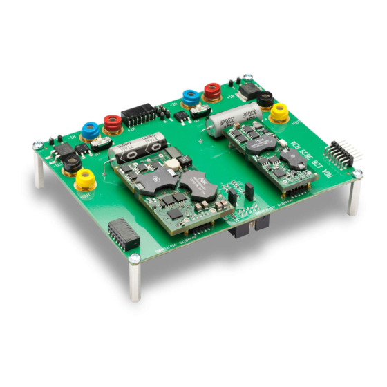
Page 5: Component Layout
Component layout In Figure 2.1 and 2.2 the component layout is shown Figure 2.1: Top side component layout of ROA 1283835 Figure 2.2: Bottom side component layout of ROA 1283835 User guide evaluation board BMR45x 2023-12-05 5 (14) -
Page 6: Power Up
Power up Power up/down instructions This section of the document describes how to connect power supply for different cases in order to avoid mistake during measurements. The jumpers that you need shall be mounted before power-up. See Section 3.2 for information about jumper positions. 4.1.1 Power Supply Connection Add the 48V DC power to one or two pairs ot the “-IN”... - Page 7 Figure 3.3a and Figure 3.4b show the connection of 2 types of USB-to-PMBus adapters Figure 3.3a: Connection of the Flex Power Modules KEP 910 17 PMBus-to-USB adapter (connector is found on the back side of the ROA 1283835 board) User guide evaluation board BMR45x...
-
Page 8: Power-Up Instruction
Figure 3.3b: Connection of the Intersil ZLUSBREF02 PMBus-to-USB adapter (connector is found on the back side of the ROA 128 3835 board 4.1.2 Power-up instruction: Mount the BMRs in the desired positions • Connect and turn On the 48V supply •... -
Page 9: Power-Down Instruction
4.1.3 Power-down instruction: Turn RC switch(es) in Off position or turn Off the 48V Supply • • Now the BMR modules can be removed/replaced Jumper positions 4.2.1 Default settings There are only two jumpers in the ROA 128 3835 board - one for the SYNC and one for CTRL. -
Page 10: Jumper Settings For Bmr 456/457
4.2.2 Jumper settings for BMR 456/457 In the figure below the jumper positions numbers for BMR456 and BMR457 are given. Using the table below, the user can make custom configurations of the board using these jumpers. Figure 4.2: Position number of the jumpers in ROA 128 3835... -
Page 11: Change Of Series Resistors For The Leds
Change of series resistors for the LEDs In order to reduce power dissipation, the series resistors for the LEDs can be changed to higher values. The resistors are located at the places shown in the figure below. Figure 5.1: Series resistors for the LEDs Change of LED series resistors R3 and R4 in position 0x2B The figure below shows where LED series resistors R3 and R4 are located Figure 5.2: Resistors R3 and R4... -
Page 12: Change Of Led Series Resistors R7 And R8 In Position 0X2D
5.1.1 Change of LED series resistors R7 and R8 in position 0x2D The figure below shows where resistors R7 and R8 located Figure 5.3: Resistors R7 and R8 User guide evaluation board BMR45x 2023-12-05 12 (14) -
Page 13: Dimensions
Dimensions The outer dimensions (in mm) of the test board are shown in the picture below. Figure 6: Mechanical information The whole testboard has the outer dimensions 140 x 110 x 39.1 mm (L x W x H). Weight of the complete test board including 2 jumpers is 180 g. User guide evaluation board BMR45x 2023-12-05 13 (14) -
Page 14: Contact Us
The contents of this document are subject to revision without notice due to continued progress in methodology, design and manufacturing. Flex shall have no liability for any error or damage of any kind resulting from the use of this document.
Need help?
Do you have a question about the BMR456 and is the answer not in the manual?
Questions and answers
How convert the BMR485 READ_IOUT (0x8c) value from the two bytes (word) hex format?