
Subscribe to Our Youtube Channel
Related Manuals for Fayat Group BOMAG BW 27 RH-4i


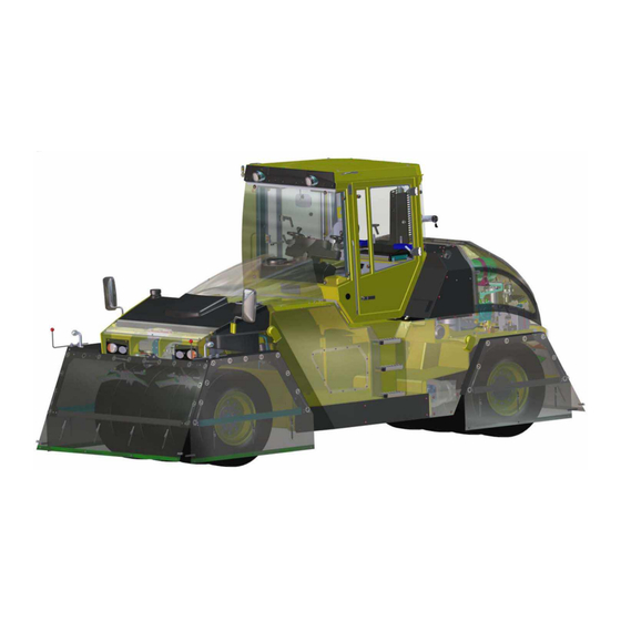
Summary of Contents for Fayat Group BOMAG BW 27 RH-4i
- Page 1 Service - Manual BW 27 RH-4i S/N 101 538 12 ..S/N 861 538 23 ../ S/N 861 538 24 ../ S/N 861 538 25 ..Rubber tire roller Catalogue number. 09/2014 008 922 89...
- Page 2 Find manuals at https://best-manuals.com...
- Page 3 Table of Contents General 1.1 Introduction 1.2 Safety regulations 1.3 General repair instructions 1.4 Tightening torques Pneumatic tires rollers 2.1 Rubber tire roller Technical data 3.1 Technical data Maintenance 4.1 General notes on maintenance 4.2 Fuels and lubricants 4.3 Table of fuels and lubricants 4.4 Running-in instructions 4.5 Maintenance table Electrics...
- Page 4 Table of Contents 9.10 Fuel pressure sensor 9.11 Charge air temperature - charge air pressure sensor 9.12 Oil pressure sensor 9.13 Sensor, water in fuel 9.14 Fuel pre-heating 9.15 Heating flange on engine 9.16 Charge control light, operating hour meter 9.17 System faults per flashing code List of EMR4 fault codes 10.1 List of EMR4 fault codes...
- Page 5 Table of Contents 12.15 Replace hydraulic oil filter 12.16 Replacing the bypass filter Brake 13.1 Overview 13.2 Brake system 13.3 Stopping the machine, operating the parking brake 13.4 Driving the machine / braking the machine 13.5 Multi-disc brake, function test 13.6 Towing in case of an engine failure Pneumatics 14.1 Overview...
- Page 6 Table of Contents Front axle 18.1 Repair overview for front axle 18.2 Dismantling the front axle 18.3 Assembling the front axle Suppliers documentation 19.1 Travel pump 19.2 Travel motor 19.3 Travel gear 19.4 Steering valve Circuit diagrams 20.1 Hydraulic diagram 538 110 00 20.2 Pneumatic diagram 538 120 00 20.3 Wiring diagram 216 BOMAG...
- Page 7 1 General 008 922 89 BOMAG Find manuals at https://best-manuals.com...
- Page 8 Introduction 1.1 Introduction This manual addresses the professionally qualified personnel or the after sales service of BOMAG, and should be of help and assistance in correct and effi- cient repair and maintenance work. This manual describes the disassembly, dismantling, assembly, installation and repair of components and assemblies.
- Page 9 Safety regulations Important notes Block the articulated joint with the articulation lock. Safety regulations Use protective clothes like hard hat, safety boots These safety regulations must be read and ap- and gloves. plied by every person involved in the repair /main- tenance of this machine.
- Page 10 Safety regulations Start the extraction fan before starting work and Operation of high-voltage systems guide with the progressing work as required. Always isolate the burner when laying it down (re- Note move possible electrode residues). The rules and statutory regulations valid in the corre- Protect cables from being damaged, use cables sponding do apply in addition to the notes given here.
- Page 11 Safety regulations Fire extinguishers charged with FOAM, CO Environment or POWDER must be available wherever fuel is It is strictly prohibited to drain off oil into the soil, stored, filled in, drained off, or where work on fuel the sewer system or into natural waters. Old oil systems is performed.
- Page 12 Safety regulations Engine air conditioning system. The development of heat may cause the refrigerant to develop toxic and high- ly corrosive breakdown products. Danger Pungent smell! The toxic substances, which are re- Do not work on the fuel system while the engine is sponsible for the pungent smell, must not be in- running.
- Page 13 Safety regulations and repair work and when taking air conditioning Dispose of used filters in accordance with applica- systems into or out of service. ble environmental regulations. When performing repair and maintenance work col- Battery lect oils and fuels in suitable containers and dispose of in compliance with applicable environmental reg- Always wear goggles and protective clothing to ulations.
- Page 14 General repair instructions General Electrics General repair instructions Before removing or disassembling parts, assem- General blies, components or hoses mark these parts for Due to the fast technical development electric and easier assembly. electronic vehicle systems become more intelligent Before assembling and installing parts, assemblies and more comprehensive day by day, and can hardly or components oil or grease all movable parts or be dispensed with in hydraulic and mechanical vehicle...
- Page 15 General repair instructions Battery Plug-in connectors on control units are only dust and water tight if the mating connector is plugged Rules for the handling of batteries on! Control units must be protected against spray water, until the mating connector is finally plugged When removing a battery always disconnect the mi- nus pole before the plus pole.
- Page 16 General repair instructions Generator Starter motor Before removing the generator you must disconnect So-called jump starting (using an additional external the ground cable from the minus pole of the battery battery) without the battery connected is dangerous. while the ignition is switched off. Do not disconnect When disconnecting the cables from the poles high in- the generator while the engine is running, because ductivities (arcs, voltage peaks) may occur and de-...
- Page 17 General repair instructions Hydraulic system Perform measurements at operating temperature of the hydraulic oil (approx. 40 ¯C). After changing a component perform a high and Caution charge pressure test, if necessary check the speed Repair work on hydraulic elements shall only per- of the exciter shaft.
- Page 18 General repair instructions Air conditioning system Damaged or leaking parts of the air conditioning must not be repaired by welding or soldering, but Chemicals/ozone layer regulation must generally be replaced. The chemicals/ozone layer regulation, which became Do not fill up refrigerant, but extract existing refrig- effective on 01.12.2006, supplements the still directly erant and refill the system.
- Page 19 General repair instructions Notes on cleanliness for Common Rail If the air conditioning system had been opened for repair work, a new drier should be installed in the re- engines frigerant circuit. Special requirements with respect to cleanliness in After completion of repair work screw locking caps the fuel system do apply for commissioning, mainte- (with seals) on all valve connections service con- nance and repair work, particularly for engines with...
- Page 20 General repair instructions Blow drying with compressed air is only permitted Do not use any previously used cleaning or testing while the fuel system is still closed. fluids for cleaning. When using steam cleaning equipment cover con- Compressed air should never be used for cleaning trol unit, cable plugs, all other electrical connections when the fuel system is open.
- Page 21 General repair instructions Fuel hoses Remove loose parts (e.g. paint scales that may have come off during assembly work) with an indus- trial vacuum cleaner or any means of extraction. Working means and tools must be cleaned before being used for work. Use only tools without dam- aged chromium coating, or tools without chromium coating.
- Page 22 General repair instructions Gaskets and mating surfaces able, you should use a plastic tube or adhesive tape to prevent the sealing lip from being damaged. Leaking sealing faces can mostly be traced back to in- correct assembly of seals and gaskets. Lubricate the outer rim (arrow 3 (Fig.
- Page 23 General repair instructions Feather keys and keyways Ball and roller bearings Caution Caution Feather keys may only be reused if they are free of Ball and roller bearings may only be reused if they damage. are free of damage and do not show any signs of wear.
- Page 24 General repair instructions Screws and nuts Check shaft and bearing housing for discolouration or other signs of movement between ball or roller Tightening torque bearing and seats. Make sure that shaft and housing are free of burrs Caution before assembling the ball or roller bearing. Tighten nuts or screws with the tightening tor- Always mark the individual parts of separable ball or ques specified in the following tables of tighten-...
- Page 25 General repair instructions Strength classes, metric screws Strength classes of metric nuts The strength classes (from 3.6 to 12.9) are specified Nuts are differentiated by three load groups. Each for all strength classes from a nominal diameter of load group has a special designation system for the 5mm.
- Page 26 General repair instructions Identification in clock system Identification of UNF-threads Fig. 10 Identification of nuts in clock system For small nuts (Fig. 10) the clock system can be used for identification. The 12 o'clock position is identified by a dot or the manufacturer's symbol.
- Page 27 General repair instructions Cotter pins Fig. 12 In places where cotter pins are used, these must be reassembled. Cotter pins must generally be renewed after disassembly. Cotter pins must be assembled as shown in the illus- tration, unless specified differently. 008 922 89 BOMAG...
- Page 28 Tightening torques The values specified in the table apply for screws: Tightening torques black oiled with surface protection A4C with surface protection DACROMET Note DACROMET is a surface protection that mainly consists of zinc and aluminium in a chromium oxide matrix. DAC- ROMETIZATION provides excellent corrosion protection for metal surfaces by applying a mineral coating with metallic-silver appearance.
- Page 29 Tightening torques Tightening torques for screws treated with anti-seizure paste OKS 240 (copper paste) Tightening torques Nm Screw dimension 10.9 12.9 M16 x 1.5 M18 x 1.5 M20 x 1.5 M22 x 1.5 M24 x 2 1036 1184 1520 M27 X 2 1263 1536 1136...
- Page 30 Tightening torques The values specified in the table apply for screws: black oiled with surface protection A4C with surface protection DACROMET Note The difference between Withworth and UNF/UNC threads is the fact that UNF and UNC threads have 60° flanks, as the metric ISO-thread, whereas Withworth has a flank of only 55°.
- Page 31 Tightening torques Tightening torques for screws with UNF thread, UNF Unified National Fine Thread Series, American Unified Fine Thread Tightening torques Nm Screw dimension 10.9 12.9 1“ - 12 1300 1600 1 1/8“ - 12 1350 1900 2300 1 1/4“ - 12 1900 2700 3200...
- Page 32 Tightening torques BOMAG 008 922 89...
- Page 33 2 Pneumatic tires rollers 008 922 89 BOMAG...
- Page 34 Rubber tire roller Rubber tire roller Flexible and economical compaction Drive concept: efficient and reliable BOMAG pneumatic tired rollers BW 24 RH / BW 27 RH combine conventional compaction technology with a state-of-the-art hydrostatic drive. For this purpose the rear axle is replaced by two hydraulic motors. This is effi- cient and optimizes operating and maintenance costs.
- Page 35 Rubber tire roller high weight of the rollers (up to 27 t) generates vertical pressure combined with horizontal forces to all directions under the wheels. Fig. 13 Flexible weight adaptation The BOMAG rollers BW 24 RH and BW 27 RH can be flexibly adapted to the corresponding compaction task. Various ballasting modes can be used for this purpose.
- Page 36 Rubber tire roller Even weight distribution to each individual wheel. Tipping resistant design with level compensation Fig. 15 BOMAG 008 922 89...
- Page 37 3 Technical data 008 922 89 BOMAG...
- Page 38 Technical data Technical data Fig. 16 BW 27 RH-4i Dimensions in 3700 2098 2840 3090 4940 2042 Dimensions in 145.7 82.6 111.8 121.7 11.8 194.5 80.4 inch Weights Operating weight (CECE) with ROPS-cabin 8800 kg 19400 lbs Max. operating weight 27000 kg 59525 lbs Max.
- Page 39 Technical data Steering Type of steering 2 point pivot steering 2 point pivot steering Steering operation hydrostatic hydrostatic Steering angle +/- 30 ° +/- 30 ° Oscillation of front wheels 4° 4° Level compensation 100 mm 3.9 in Inner track radius 5320 mm 209.4 in Tires...
- Page 40 Technical data Displacement /rev Max. steering pressure 175 ± 10 Travel gear Manufacturer Bonfiglioli Type 606Y Quantity Reduction ratio Steering valve Type OSPC 250 LS System Rotary valve Front axle Toe-in 2±1 Tables The following tables show the dependence on area pressure and area for a given load and the adjusted air pressure for tire size 11.00-20 18PR Compactor Smooth.
- Page 41 This as a preview PDF file from best-manuals.com Download full PDF manual at best-manuals.com...
Need help?
Do you have a question about the BOMAG BW 27 RH-4i and is the answer not in the manual?
Questions and answers