Advertisement
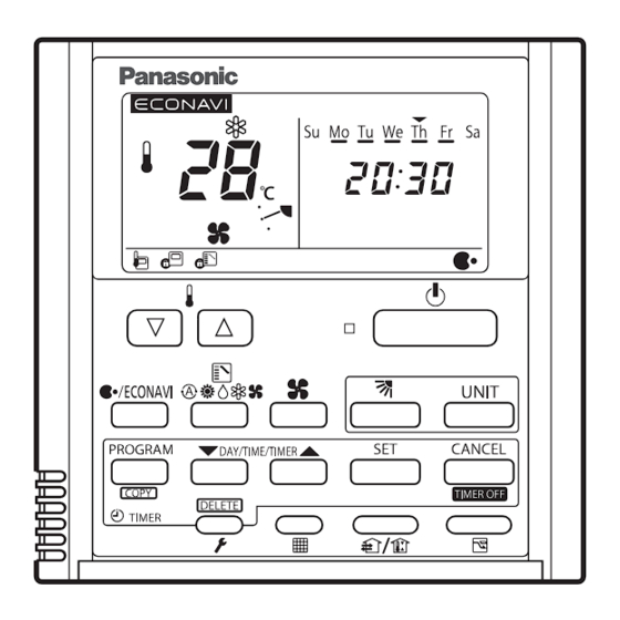
Timer Remote Controller
Installation Instruction
°
https://eu.datanavi.ac.smartcloud.panasonic.com/documents/index.htm?model=CZ-RTC4A
SAFETY PRECAUTIONS
•
Read the following "SAFETY PRECAUTIONS" carefully before installation.
•
Electrical work must be installed by a licensed electrician.
•
The caution items stated here must be followed because these important contents are related to safety.
The meaning of each indication used is as below.
Incorrect installation due to ignoring of the instruction will cause harm or damage, and the seriousness is classifi ed
by the following indications.
WARNING
This indication shows the possibility of causing death or serious injury.
CAUTION
This indication shows the possibility of causing injury or damage to properties.
The items to be followed are classifi ed by the symbols:
Symbol with white background denotes item that is PROHIBITED from doing.
Symbol with dark background denotes item that must be carried out.
•
Carry out test running to confi rm that no abnormality occurs after the installation. Then, explain to user the
operation, care and maintenance as stated in instructions. Please remind the customer to keep the operating
instructions and installation instruction for future reference.
WARNING
Do not modify the length of the remote controller cable. Otherwise, it will cause fi re or electrical shock.
Be sure to turn off the main power before installing and connecting the remote controller. Otherwise, it will
cause the electrical shock.
Engage authorized dealer or specialist for installation. If installation done by the user is defective, it will cause
electrical shock or fi re.
Install according to this installation instructions strictly. If installation is defective, it will cause electrical shock
or fi re.
Use the attached accessories parts and specifi ed parts for installation. Otherwise, it will cause the set to fall,
fi re or electrical shock.
For electrical work, follow the local national wiring standard, regulation and this installation instruction.
Otherwise, it will cause the electrical shock or fi re.
Wire routing must be properly arranged so that control board cover is fi xed properly. If control board cover is
not fi xed perfectly, it will cause fi re or electrical shock.
If passing the remote controller cable through a wall, be sure to install a water trap above the cable.
Otherwise, it will cause the electrical shock.
CAUTION
Do not touch the sharp aluminium fi n of air conditioner unit during wired remote controller installation,
sharp parts may cause injury.
Install in a fl at surface to avoid warping of remote controller, else damage to the LCD case or operation
problems may result.
Avoid installing the remote controller cable near refrigerant pipes or drain pipes, else will cause electrical
shock or fi re.
Install the remote controller cable at least 5cm away from electric wires of other appliances to avoid miss
operation (electromagnetic noise).
Be sure to use only the accessory screws to avoid damage of remote controller PCB.
Supplied Accessories
Model No. : CZ-RTC4A
(2)
Screw M3.8 × 16
*Remote control wiring is not supplied. (fi eld supplied item)
Dimensions
167
1. Installation Precautions
Installation location
•
Install at the height of 1 to 1.5 m from the fl oor (Location where average room temperature can be detected).
•
Install vertically against the fl oor.
•
When installing more than 1 remote controller next to each other, keep distance of 5 mm on the right and left and
50 mm on top and bottom.
•
Avoid the following locations for installation.
• By the window, etc. exposed to direct sunlight or direct air
• In the shadow or backside of objects deviated from the room airfl ow.
• Location where condensation occurs (The remote controller is not moisture proof or drip proof.)
• Location near heat source
• Uneven surface
•
Keep distance of 1 m or more from the TV, radio and PC. (Cause of fuzzy images or noise)
CAUTION
•
Do not use the remote controller at the following locations.
• Location where condensation occurs
• Location where fl ammable gases, etc. may leak
• Location where corrosive gases, etc. may leak
• Location with lots of water or oil droplets (including machine oil)
• Location where voltage fl uctuation frequently occurs
• Location where there is a machine producing electromagnetic radiation
• Location where droplets of organic solvents spread
• Location where acidic or alkaline solutions or special sprays are frequently used
•
Do not operate with wet hands.
•
Do not wash with water.
(1)
Quick Reference
23
23
120
120
24.75
20
5 mm or more
50 mm or
more
1 to 1.5 m
Floor
Remote control wiring
Wiring diagram
Indoor unit
R1
R2
RC wiring (fi eld supply)
• No polarity
Terminals for RC wiring
Type of wiring
Use cables of 0.5 to 1.25 mm
2
.
Total wire length: 500 m or less
(The wire length between indoor units should be 200 m or less.)
6-4.7x10.7
Number of connectable units
Remote controller: Max. 2
Indoor unit: Max. 8
Attention
•
Use the fi eld supplied RC wiring with at least 1 mm in thickness of insulation part including the sheath.
83.5
Regulations on wire diameters differ from locally to locally. For fi eld wiring rules, please refer to your LOCAL
ELECTRICAL CODES before beginning. You must ensure that installation complies with relevant rules and
regulations.
•
Be careful not to connect cables to other terminals of indoor units (e.g. power source wiring terminal). Malfunction
may occur.
•
Do not bundle together with the power source wiring or store in the same metal tube.
Operation error may occur.
•
If noise is induced to the unit power supply, attach a noise fi lter.
(mm)
*Wiring as shown below is prohibited.
Installation example
RC
RC
1 2
1 2
RC wiring
R1 R2
Indoor unit
When setting both the main and sub remote controllers
After installation, set one remote controller to [Main] and the other to [Sub] for [Main/sub]. Refer to section "Setting"
(P.2) for details.
Installation example
Using 1 indoor unit
Using more than 1 indoor unit
RC (main)
RC (sub)
RC (main)
1 2
1 2
1 2
Terminals for
RC wiring
RC wiring
R1 R2
R1 R2
Indoor unit
Indoor unit
*Remote controllers can be connected to any indoor unit for operation.
RC
1
2
R1 R2
R1 R2
1 2
Indoor unit
Indoor unit
RC
RC (sub)
1 2
RC wiring
R1 R2
R1 R2
R1 R2
Indoor unit
Indoor unit
Indoor unit
ENGLISH
ACXF60-54230-AA
1/2
PRINTED IN CHINA
Advertisement
Table of Contents

Related Manuals for Panasonic CZ-RTC4A


Summary of Contents for Panasonic CZ-RTC4A
- Page 1 Remote control wiring Supplied Accessories Model No. : CZ-RTC4A Wiring diagram Indoor unit Timer Remote Controller Installation Instruction RC wiring (fi eld supply) • No polarity Screw M3.8 × 16 Quick Reference Terminals for RC wiring *Remote control wiring is not supplied. (fi eld supplied item) ...
- Page 2 • Align the claws of the top case and then align the claws of the bottom case. 3. Setting/Test Operation/Specifi cations 4. List of Compatible Indoor Unit with CZ-RTC4A Top case Bottom case Setting Indoor unit which connects to CZ-RTC4 can be connected to CZ-RTC4A (Back side) (Back side) Clock S-22MU2E5BN S-160MF3E5AN S-22MZ1H4A S-56MD1E5...
Need help?
Do you have a question about the CZ-RTC4A and is the answer not in the manual?
Questions and answers