Advertisement
Table of Contents
USE AND MAINTENANCE
INSTALLATION INSTRUCTIONS
PARTS CATALOGUE
DATE ____________ APPROVED ____________
VIMEC reserves the right to make modifications and changes to its products at any moment in response to developments in technology.
S11 MODEL
MANUAL CODE
7512020/a
01/09/2015
Original instructions
Vimec s.r.l
Via Parri, 7 - 42045 Luzzara - Reggio Emilia - Italy
Tel. + 39 0522 970 666 - Fax. + 39 0522 970919
www.vimec.biz
Page 03 - 14
Page 15 - 26
Page 27 - 69
Advertisement
Table of Contents

Related Manuals for vimec S11

Summary of Contents for vimec S11
- Page 1 INSTALLATION INSTRUCTIONS Page 15 - 26 PARTS CATALOGUE Page 27 - 69 MANUAL CODE 7512020/a DATE ____________ APPROVED ____________ 01/09/2015 VIMEC reserves the right to make modifications and changes to its products at any moment in response to developments in technology.
-
Page 2: Ec Declaration Of Conformity
Name: Marco Marchetti Address: Via Parri n.7 , 42045 Luzzara (R.E.) ITALIA - Tel. +39/0522/970666) states on his own responsibility that the vertical lifting platform type: S11 – Serial number: complies with the following Directives: - Directive 2004/108/EEC “Electromagnetic Compatibility”... -
Page 3: Use And Maintenance
7511020 USE AND MAINTENANCE GENERAL CONTENTS 1. Unit and manufacturer identification Page 2. After-Sales Service Page 3. Description of unit Page 4. Intended and improper uses Page 5. Technical data Page 6. Preparing the lift for operation Page 7. Correct use of the platform lift Page 8. -
Page 4: After Sales Service
7511020 7512020 1) UNIT AND MANUFACTURER IDENTIFICATION I - 42045 LUZZARA (RE) Via Parri N° 7 - Tel. 0522 / 970666 TYPE SERIAL No. (N°) - - - - YEAR - - - - LOAD (kg) POWER (V / A / Hz) 220 / 6 / 50 LOAD 400 kg SERIAL No. -
Page 5: Description Of The Unit
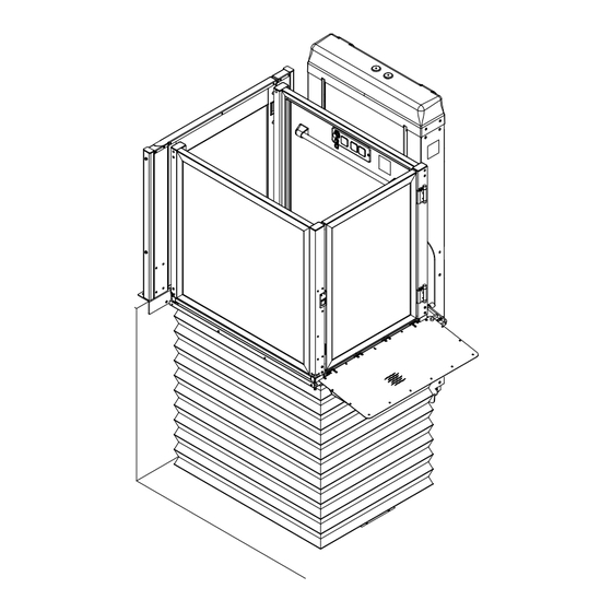
3) DESCRIPTION OF THE UNIT 3.1) General Description - Fig. 1 FIG.1 The S11 lift is a platform lift designed to trans¬port disabled persons with or without an attendant. This machine can work both in open and closed shaft. The shaft, if required, is an enclosed metallic (Fig. 2/a) or masonry structure with floor doors (Fig. - Page 6 7511020 7512020 Lifting system - Fig. 3 FIG.3 The lifting system comprises: - Motor (Fig. 3/a) - Worm (Fig. 3/b) - Nut screw (Fig. 3/c) - Safety nut screw (Fig. 3/d) - Control system (Fig. 3/e) - Brake (if present) (Fig. 3/f) A call/send floor control containing the following devices is provided near each floor door (if present) (Fig.
- Page 7 - Nameplate stating payload and those permitted to use the lift (Fig. 8/c). The lift system must be installed by skilled FIG.8 staff authorised by VIMEC. 3.5) Reference Directives The lift complies with the following directives: - 2004/108/EEC “Electromagnetic Compatibility”...
-
Page 8: Technical Data
4) INTENDED AND IMPROPER USES 4.1) Intended Uses The S11 platform lift is a lift system designed for one disabled person, standing or in a wheelchair + attendant (if any), who must be trained in the lift’s operation. When using the lift, compliance with the instructions provided on the signs fitted to it is compulsory. - Page 9 7511020 7512020 7.3) Ensure that the load is stable. 6) PREPARING THE LIFT FOR OPERATION 7.4) Check that there are no foreign bodies underneath 6.1) Electrical panel and installation the platform. The customer is required to make all necessary mo- 7.5) Check that the platform is not working in a difications required to the stairwell (before delivery), hazard¬ous environment (dust, salt, flammable or...
- Page 10 7511020 7512020 7.7) Use FIG.10 While the platform lift is in motion the wheel- chair’s brakes must be engaged and if it is electric it must be switched off. Floor controls: The controls must be kept pressed throughout the transit and cut out the lift if released. The floor locks and the on-board control panel are only operational if the key has been inserted.
- Page 11 7511020 7512020 FIG.12 - Only use the emergency gate opening keys (Fig. 13/a) STANDARD when necessary. - The platform lift may only be used by a person stand¬ing or in a wheelchair, with or without attendant. All other uses are forbidden. 7.9) Recovering the passenger in an emergency Skill level required OC: Trained operator with spe¬cific skill.
- Page 12 7511020 7512020 WARNING: The gate must be unlocked only FIG.14 when the platform reaches the destina¬tion floor. Close the gate and call the after-sales service. Instructions to unlock the door from inside the pit for hinged doors (for the maintenance operator) When the machine is in the pit: - Remove the cover.
-
Page 13: Safety Systems
Use of the platform is only enabled with the correct lock USE the lift!! status; the unit cannot be used if the gates are open or Call in an authorised VIMEC technician at once. the locks have been tampered with. g) Movement cut-out in the event of obstacles... - Page 14 7511020 7512020 Photocell kit for 1 side guard Photocell kit for 2 sides guard Photocell kit for 4 sides guard...
-
Page 15: Maintenance
7512020 9) MAINTENANCE Although the lift has of course undergone rigorous testing, VIMEC advices you to have it inspected regularly by technicians. In order to ensure that it provides the best service in complete safety, our specialist engineers, who will carry out all the operations described below must inspect it regularly 9.1) Parts requiring regular inspection... - Page 16 7511020 7512020 FIG.16 9.2) Check and replacement of nuts The two upper and lower nuts coupled to the lead screw and placed in the column, during the machine operation wear proportionally to the number of cycles and to the load applied to the platform (people weight). Therefore, it is necessary to replace the nuts after a certain number of cycles.
-
Page 17: Electrical Wiring Diagrams
The platform does not move in either direction Emergency STOP pressed Turn the button clockwise through 45° Overload cut-out tripped Press the reset button Differential circuit-breaker Call a VIMEC authorised tripped technician Lift gate Close the gate properly. Gates and locks Close the gates properly... -
Page 18: Installation Instructions
7511020 7512020 INSTALLATION INSTRUCTIONS GENERAL CONTENTS 1) Lift supply package Page 19 2) Place of installation Page 19 3) Transport Page 19 4) Installation instructions Page 19 5) Final testing Page 31 6) Operating checks and adjustments Page 31... -
Page 19: Place Of Installation
7511020 7512020 1. LIFT SUPPLY PACKAGE - Utilizzare un apparecchio di sollevamento e fasce - Complete platform d’imbragatura per accostare la colonna al muro in - Preassembled column or column disassembled into posizione verticale. 2 parts - Upper floor gate complete with controls - Panelling - Remote call column (OPT) FIG.1... - Page 20 7511020 7512020 WARNING: FIG.5 Use a spirit level to check that it is vertical (Fig. 2/a), and also check that the floors are perpendicular compared to the wall and to the base plinth (Fig. 3). - Use plugs to fix the column to the wall by the base connection (Fig.
- Page 21 7511020 7512020 4.1/B Mounting the column in metal scaffold FIG.9 Using the screws provided (Fig. 10/b), secure the column to the crossbeams of the scaffold in the points indicated in Fig.9/a and Fig.8/a. Level the base adjusting the screws (Fig. 7/a) if ne- cessary.
- Page 22 7511020 7512020 FIG.12 4.2 Wall mounting of the column for machine disas- sembled into 2 parts Supply package: - Upper column (Fig. 11). - Lower column (Fig. 12). - Supporting pipes for front casings. - Cable through - Set of casings (side, upper, rear and front) Proceed with joining the lower column to the upper one.
- Page 23 7511020 7512020 - Then proceed with coupling the two worm screws with FIG.16 Ø 4 stop pin (Fig. 14). - Connect the two separated pipes using the special joint plate provided (Fig. 17/a) and the screws ISO 4017 M6x20 (Fig. 17/b). - After, proceed with assembling the front casing sup- porting pipes and the cable through (Fig.
- Page 24 7511020 7512020 FIG.19 4.3 Mounting the mechanical stop The mechanical stop safety device is shown in Fig. 18. When this device is included in the supply, during in- stallation it has to be fixed to the base using the screw (Fig.
- Page 25 7511020 7512020 Make sure that in this position the microswitch (marked FIG.21 in Fig. 21/a) triggers. The motor lifting the platform cannot be powered. The stop in horizontal position is shown in Fig. 22. In this position, the microswitch is deactivated and in this case, the machine works normally.
- Page 26 7511020 7512020 4.4 Mounting the platform FIG.23 Without shaft - Raise the platform and position it so that the slotted plates coincide with those on the trolley (Fig. 23/a). NOTE: Before fixing the platform, close the bellows (if present) with straps (Fig. 24/a). This operation makes it easier to mount the platform with bellows, without creating impediments.
- Page 27 7511020 7512020 FIG.27 4.6 Mounting the lift gate - After fixing the on board guards on the column side and on the column opposite side, secure the lift gate by screwing the hinges to the upright (Fig. 26). 4.7 Mounting the 90° landing guard - After fixing the tubular sections for 90°...
- Page 28 7511020 7512020 FIG.30 4.10 Mounting the 1st floor gate - Install the top floor gate, complying with the stated measurements, and fix it to the ground and to the wall using the expansion plugs (Fig. 30). 4.11 Electrical wiring - Connect the wiring to the push-button board. - Connect the electrical wiring of the bottom safe edge (if present).
- Page 29 7511020 7512020 FIG.35 4.12 Mounting frontal casings Move the platform to the floor using the on-board controls. Insert the long casing (Fig. 34/a), previously dismantled, between the platform and column, then fix it to the feet screwed to the pipes. Then fix the second casing (short) (Fig.
- Page 30 7511020 4.15 Mounting the handlebar (if present) Drill holes in the wall as indicated in Fig. 38, then fix the handlebar using the screws and the counter-plate provided (Fig. 38/b). 4.16 Mounting the photocells Fix the reading electronic card to the support (Fig. 39/a), then assemble the whole unit on side shown in the figure (Fig.
-
Page 31: Final Testing
7511020 5) FINAL TESTING Skilled staff authorised by VIMEC must test the lift system. Run the lift up and down a few times, checking that: - There is no interference between the platform and the shaft. - There are no unusual vibrations or strange noises. - Page 32 7511020 PARTS CATALOGUE USO E MANUTENZIONE CONTENTS OF THE CATALOGUE Column Page 33 Casing Page 35 Nuts Page 37 Rails and accessories Page 39 On-board control panel Page 41 Floor control panel Page 43 Lock Page 45 Bellows Page 47 Platform Page 49 Three-phase electrical system...
- Page 33 COLUMN 7511020...
- Page 35 CASING 7511020...
- Page 37 otes Unit.Wg NUTS 7511020...
- Page 39 7511020 RAILS AND ACCESSORIES...
- Page 45 LOCK 7511020...
- Page 47 BELLOWS 7511020...
- Page 49 PLATFORM 7511020...
- Page 51 THREE-PHASE 7511020 ELECTRICAL SYSTEM...
- Page 55 COLUMN OPPOSITE GUARD 7511020...
- Page 57 RAIL SIDE ON-BOARD 7511020 GUARDS...
- Page 59 STANDARD GATE 7511020...
- Page 61 7511020 MOTOR-OPERATED GATE...
- Page 63 LIFT GATE 7511020...
- Page 65 REMOTE CALL COLUMN 7511020...
- Page 67 HANDLEBAR 7511020...
- Page 69 GREASER 7511020...
- Page 71 PHOTOCELLS 7511020...
Need help?
Do you have a question about the S11 and is the answer not in the manual?
Questions and answers