Table of Contents
Advertisement
Quick Links
VIKING-9XXB Series
th
12.1"/19"/24" Intel 8
Core i3/i5 Marine Panel PC
User Manual
Release Date
Revision
Jan 2024
V1.0
®2024 Aplex Technology, Inc. All Rights Reserved. Published in Taiwan
Aplex Technology, Inc.
15F-1, No.186, Jian Yi Road, Zhonghe District, New Taipei City 235,Taiwan
Tel: 886-2-82262881 Fax: 886-2-82262883 E-mail:
aplex@aplex.com
URL:
www.aplex.com.tw
Advertisement
Table of Contents

Related Manuals for Aplex VIKING-9 B Series


Summary of Contents for Aplex VIKING-9 B Series
- Page 1 Core i3/i5 Marine Panel PC User Manual Release Date Revision Jan 2024 V1.0 ®2024 Aplex Technology, Inc. All Rights Reserved. Published in Taiwan Aplex Technology, Inc. 15F-1, No.186, Jian Yi Road, Zhonghe District, New Taipei City 235,Taiwan Tel: 886-2-82262881 Fax: 886-2-82262883 E-mail: aplex@aplex.com URL:...
- Page 2 Revision History Reversion Date Description 2024/01/05 Official Version VIKING-9XXB Series User Manual...
- Page 3 Warning!________________________ This equipment generates, uses and can radiate radio frequency energy and if not installed and used in accordance with the instructions manual, it may cause interference to radio communications. It has been tested and found to comply with the limits for a Class A computing device pursuant to FCC Rules, which are designed to provide reasonable protection against such interference when operated in a commercial environment.
-
Page 4: Packing List
Packing List Accessories (as ticked) included in this package are: □ Adaptor □ Driver & manual CD disc □ Other.___________________(please specify) VIKING-9XXB Series User Manual... -
Page 5: Safety Precautions
Safety Precautions Follow the messages below to prevent your systems from damage: ◆ Avoid your system from static electricity on all occasions. ◆ Prevent electric shock. Don‘t touch any components of this card when the card is power-on. Always disconnect power when the system is not in use. -
Page 6: Table Of Contents
Table of Contents Revision History…………………………………………………………………………………………………….1 Warning!/Caution……………………..........…………………………….…2 Packing List…………………………………….……………………………………………………………………..3 Safety Precautions…………………………………………………………………….…..……………………..4 Chapter 1 Getting Started 1.1 Features………………………..………………………...…………………………..8 1.2 Specifications…………………...………………………………………………….8 1.3 Dimensions………………………..…………………………………………….12 1.4 Brief Description of VIKING-9XXB Series………..…….……….……15 1.5 Yoke Mounting and VESA Mounting……………………………………16 Chapter 2 Hardware 2.1 Motherboard Introduction……………………...……………..………..17 2.2 Specifications…………………………..…………………………………………17 2.3 Jumpers and Connectors Location……………………………………...20 2.4 Jumpers Setting and Connectors…………………………………..……21 Chapter 3... - Page 7 Figures Figure 1.1: Dimensions of VIKING-912BP(H)…………….…..……………………10 Figure 1.2: Dimensions of VIKING-919BP(H)……….….……….…………………11 Figure 1.3: Dimensions of VIKING-924BP(H)…………...….…..…………………12 Figure 1.4: Front View of VIKING-912BP(H)…………….……….…………………14 Figure 1.5: Rear View of VIKING-912BP(H)………………..……………………….14 Figure 1.6: Front View of VIKING-919BP(H)…………..…….……………………..15 Figure 1.7: Rear View of VIKING-919BP(H)…………..………………….……….15 Figure 1.8: Front View of VIKING-924BP(H)…..…….….……..…………….….16 Figure 1.9: Rear View of VIKING-924BP(H)………………….…………..………..16 Figure 1.10: VESA Mounting of VIKING-9XXB Series......16...
-
Page 8: Getting Started
Chapter 1 Getting Started 1.1 Features ⚫ Intel® Core 8 Gen i3/i5 Processor ⚫ 12.1”/19”/24” TFT LCD ⚫ Aluminum Enclosure (with Anti-Corrosion Coating) ⚫ True Flat Bezel Design ⚫ IP66 Front Panel ⚫ 1 x 260pin SO-DIMM, up to 32GB DDR4 2400MHz ⚫... - Page 9 1 x ESD Ground Storage Space Storage Default 1 x M.2 M-Key support 2242 SSD (2280 for option, can’t use TB-528 at the same time) 1 x 2.5” HDD space (Option) Expansion Expansion Slot 1 x Full-size mPCIe slot onboard 1 x TB-528 expansion connector (CN3, for 19”/24”) (option TB-528C2I for 2 x RS-422/485 isolation) Display –...
- Page 10 Construction Black/Aluminum bezel and Aluminum housing (Anti-corrosion coating) Mounting Panel Mount/VESA mount IP Rating IP66/IP69K Dimension (mm) 307 x 246 x 73.5 439 x 396 x 76.3 609 x 400 x 76.3 Net Weight 4.07 Kg 7.15 Kg 8.88 Kg Environmental Operating 0~50°C (-20~60°C for option)
-
Page 11: Dimensions
1.3 Dimensions Figure 1.1: Dimensions of VIKING-912BP(H) VIKING-9XXB Series User Manual... -
Page 12: Figure 1.2: Dimensions Of Viking-919Bp(H)
Figure 1.2: Dimensions of VIKING-919BP(H) VIKING-9XXB Series User Manual... -
Page 13: Figure 1.3: Dimensions Of Viking-924Bp(H)
Figure 1.3: Dimensions of VIKING-924BP(H) VIKING-9XXB Series User Manual... -
Page 14: Brief Description Of Viking-9Xxb Series
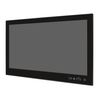
1.4 Brief Description of VIKING-9XXB Series There are 12.1”, 19” and 24” new generation adopt Black/Aluminum bezel and Aluminum housing panel PC in VIKING-9XXB series, which comes with 100% dust and waterproof guarantee, and the all-in-one fanless design. It is powered by 8 Gen. - Page 15 Figure 1.4: Front View VIKING-912B Figure 1.5: Rear View of VIKING-912B VIKING-9XXB Series User Manual...
- Page 16 Figure 1.6: Front View VIKING-919B Figure 1.7: Rear View of VIKING-919B VIKING-9XXB Series User Manual...
- Page 17 Figure 1.8: Front View VIKING-924B Figure 1.9: Rear View of VIKING-924B VIKING-9XXB Series User Manual...
- Page 18 1.5 Panel Mount and VESA Mount The VIKING-9XXB Series model can be Panel mounted and VESA mounted as shown in Picture below. Figure 1.9: Panel mount of VIKING-9XXB Series Figure 1.10: VESA mount of VIKING-9XXB Series VIKING-9XXB Series User Manual...
-
Page 19: Chapter 2 Hardware
Chapter 2 Hardware 2.1 Motherboard Introduction SBC-7124 is a 4” industrial motherboard developed on the basis of Intel Whiskey Lake-U Processor, which provides abundant peripheral interfaces to meet the needs of different customers. Also, it features dual GbE ports, 6xCOM ports and one M.2 M-Key configuration, one DP Port and one LVDS interface. - Page 20 1 x USB 2.0 Pin header for CN1 (USB7) 1 x USB 2.0 Pin header for CN2 (USB8) 1 x USB 2.0 for M-PCIE1 (USB9) 1 x USB 2.0 for PM6000 (USB10) 1 x PH3y.50mm, 2*5Pin Connectors for external (COM1_1) 1 x RS232 port, Pin1 w/5V/12~14VRTS select (COM1_1-1) Serial 1 x RS232/RS422/RS485 port (COM1_1-2)
-
Page 21: Figure 2.1: Motherboard Dimensions
1 x DP Port 1 x Audio Jack (Line out) Infineon’s Trusted Platform Module (TPM 2.0) *Note: Only support Windows 10 IOT* Operating: -20℃ to 70℃ Temperature Storage: -40℃ to 85℃ Humidity 10% - 90% relatively, non-condensing, operating Power 24V/1.6A (Intel i3-8145UE Processor with 16GB DDR4/HDD) Consumption 24V/2.0A (Intel i5-8365UE Processor with 16GB DDR4/HDD) EMI/EMS... -
Page 22: Jumpers And Connectors Location
2.3 Jumpers and Connectors Location Figure 2.2: Jumpers and Connectors Location- Board Top Figure 2.3: Jumpers and Connectors Location- Board Bottom VIKING-9XXB Series User Manual... -
Page 23: Jumpers Setting And Connectors
2.4 Jumpers Setting and Connectors 1. CPU1: 2. H1/H2/H3/H4 (option): CPU1 Heat Sink Screw holes, four screw holes for Intel Whiskey Lake-UE Processors. Heat Sink assembles. 3. FAN1: (2.54mm Pitch 1x4 Pin Header), FAN connector, cooling fans can be connected directly for use. - Page 24 4. DDR4_1: (SO-DIMM 260Pin slot), DDR4 memory socket, the slot is located at the socket of the board and supports 260Pin 1.2V DDR4 2400MHz FSB SO-DIMM memory module up to 32GB. Model DDR4 Memory Types (FSB) SBC-7124-I3-8145UE 2400MHz SBC-7124-I5-8365UE 2400MHz 5.
- Page 25 c) Power on the system again. d) When entering the POST screen, press the <DEL> key to enter CMOS Setup Utility to load optimal defaults. e) After the above operations, save changes and exit BIOS Setup. 7. BAT2: (2.0mm Pitch 1x10 Wafer Pin Header), Smart battery Interface Pin# Signal Name Pin1...
- Page 26 BAT2 (option) BAT2 DC_IN1 + BAT2 (option) DC_IN1 9. BT1: Power on/off button, it is used to connect power switch button. The two pins are disconnected uncer normal condition. You may short them temporarily to realize system startup & shutdown or awaken the system from sleep state. 10.
- Page 27 SBC-7124-I5-8365UE 800*480 (option) SBC-7124-I7-8665UE 800*600 (option) 1024*768 (option) 1920*1080 (option) …… 13. INVT1: (2.0mm Pitch 1x6 wafer Pin Header), Backlight control connector for LVDS. Pin# Signal Name +DC12V_LVDS +DC12V_LVDS Ground Ground BKLT_EN_OUT BKLT_PWM_OUT 14. CN1: (1.25mm Pitch 2x20 Connectorm DF13-40P), for 18/24-bit LVDS output connector, fully supported by Parad PS8625 (DP to LVDS), the interface features dual channel 24-bit output.
- Page 28 LA_D2_P LA_D2_N LA_D3_P LA_D3_N LA_CLKP LA_CLKN LB_D0_P LB_D0_N LB_D1_P LB_D1_N LB_D2_P LB_D2_N LB_D3_P LB_D3_N LB_CLKP LB_CLKN USB7 Ground Ground (option) USB7_P USB7_N 5V_S5_USB 5V_S5 Power LED PWR_LED+ Ground 15. DP1: (DP Connector), Display Port Interface connector. 16. SW1 (Pin5): SW1-5 (Switch), Touch jumper setting. SW1(Switch) Touch (TCH1) SW1-5 OFF (Default)
- Page 29 18. JP2: (2.0mm Pitch 2x3 Pin Header), COM1 jumper setting, pin1~6 is used to select signal out of pin 1 of COM1 port. JP1 Pin# Function Close 1-2 COM1 Pin1 RTS (Default) Close 3-4 COM1 Pin1: DC+5V (option) Close 5-6 COM1 Pin1: DC+12V~14V (option) 19.
- Page 30 Caution: Please Pay attention to pin1 pin definition. The power output might damage your device if is connected to the RTS port. 20. SATA_P1: (2.5mm Pitch 1x2 box Pin Header), one onboard 5V output connector is reserved to provide power for SATA devices. Pin# Signal Name 5V_S0 (+DC5V output)
- Page 31 26. SIM1: (NANO-SIM Socket), Support nano SIM Card devices. 27. F_AUDIO1: (2.0mm Pitch 2x6 Pin Header), front audio, an onboard Realtek ALC888C-VD2 codec is used to provide high-quality audio I/O ports. Line Out can be connected to a headphone or amplifier. Line in is used for the connection of external audio source via a Line in cable.
- Page 32 Each USB Type A Receptacle (2 Ports) Current limited value is 2.0A. If the external USB device current exceeds 1.5A, please separate connectors into different Receptacle. 30. USB3_2: USB3-3/USB3-4: (Double stack USB type A), rear USB connector, provides up to two USB3.2 Gen1 ports, High-speed USB 2.0 allows data transfer up to 480 Mb/s, USB 3.2 Gen1 allows data transfer up to 5.0Gb/s, support USB full-speed and low-speed signaling.
- Page 33 32. LAN2: (RJ45 Connector), Rear LAN port, two standard 10/100/1000M RJ-45 Ethernet ports are provided. Intel I210AT chipset is used, LINK LED (green) and ACTIVE LED (green or orange) respectively located at the left-hand and right-hand side of the Ethernet port indicate the activity and transmission state iof LAN.
- Page 34 35. DEBUG1 (option): (1.25mm Pitch 1x9 Wafer Pin Header, SMD), Debug Port Pin# Signal Name Pin1 3P3V_S0 Pin2 CLK_24M_SIO Pin3 PLT_RST_BUF1- Pin4 Ground Pin5 LPC_AD0 Pin6 LPC_AD1 Pin7 APC_AD2 Pin8 APC_AD3 Pin9 LPC_FRAME- 36. U1(option): Infineon’s Trusted Platform Module (TPM2.0) SLM9670AQ is a fully standard compliant TPM based on the latest Trusted Computing Group (TCG) specification 2.0.
- Page 35 COM4_DTR COM4_RTS- COM4_DSR COM4_CTS- Ground Ground COM3 COM3_RI COM3_DCD- COM3 (UART) (UART) COM3_TXD COM3_RXD COM3_DTR COM3_RTS- COM3_DSR COM3_CTS- SIO_GP45 SIO_GP44 SIO_GP47 SIO_GP46 Ground Ground PCIE14 PCIE14_TX_N0 PCIE14_TX_P0 PCIE14 PCIE14_RX_N0 PCIE14_RX_P0 Ground Ground CLK_100M_PE4_N CLK_100M_PE4_P PCIE_WAKE_N PLT_RST_BUF2- SMBUS SMB_CLK_S0 SMB_DATA_S0 SMBUS PCIE CLKREQ_PE4 Ground...
- Page 36 Chapter 3 3.1 Keypad Control VIKING-9XXB Series User Manual...
-
Page 37: Chapter 4 Installation Of Drivers
Chapter 4 Installation of Drivers 4.1 Intel® 8th Generation Core Chipset To install the Intel® 8 Generation Core Chipset, please follow the steps below. Step 1. Here is welcome page. Please make sure you save and exit all programs before install. Click Next. Step2. - Page 38 Step3. Click Install to begin the installation. Step4. Select Restart Now to reboot your computer for the changes to take effect. VIKING-9XXB Series User Manual...
-
Page 39: Intel® Vga Chipset
4.2 Intel® VGA Chipset To install the Intel® VGA Chipset, please follow the steps below. Step1. Click Next. Step2. Read the license agreement. Click Yes to accept all of the terms of the license agreement. VIKING-9XXB Series User Manual... - Page 40 Step3. Click Next to continue. Step4. Click Next to continue the program. VIKING-9XXB Series User Manual...
- Page 41 Step5. Select Yes, I want to restart this computer now. Click Finish to complete installation. VIKING-9XXB Series User Manual...
-
Page 42: Intel® Lan Driver
4.3 Intel® LAN Driver To install the Intel® LAN Driver, please follow the steps below. Step1. Click Next to continue. Step2. Read the license agreement. Click Yes to accept all the terms of the license agreement. VIKING-9XXB Series User Manual... - Page 43 Step3. Click Next to continue. Step4. Click Finish to complete the installation. VIKING-9XXB Series User Manual...
-
Page 44: Realtek Audio Driver
4.4 Realtek Audio Driver To install the Realtek Audio Driver, please follow the steps below. Step1. Select setup language you need. Click Next to continue. Step3. Click Finish to complete the installation. VIKING-9XXB Series User Manual... -
Page 45: Intel Serial Io Driver
4.5 Intel Serial IO Driver To install the Intel Serial IO Driver, please follow the steps below. Step1. Select Intel Serial IO Driver from the list Step2. Click Next to continue. VIKING-9XXB Series User Manual... - Page 46 Step3. Read the license agreement. Choose Accept and click Next to accept all of the terms of the license agreement. Step4. Click Next to continue. VIKING-9XXB Series User Manual...
- Page 47 Step5. Click Install to continue the installing. Step6. Click Finish to complete the installation and restart computer immediately. VIKING-9XXB Series User Manual...
-
Page 48: Resistive Touch Driver
4.6 Resistive Touch Driver To install the Resistive Touch Driver, please follow the steps below. Step1. Select Resistive Touch Driver from the list Step2. Read the license agreement. Choose Accept and click Next to accept all of the terms of the license agreement. VIKING-9XXB Series User Manual... - Page 49 Step3. Click Next to continue. Step4. Click Next to continue. VIKING-9XXB Series User Manual...
- Page 50 Step5. Click Finish to complete the installation and restart computer immediately. VIKING-9XXB Series User Manual...
Need help?
Do you have a question about the VIKING-9 B Series and is the answer not in the manual?
Questions and answers