Table of Contents
Advertisement
Quick Links
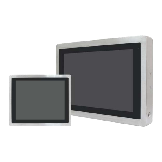
VITAM-9XXA Series
th
15", 15.6", 17", 19", 21.5", and 23.8" 6
Generation IP66/IP69K
Stainless Steel Panel PC
User Manual
Release Date
Revision
May 2020
V1.8
®2020 Aplex Technology, Inc.
All Rights Reserved.
Published in Taiwan
Aplex Technology, Inc.
15F-1, No.186, Jian Yi Road, Zhonghe District, New Taipei City 235, Taiwan
Tel: 886-2-82262881 Fax: 886-2-82262883
URL:
http://www.aplextec.com/zh/home.php
Advertisement
Table of Contents

Subscribe to Our Youtube Channel
Related Manuals for Aplex ViTAM-924A


Summary of Contents for Aplex ViTAM-924A
- Page 1 Stainless Steel Panel PC User Manual Release Date Revision May 2020 V1.8 ®2020 Aplex Technology, Inc. All Rights Reserved. Published in Taiwan Aplex Technology, Inc. 15F-1, No.186, Jian Yi Road, Zhonghe District, New Taipei City 235, Taiwan Tel: 886-2-82262881 Fax: 886-2-82262883 URL: http://www.aplextec.com/zh/home.php...
- Page 2 Revision History Reversion Date Description 2017/10/11 Official Version 2017/11/07 Add UPS battery 2018/01/29 Modify OS status/High brightness description 2018/11/01 Modify Operating temperature 2018/11/23 Revise Backlight Lifetime information 2019/06/27 Revise1.1 Specification data 2019/08/06 Add Logistic Statement 2020/01/02 Revise SBC-7114 Information 2020/05/26 Revise 1.1 specification data VITAM-9XXA Series User Manual...
- Page 3 This information in this document is subject to change without notice. In no event shall Aplex Technology Inc. be liable for damages of any kind, whether incidental or consequential, arising from either the use or misuse of information in this document or in any related materials.
-
Page 4: Packing List
Packing List Accessories (as ticked) included in this package are: □ Adaptor □ Driver & manual CD disc □ Other.___________________(please specify) VITAM-9XXA Series User Manual... -
Page 5: Safety Precautions
Safety Precautions Follow the messages below to prevent your systems from damage: ◆ Avoid your system from static electricity on all occasions. ◆ Prevent electric shock. Don‘t touch any components of this card when the card is power-on. Always disconnect power when the system is not in use. - Page 6 Dear Valued Partners Thank you for supporting APLEX Technology. Kindly note for ViTAM series, the pressure testing screw is loosen for half turn before shipment. The purpose is to avoid potential quality concerns caused by radical air pressure change during transportation. This especially applies to air shipment with unpressurized cabin.
-
Page 7: Table Of Contents
Table of Contents Revision History…………………………………………………………………………………………………….1 Warning!/Caution/Disclaimer..........…………………………….…2 Packing List…………………………………….……………………………………………………………………..3 Safety Precautions…………………………………………………………………….…..……………………..4 Logistic Statement…………………………………………………………………….…..……………………..5 Chapter 1 Getting Started 1.1 Features………………………..………………………...…………………………..7 1.2 Specifications…………………...………………………………………………….7 1.3 Dimensions………………………..…………………………………………….11 1.4 Brief Description of VITAM-9XXA Series………...…….……….……14 1.5 Yoke Mounting and VESA Mounting……………………………………15 Chapter 2 Hardware 2.1 Motherboard Introduction……………………...……………..………..16 2.2 Specifications…………………………..…………………………………………16 2.3 Jumpers and Connectors Location……………………………………...20 2.4 Jumpers Setting and Connectors…………………………………..……21... - Page 8 Chapter 5 Touch Screen Installation 5.1 Windows 8.1/10 Universal Driver Installation…….……..115 5.2 Software Function……………………………………………….……..119 Figures Figure 1.1: Dimensions of VITAM-915AP/R/G(H)…………..……………………11 Figure 1.2: Dimensions of VITAM-916AP/R/G(H)…….……….…………………11 Figure 1.3: Dimensions of VITAM-917AP/R/G(H)……..….…..…………………12 Figure 1.4: Dimensions of VITAM-919AP/R/G(H)…….……….…………………12 Figure 1.5: Dimensions of VITAM-921AP/R/G(H)……...……………………….13 Figure 1.6: Dimensions of VITAM-924AP/G(H)……..…….……………………..13 Figure 1.7: Front View and Touch on/off Button of VITAM-9XXA Serie.14 Figure 1.8: Rear View of VITAM-9XXA Series…..……….……..…………….….14...
-
Page 9: Getting Started
Chapter 1 Getting Started 1.1 Features 15”/15.6”/17”/19”/21.5”/23.8” New Gen. stainless steel panel PC Gen. Intel Core i3/i5 BGA type processor True flat front bezel design and Grade 304 Stainless Steel enclosure (Grade 316 for option) IP66/IP69K rated with M12 connectors ... - Page 10 with waterproof cover and chain Pin Define 1 x M12 8-pin for LAN with waterproof cover and chain LAN: Pin Define LAN1_0+ LAN1_0- LAN1_1+ LAN1_1- LAN1_2+ LAN1_2- LAN1_3+ LAN1_3- Power 1 x M12 3-pin for DC power with waterproof cover and chain Pin Define Others...
- Page 11 2 x USB 2.0 1 x USB 3.0 Option 1 x LAN (POE for option) 1 x COM 1 x CAN Storage Space Storage 1 x 2.5” SATA3 HDD Expansion Expansion Slot 1 x Mini PCIe slot for WIFI/BT and Antenna at rear side (option) RFID module RFID module design on the front side (option) Display –...
- Page 12 Interface Light Transmission Resistive touch window: over 80% Projected capacitive touch screen: over 90% Glass Type Type Light Transmission Over 90% Power Power Input DC 9~36V Power Consumption MAX:TBD MAX:TBD MAX:TBD MAX:TBD MAX:TBD MAX:53W (915AR) (916AR) (917AR) (919AR) (921AR) (924AP) MAX:35W MAX:49W MAX:49W...
-
Page 13: Dimensions
1.3 Dimensions Figure 1.1: Dimensions of VITAM-915AP/R/G(H) Figure 1.2: Dimensions of VITAM-916AP/R/G(H) VITAM-9XXA Series User Manual... -
Page 14: Figure 1.3: Dimensions Of Vitam-917Ap/R/G(H)
Figure 1.3: Dimensions of VITAM-917AP/R/G(H) Figure 1.4: Dimensions of VITAM-919AP/R/G(H) VITAM-9XXA Series User Manual... -
Page 15: Figure 1.5: Dimensions Of Vitam-921Ap/R/G(H)
Figure 1.5: Dimensions of VITAM-921AP/R/G(H) Figure 1.6: Dimensions of VITAM-924AP/G(H) VITAM-9XXA Series User Manual... -
Page 16: Brief Description Of Vitam-9Xxa Series
1.4 Brief Description of VITAM-9XXA Series There are 15”, 15.6”, 17”, 19”, 21.5”, and 24” new generation adopt the SUS304 grade stainless steel housing (SUS316 grade for option) panel PC in VITAM-9XXA series, which comes with 100% dust and waterproof guarantee, and the all-in-one fanless design. -
Page 17: Yoke Mounting And Vesa Mounting
1.5 Yoke Mounting and VESA Mounting The VITAM-9XXA Series model can be Yoke mounted and VESA mounted as shown in Picture below. Figure 1.9: Yoke mounting of VITAM-9XXA Series Figure 1.10: VESA mounting of VITAM-9XXA Series VITAM-9XXA Series User Manual... -
Page 18: Chapter 2 Hardware
Chapter 2 Hardware 2.1 Motherboard Introduction SBC-7114 is a 4" industrial motherboard developed on the basis of Intel Skylake-U Processor, which provides abundant peripheral interfaces to meet the needs of different customers. Also, it features dual GbE ports, 6-COM ports and one mSATA configuration, one HDMI port, and one LVDS interface. - Page 19 HDMI + DP1 (option) LVDS + DP1 (option) HDMI + LVDS + DP1 (option) Super I/O Nuvoton NCT6106D BIOS AMI/UEFI Storage 1 x SATAIII Connector (7P) 1 x SATAIII Connector (7P+15P) 1 x MSATA Connector (option) Ethernet 2 x PCIe GbE LAN by Intel I210-AT 2 x USB 3.0 (type A)stack ports (USB3) (USB3.0:USB3-1/USB3-2,USB2.0:USB1/USB2)
- Page 20 Support Line-in, Line-out, MIC by 2x6-pin header(AUDIO2) Support a stereo Class-D Speaker Amplifier with 2 watt per channel output power, by 1x4-pin header (SPK1) Expansion Bus 1 x mini-PCI-express slot (MPCIE or MSATA. Default: MSATA) 1 x PCI-express for CN3 2 x PCI-express for CN3 (PCIe 1x or USB3.0, Default:PCIe 1x) Infineon’s Trusted Platform Module (TPM2.0) *Note: Only support Windows 10 IOT*...
-
Page 21: Figure 2.1: Motherboard Dimensions
(Unit: mm) Figure 2.1: Motherboard Dimensions VITAM-9XXA Series User Manual... -
Page 22: Jumpers And Connectors Location
2.3 Jumpers and Connectors Location Figure 2.2: Jumpers and Connectors Location- Board Top Figure 2.3: Jumpers and Connectors Location- Board Bottom VITAM-9XXA Series User Manual... -
Page 23: Jumpers Setting And Connectors
2.4 Jumpers Setting and Connectors 1. CPU1: (FCBGA1356), onboard Intel Skylake-U processors Processor Model Number Cores/ Embedded Remarks Threads SBC-7114-I3-6100U I3-6100U 2.30GHz 2 / 4 ● SBC-7114-I3-6100UP I3-6100U 2.30GHz 2 / 4 ● option SBC-7114-I5-6300U I5-6300U 2.4 up to 3.0GHz 2 / 4 ●... - Page 24 2. H1/H2/H3/H4 (option): CPU1 Heat Sink Screw holes, four screw holes for Intel Skylake-U/ Kaby Lake Processors. Heat Sink assembles. 3. FAN1: (2.54mm Pitch 1x3 Pin Header), Fan connector, cooling fans can be connected directly for use. You may set the rotation condition of cooling fan in menu of BIOS CMOS Setup.
- Page 25 Pin# Signal Name Pin1 Ground PIN2 VBAT Procedures of CMOS clear: a) Turn off the system and unplug the power cord from the power outlet. b) Remove the lithium battery connection from BAT3 for 10 seconds, and then connect it. c) Power on the system again.
- Page 26 8. J_POE1: (2.0mm Pitch 1x2 Wafer Pin Header), POE or DCIN input setting. J_POE1 (Jumper) DC_IN1 BAT2 Pin1-Pin2(open,Default) ● Pin1-Pin2(Close) ● 9. BAT_LED1: (2.0mm Pitch 1x4 Wafer Pin Header), The Charge status indicator for BAT2 Pin1-Pin3: Charge LED status. Pin2-Pin3: Discharge LED status. Pin4-Pin3: This is reserved for LVDS MCU IC reset.
- Page 27 SBC-7114-I5-6300UP 45°Connector SBC-7114-I7-6600UP 45°Connector SBC-7114-3955UP 45°Connector SBC-7114-3965UP 45°Connector SBC-7114-I3-7100UP 45°Connector SBC-7114-I5-7300UP 45°Connector SBC-7114-I7-7600UP 45°Connector Connector Power input DC_IN1 (Default) DC_IN1 BAT2 (option) BAT2 DC_IN1 + BAT2 (option) DC_IN1 11. P_SW1/BT1,BT2: Power on/off button, it is used to connect power switch button. The two pins are disconnected under normal condition.
- Page 28 S-1(Switch) Function (CN1) Pin3 (ON) Single channel LVDS Pin3(OFF) Dual channel LVDS (Default) Pin4(ON) 8/24 bit (Default) Pin4(OFF) 6/18 bit SEL-LCD-EDID (U17 or OPC-547 U2/U3) Pin6 (ON) Onboard EDID Pin6 (OFF) Panel EDID 14. U17: AT24C02-DIP8,The EEPROM IC(U17)is the set of LVDS resolution. If you need other resolution settings, please upgrade U17 data.
- Page 29 16. CN1: (1.25mm Pitch 2x20 Connector, DF13-40P), For 18/24-bit LVDS output connector, fully supported by Parad PS8625 (DP to LVDS), the interface features dual channel 24-bit output. Low Voltage Differential Signaling, A high speed, low power data transmission standard used for display connections to LCD panels. Function Signal Name Pin#...
- Page 30 Function Signal Name Pin# Signal Name Function 12V_S0 12V_S0 12V_S0 12V_S0 Ground Ground 5V_S0 5V_S0 3P3V_S0 3P3V_S0 CPU_CFG4 Ground DDI1_TX1_N DDI1_TX1_P Ground DDI1_TX2_N DDI1_TX0_N DDI1_TX2_P DDI1_TX0_P Ground Ground DDI_TX3_N DDI1_AUX_N DDI_TX3_P DDI1_AUX_P I2C1_SCL EDP_HP_CN I2C1_SDA Ground Ground USB7 (option) USB7 USB7_P USB7_N (option)
- Page 31 TCH1(Disable) Open 1(Default) TCH1(Enable) Open TCH1(Disable) Open 20. TCH1: (2.0mm Pitch 1x6 wafer Pin Header), internal touch controller connector. Pin# Signal Name SENSE GND_EARCH 21. LED1: LED1: LED STATUS. Green LED for touch power status. 22. JP1: (2.0mm Pitch 2x3 Pin Header), COM1 jumper setting, pin 1~6 are used to select signal out of pin 9 of COM1 port.
- Page 32 RS232 (Default): Pin# Signal Name DCD# (Data Carrier Detect) RXD (Received Data) TXD (Transmit Data) DTR (Data Terminal Ready) Ground DSR (Data Set Ready) RTS (Request To Send) CTS (Clear To Send) JP1 select Setting (RI/5V/12V) BIOS Setup: Advanced/NCT6106D Super IO Configuration/F75111 COM1 Configuration【RS-232】...
- Page 33 BIOS Setup: Advanced/NCT6106D Super IO Configuration/F75111 COM1 Configuration【RS-485】 24. JP2: (2.0mm Pitch 2x3 Pin Header), COM2 jumper setting, pin 1~6 are used to select signal out of pin 9 of COM2 port. JP2 Pin# Function Close 1-2 COM2 RI (Ring Indicator) (default) COM2 Pin9:DC+5V (option) Close 3-4...
- Page 34 Pin# Signal Name 5V_S0 (+DC5V output) Ground Note: Output current of the connector must not be above 1A. 27. SATA2: (SATA 7Pin), SATA Connectors, one SATA connector is provided with transfer speed up to 6.0 Gb/s. 28. SATA1: (SATA 7Pin+15Pin), SATA Connectors, one SATA connector is provided; with transfer speed up to 6.0Gb/s.
- Page 35 32. AUDIO2: (2.0mm Pitch 2X6 Pin Header), Front Audio, An onboard Realtek ALC269Q codec is used to provide high-quality audio I/O ports. Line Out can be connected to a headphone or amplifier. Line In is used for the connection of external audio source via a Line in cable.
- Page 36 36. LAN1/LAN2: LAN1/LAN2: (RJ45 Connector), Rear LAN port, Two standard 10/100/1000M RJ-45 Ethernet ports are provided. Use Intel 82574L chipset, LINK LED (green) and ACTIVE LED (green) respectively located at the left-hand and right-hand side of the Ethernet port indicate the activity and transmission state of LAN. 37.
- Page 37 39. EC_GPIO1: (2.0mm Pitch 1X10 Pin Header),For expand connector ,It provides eight GPIO. Pin# Signal Name GPIO Name Ground Ground GPA0_ONOFF EC_GPA0 GPA1_SPK EC_GPA1 GPE6_BKLT EC_GPE6 GPE0_BKLT+ EC_GPE0 GPH3_SPK+ EC_GPH3 BKLT_CTRL_PWR BKLT_CTRL_PWR ADC6_BKLT_CTRL EC_ADC6 ADC7_RSV EC_ADC7 3.3V_ALLS_EC 3.3V_ALLS_EC 40. CN3: (1.27mm Pitch 2X50 Female Header),for expand output connector, it provides four...
- Page 38 (UART) COM3_DTR COM3_RTS- (UART) COM3_DSR COM3_CTS- GPPC20 PCH_GPPC20 PCH_GPPC22 GPPC22 GPPC21 PCH_GPPC21 PCH_GPPC23 GPPC23 Ground Ground PCIE4_TX_N0 PE4_TX_P0 PCIE4_RX_N0 PE4_RX_P0 PCIE4 PCIE1 Ground Ground CLK_100M_PE4_N CLK_100M_PE4_P PCIE4_WAKE_N PLT_RST_BUF2- SMBUS SMB_CLK_S5 SMB_DATA_S5 SMBUS PCIE CLKREQ_PE4- Ground 3P3V_S5 PWRBTN_ON- Power Auto 3P3V_S5 3P3V_S5 12V_S0 12V_S0...
- Page 39 41. TPM_U1(option): Infineon’s Trusted Platform Module (TPM2.0) SLB9665 is a fully standard compliant TPM based on the latest Trusted Computing Group (TCG) specification 2.0. *Note: Only support Windows 10 IOT* TPM_U1 SLB 9665 TT2.0 MODEL TPM Function ● SBC-7114-XXX R2.30 SBC-7114-XXX R2.20 SBC-7114-XXX R1XX 42.
- Page 40 Signal Name Function support PCIe 1X USB2.0 (USB2) SMBus H1/H2: MPCIE1 SCREW HOLES, H2 for mini PCIE card (30mmx30mm) assemble. H1 for mini PCIE card (30mmx50.95mm) assemble. LED1: Mini PCIe devices LED Status SIM1: (SIM Socket 6 Pin), Support SIM Card devices SIM2 (option):...
- Page 41 Signal Name Pin# Pin# Signal Name 5V_USB12 5V_USB12 E_USB1_N E_USB2_N E_USB1_P E_USB2_P Ground Ground Ground Note: Before connection, make sure that pinout of the USB Cable is in accordance with that of the said tables. Any inconformity may cause system down and even hardware damages.
- Page 42 CTS (Clear To Send) JP5 Setting: Pin1-2 : RI (Ring Indicator) (default) Pin3-4 : 5V Standby power (option) Pin5-6:12V Standby power (option) COM_5: (2.0mm Pitch 2x5 Pin Header), COM5 port, up to one standard RS232 port is provided. It can be used directly via COM cable connection. Signal Name Pin# Pin#...
- Page 43 DTR (Data Terminal Ready) Ground DSR (Data Set Ready) RTS (Request To Send) CTS (Clear To Send) JP6 Setting: Pin1-2 : RI (Ring Indicator) (default) Pin3-4 : 5V Standby power (option) Pin5-6:12V Standby power (option) COM_6: (2.0mm Pitch 2X5 Pin Header), COM6 Port, up to one standard RS232 port is provided.
- Page 44 TB-528CAN2 Top: CN3: (1.27mm Pitch 2X30 Pin Header),connect to SBC-7114 CN3 pin Header. M-PCIE1: (Socket 52Pin), mini PCIe socket, it is located at the top, it supports mini PCIe devices with SMbus, USB2.0, SIM and PCIe signal. MPCIe card size is 30x30mm or 30x50.95mm.
- Page 45 (SIM Socket 6 Pin), Support SIM Card devices. PS2: (2.0mm Pitch 1x6 Pin Wafer), PS/2 keyboard and mouse port, the port can be connected to PS/2 keyboard or mouse via a dedicated cable for direct use. Pin# Signal Name KBDATA MSDATA Ground KBCLK...
- Page 46 PSON_ATX Ground JP6: (2.0mm Pitch 2x3 Pin Header) COM6 setting jumper, pin1~6 are used to select signal out of pin9 of COM6 port. JP6 Pin# Function Close 1-2 RI (Ring Indicator) (default) COM6 Pin9:+5V (option) Close 3-4 COM6 Pin9:+12V (option) Close 5-6 COM6(SBC-7114/COM4):...
- Page 47 SMB_CLK_R PCH-GPIO56 PCH-GPIO57 PCH-GPIO58 PCH-GPIO58 JTAG: (2.0mm Pitch 2x5 Pin Header), Reserve JP1: (2.0mm Pitch 1x2 Pin Header), Reserve JP2: (2.0mm Pitch 1x2 Pin Header), Reserve CAN1/CAN2: (3.5mm Pitch 1x10 Pin connector), it provides two CAN-bus interfaces. Pin# Channel Signal Name Function CANL2 CAN bus Signal L...
- Page 48 CN3: (1.27mm Pitch 2X30 Pin Header), connect to SBC-7118 CN2 pin Header. USB23 (SBC-7114 USB3/USB4): (Double stack USB type A), Rear USB connector, it provides up to 2 USB2.0 ports, speed up to 480Mb/s. LAN1: (RJ45 Connector), Rear LAN port, one standard 10/100/1000M RJ-45 Ehternet port is provided.
- Page 49 (3.96mm Pitch 1x2 Pin Header), POE DC 12V Output. Pin# Output Voltage 12V_POE Ground Model Maximum Output SBC-7114 Power ● TB-528E1UPOE AG5510 12V_OUT3 (option): (2.0mm Pitch 1x6 Pin Header), Reserve 12V_OUT1 (option): (3.96mm Pitch 1x2 Pin Header), Reserve JP3 (option): (2.0mm Pitch 1x3 Pin Header), Reserve S1 (option): Reserve 45.
- Page 50 LVDS1: (1.25mm Pitch 2X20 connector, DF13-40P) Function Signal Name Pin# Signal Name Function 12V_S0 12V_S0 BKLT_CTRL BKLT_EN_OUT Ground Ground LVDS_VDD5 LVDS_VDD5 LVDS_VDD3 LVDS_VDD3 Ground Ground LA_D0_P LA_D0_N LVDS LVDS LA_D1_P LA_D1_N LA_D2_P LA_D2_N LA_D3_P LA_D3_N LA_CLKP LA_CLKN LB_D0_P LB_D0_N LB_D1_P LB_D1_N LB_D2_P LB_D2_N...
- Page 51 (2.0mm Pitch 1x6 wafer Pin Header), Backlight control connector for LVDS. Pin# Signal Name +DC12V_S0 +DC12V_S0 Ground Ground BKLT_EN_OUT BKLT_CTRL TOUCH1: (2.0mm Pitch 1x6 wafer Pin Header), internal Touch controller connector. Pin# Signal Name SENSE GND_EARCH JP6 (option): (2.0mm Pitch 2x5 Pin Header) LVDS EDID setting jumper JP6 Pin# Function (CN1) Close 1-2...
- Page 52 46. TB-547 R1.20(option): TB-548 Riser Card, TB-547 LVDS1 connects to LVDS panel, TB-547 INVT1 connects to LVDS panel, TB-547 TOUCH1 connects to TOUCH panel, TB-547 CON1 OPS connects to TB-548 CON1. TB-547 Top: TB-547 Bottom: LVDS1: (1.25mm Pitch 2X20 connector, DF13-40P) Function Signal Name Pin#...
- Page 53 Ground Ground LA_D0_P LA_D0_N LVDS LVDS LA_D1_P LA_D1_N LA_D2_P LA_D2_N LA_D3_P LA_D3_N LA_CLKP LA_CLKN LB_D0_P LB_D0_N LB_D1_P LB_D1_N LB_D2_P LB_D2_N LB_D3_P LB_D3_N LB_CLKP LB_CLKN USB7 Ground Ground (option) USB7_P USB7_N 5V_S5_USB 5V_S5_USB PWR_LED+ Ground Power LED INVT1: (2.0mm Pitch 1x6 wafer Pin Header), backlight control connector for LVDS. Pin# Signal Name +DC12V_S0...
- Page 54 GND_EARCH S_1 (PIN3) : (Switch), LVDS EDID setting jumper S_1(Switch) Function (LVDS) Single channel LVDS Pin1(ON) Pin1(OFF) Dual channel LVDS Pin2(ON) 8/24 bit Pin2(OFF) 6/18 bit SEL-LCD-EDID (SBC-7114 U17 or OPC-547 U2/U3) Panel EDID Pin3(ON) Onboard EDID Pin3(OFF) Pin4 Pin5 This setting can only select SBC-7114 R2.XX S_1 or TB-547 S_1.
-
Page 55: Bios Setup
Chapter 3 BIOS Setup 3.1 Operations after POST Screen After CMOS discharge or BIOS flashing operation, press [Delete] key to enter CMOS Setup. After optimizing and exiting CMOS Setup 3.2 BIOS Setup Utility Press [Delete] key to enter BIOS Setup utility during POST, and then a main menu containing system summary information will appear. -
Page 56: Main Settings
3.3 Main Settings System Time: Set the system time, the time format is: Hour : 0 to 23 Minute : 0 to 59 Second : 0 to 59 VITAM-9XXA Series User Manual... -
Page 57: Advanced Settings
System Date: Set the system date, the date format is: Day: Note that the ‘Day’ automatically changes when you set the date. Month: 01 to 12 Date: 01 to 31 Year: 1998 to 2099 3.4 Advanced Settings 3.4.1 ACPI Settings Enable ACPI Auto Configuration: [Disabled] [Enabled]... - Page 58 [S3 (Suspend to RAM) ] [Suspend Disabled] Lock Legacy Resources: [Disabled] [Enabled] S3 Video Repost: [Disabled] [Enabled] ACPI Low Power S0 Idle: [Disabled] [Enabled] 3.4.2 AMT Configuration Intel AMT [Disabled] BIOS Hotkey Pressed [Disabled] MEBx Selection Screen [Disabled] Hide Un-Configure ME Configuration [Disabled] Prompt MEBx Debug Message Output...
- Page 59 IO=3F8h ; IRQ=4 ; Device Settings Change Settings [Auto] F75111 COM1 Config [RS-232 Mode] [RS-485 Mode] [RS-422 Mode] Serial Port 2 Configuration Serial port [Enabled] [Disabled] IO=2F8h ; IRQ=3 ; Device Settings Change Settings [Auto] Serial Port 3 Configuration Serial port [Enabled] [Disabled] IO=3E8h ;...
- Page 60 Device Settings IO=2E0h; IRQ=7; Change Settings [Auto] COM6 Config [RS-485 Mode] [RS-422 Mode] Power Failure [Power OFF] [Power ON] [Last state] 3.4.4 NCT6106D HW Monitor Pc Health Status :38 CPU Temperature :N/A CPU Fan Speed :+0.872V VCORE :+11.864V :+5.299V :+3.472V VCC3V 3.4.5 IT8528SEC Super IO Configuration EC VERSION...
- Page 61 CPU C8 state Supported CPU C9 state Supported CPU C10 state Supported L1 Date Cache 32KB x 2 L1 Code Cache 32KB x 2 L2 Cache 256 KB x 2 L3 Cache 3 MB L4 Cache Not Present Hyper-threading [Enabled] Active Processor Cores [All] Overclocking lock...
- Page 62 Power Limit 3 Override [Disabled] ►Power Limit 4 Settings Power Limit 4 Override [Disabled] ►CPU Thermal Configuration CPU DTS [Disabled] TCC Activation Offset ACPI 3.0 T-States [Disabled] Debug Interface [Disabled] Debug Interface Lock [Enabled] SW Guard Extensions(SGX) [Software Controlled] Select Owner EPOCH input type [No Change In Owner EPOCHS] PRMRR Size [AUTO]...
- Page 63 Pmic Vddq Level [Disabled] Power Sharing Manager [Disabled] Select Camera [IVCAM] Enable 3D Camera DFU device [Disabled] Wireless device [Disabled] WRDS Package WiFi SAR [Disabled] HID Event Filter Driver [Disabled] Enable Wireless Charge Support [Disabled] Enable FFU Support [Disabled] 3.4.8 SATA Configuration SATA Controller (S)...
- Page 64 Topology [Unknown] Device Sleep [Disabled] SATA DEVSLEP Idle Timeout Config [Disabled] Serial ATA Port 2 Empty Software Preserve Unknown Port 2 [Enabled] Hot Plug [Disabled] External SATA [Disabled] Spin Up Device [Disabled] SATA Device Type [Hard Disk Drive] Topology [Unknown] Device Sleep [Disabled] SATA DEVSLEP Idle Timeout Config...
- Page 65 Software Preserve Unknown Port 5 [Enabled] Hot Plug [Disabled] External SATA [Disabled] Spin Up Device [Disabled] SATA Device Type [Hard Disk Drive] Topology [Unknown] Device Sleep [Disabled] SATA DEVSLEP Idle Timeout Config [Disabled] 3.4.9 CSM Configuration Compatibility Support Module Configuration CSM Support [Enabled] CSM16 Module Version...
-
Page 66: Chipset Settings
Legacy USB Support [Enabled] XHCI Hand-off [Enabled] USB Mass Storage Driver Support [Enabled] Port 60/64 Emulation [Disabled] USB Hardware delays and time-outs: USB transfer time-out [20 sec] Device reset time-out [20 sec] Device power-up delay [Auto] 3.5 Chipset Settings 3.5.1 System Agent (SA) Configuration System Agent Bridge Name Skylake SA PCIe Code Version... - Page 67 Panel Color Depth [18 Bit] LCD Backlight Control [PWM Normal by BIOS] BIOS Control Backlight Level [Level 7] ►Graphics Configuration IGFX VBIOS Version 1046 Graphics Turbo IMON Current Skip Scanning of External Gfx Card [Disabled] Primary Display [Auto] Primary PEG [Auto] Primary PCIE [Auto]...
- Page 68 DIMM#3 Not Present Memory Timings(tCL-tRCD-tRP-tRAS) 5-36 MRC ULT Safe Conifg [Disabled] Maximum Memory Frequency [Auto] HOB Buffer Size [Auto] ECC Support [Enabled] Max TOLUD [Dynamic] LCD Backlight Mode [PWM] Backlight Control [PWM Normal by BIOS] BIOS Control Backlight Level [Level 7] SA GV [Enabled] SA GV Low Freq...
- Page 69 EV Loader [Disabled] EV Loader Delay [Enabled] Fast Boot [Enabled] DLL Weak Lock Support [Enabled] ►Memory Thermal Configuration ►Memory Power and Thermal Throttling DDR PowerDown and idle counter [BIOS] For LPDDR Only:DDR PowerDown and idle counter [BIOS] REFRESH_2X_MODE [Disabled] LPDDR Thermal Sensor [Enabled] SelfRefresh Enable [Enabled]...
- Page 70 PowerDown Energy Ch1Dimm0 Activate Energy Ch1Dimm0 Read Energy Ch1Dimm0 Write Energy Ch1Dimm0 Idle Energy Ch1Dimm0 PowerDown Energy Ch1Dimm0 Activate Energy Ch1Dimm0 Read Energy Ch1Dimm0 Write Energy Ch1Dimm0 Idle Energy Ch1Dimm1 PowerDown Energy Ch1Dimm1 Activate Energy Ch1Dimm1 Read Energy Ch1Dimm1 Write Energy Ch1Dimm1 ►Memory Thermal Reporting Lock Thermal:Management Registers Enabled]...
- Page 71 Warm Budget Ch0 Dimm0 Warm Budget Ch0 Dimm1 Hot Budget Ch0 Dimm0 Hot Budget Ch0 Dimm1 Warm Budget Ch1 Dimm0 Warm Budget Ch1 Dimm1 Hot Budget Ch1 Dimm0 Hot Budget Ch1 Dimm1 ►Memory RAPL Rapl Power Floor Ch0 Rapl Power Floor Ch1 RAPL PL Lock [Disabled] RAPL PL 1 enable...
- Page 72 Max RTT_WR [ODT Off] DIMM RON Training* [Enabled] Write Drive Strength/Equalization 2D* [Disabled] Write Slew Rate Training* [Enabled] Read ODT Training* [Enabled] Read Equalization Training* [Enabled] Read Amplifier Training* [Enabled] Write Timing Centering 2D [Enabled] Read Timing Centering 2D [Enabled] Command Voltage Centering [Enabled] Write Voltage Centering...
- Page 73 Peer Memory Write Enable [Disabled] Compliance Test Mode [Disabled] PCIe-USB Glitch W/A [Disabled] PCIe function swap [Enabled] ►PCI Express Gen3 Eq Lanes Override SW EQ Settings [Disabled] ►PCI Express Root Port 1 PCI Express Root Port 1 [Enabled] Topology [Unknown] ASPM Support [Auto] L1 SubStates...
- Page 74 PCH PCIe CLKREQ# Configuration PCIE1 CLKREQ Mapping Override [Default] Snoop Latency Ocerride [Auto] Non Snoop Latency Ocerride [Auto] ►PCI Express Root Port 2 PCI Express Root Port 2 [Enabled] Topology [Unknown] ASPM Support [Auto] L1 SubStates [L1.1&L1.2] Gen3 Eq Phase3 Method [Software Search] UPTP DPTP...
- Page 75 PCIE2 CLKREQ Mapping Override [Default] Snoop Latency Ocerride [Auto] Non Snoop Latency Ocerride [Auto] ►PCI Express Root Port 3 PCI Express Root Port 3 [Enabled] Topology [Unknown] ASPM Support [Auto] L1 SubStates [L1.1&L1.2] Gen3 Eq Phase3 Method [Software Search] UPTP DPTP [Enabled] [Disabled]...
- Page 76 Non Snoop Latency Ocerride [Auto] ►PCI Express Root Port 4 PCI Express Root Port 4 [Enabled] Topology [Unknown] ASPM Support [Auto] L1 SubStates [L1.1&L1.2] Gen3 Eq Phase3 Method [Software Search] UPTP DPTP [Enabled] [Disabled] [Disabled] NFER [Disabled] [Disabled] [Disabled] SEFE [Disabled] SENFE [Disabled]...
- Page 77 ►PCI Express Root Port 5 PCI Express Root Port 5 [Enabled] Topology [Unknown] ASPM Support [Auto] L1 SubStates [L1.1&L1.2] Gen3 Eq Phase3 Method [Software Search] UPTP DPTP [Enabled] [Disabled] [Disabled] NFER [Disabled] [Disabled] [Disabled] SEFE [Disabled] SENFE [Disabled] SECE [Disabled] PME SCI [Enabled] Hot Plug...
- Page 78 Topology [Unknown] ASPM Support [Auto] L1 SubStates [L1.1&L1.2] Gen3 Eq Phase3 Method [Software Search] UPTP DPTP [Enabled] [Disabled] [Disabled] NFER [Disabled] [Disabled] [Disabled] SEFE [Disabled] SENFE [Disabled] SECE [Disabled] PME SCI [Enabled] Hot Plug [Disabled] Advanced Error Reporting [Enabled] PCIe Speed [Auto] Transmitter Half Swing [Disabled]...
- Page 79 ASPM Support [Auto] L1 SubStates [L1.1&L1.2] Gen3 Eq Phase3 Method [Software Search] UPTP DPTP [Enabled] [Disabled] [Disabled] NFER [Disabled] [Disabled] [Disabled] SEFE [Disabled] SENFE [Disabled] SECE [Disabled] PME SCI [Enabled] Hot Plug [Disabled] Advanced Error Reporting [Enabled] PCIe Speed [Auto] Transmitter Half Swing [Disabled] Detect Non-Compliance Device...
- Page 80 L1 SubStates [L1.1&L1.2] Gen3 Eq Phase3 Method [Software Search] UPTP DPTP [Enabled] [Disabled] [Disabled] NFER [Disabled] [Disabled] [Disabled] SEFE [Disabled] SENFE [Disabled] SECE [Disabled] PME SCI [Enabled] Hot Plug [Disabled] Advanced Error Reporting [Enabled] PCIe Speed [Auto] Transmitter Half Swing [Disabled] Detect Non-Compliance Device [Disabled]...
- Page 81 Gen3 Eq Phase3 Method [Software Search] UPTP DPTP [Enabled] [Disabled] [Disabled] NFER [Disabled] [Disabled] [Disabled] SEFE [Disabled] SENFE [Disabled] SECE [Disabled] PME SCI [Enabled] Hot Plug [Disabled] Advanced Error Reporting [Enabled] PCIe Speed [Auto] Transmitter Half Swing [Disabled] Detect Non-Compliance Device [Disabled] Extra Bus Reserved Reserved Memory...
- Page 82 DPTP [Enabled] [Disabled] [Disabled] NFER [Disabled] [Disabled] [Disabled] SEFE [Disabled] SENFE [Disabled] SECE [Disabled] PME SCI [Enabled] Hot Plug [Disabled] Advanced Error Reporting [Enabled] PCIe Speed [Auto] Transmitter Half Swing [Disabled] Detect Non-Compliance Device [Disabled] Extra Bus Reserved Reserved Memory Prefetchable Memory Reserved I/O PCIE Cp...
- Page 83 [Enabled] [Disabled] [Disabled] NFER [Disabled] [Disabled] [Disabled] SEFE [Disabled] SENFE [Disabled] SECE [Disabled] PME SCI [Enabled] Hot Plug [Disabled] Advanced Error Reporting [Enabled] PCIe Speed [Auto] Transmitter Half Swing [Disabled] Detect Non-Compliance Device [Disabled] Extra Bus Reserved Reserved Memory Prefetchable Memory Reserved I/O PCIE Cp PCIE Cm...
- Page 84 [Disabled] [Disabled] NFER [Disabled] [Disabled] [Disabled] SEFE [Disabled] SENFE [Disabled] SECE [Disabled] PME SCI [Enabled] Hot Plug [Disabled] Advanced Error Reporting [Enabled] PCIe Speed [Auto] Transmitter Half Swing [Disabled] Detect Non-Compliance Device [Disabled] Extra Bus Reserved Reserved Memory Prefetchable Memory Reserved I/O PCIE Cp PCIE Cm...
- Page 85 Audio DSP [Disabled] HDA-Link Codec Select [Platform Onboard] iDisplay Audio Disconnect [Disabled] PME Enable [Disabled] ►HD Audio Advanced Configuration HD Audio Subsystem Advanced Configuration Settings I/O Buffer Control: I/O Buffer Ownership [HD-Audio Link] I/O Buffer Voltage Select [3.3V] Statically Switchable BCLK Clock Frequency Configuration: HD Audio Link Frequency [24MHz]...
- Page 86 Dolby [Disabled] ForteMedia SAMSoft [Disabled] Intel WoV [Disabled] Sound Research IP [Disabled] Conexant Pre-Process [Disabled] Conexant Smart Amp [Disabled] Custom Module ’Alpha’ [Disabled] Custom Module ‘Beta’ [Disabled] Custom Module ‘Gamma’ [Disabled] ►Serial IO Configuration Touch Panel [SPI Touch] BT/UART Mux Select [UART Signal] I2C0 Controller [Disabled]...
- Page 87 Control Logic 1 [Disabled] Control Logic 2 [Disabled] Control Logic 3 [Disabled] Link0 [Disabled] Link1 [Disabled] Link2 [Disabled] Link3 [Disabled] PORT-A HS-RXEN/TEM-EN Override [Disabled] PORT-B HS-RXEN/TEM-EN Override [Disabled] PORT-C HS-RXEN/TEM-EN Override [Disabled] PORT-D HS-RXEN/TEM-EN Override [Disabled] PORT-A CTLE [Enabled] PORT-B CTLE [Enabled] PORT-C/D CTLE [Enabled]...
- Page 88 ►ISH Configuration ISH Controller [Disabled] PDT Unlock Message [Disabled] ►TraceHub Configuration Menu TraceHub Enabled Mode [Disabled] MemRegion 0 Buffer Size [1MB] MemRegion 1 Buffer Size [1MB] ►Pch Thermal Throttling Control Thermal Throttling Level [Suggested Setting] DMI Thermal Setting [Suggested Setting] SATA Thermal Setting [Suggested Setting] ►SB Porting Configuration...
- Page 89 Compatible Revision ID [Disabled] PCH Cross Throttling [Enabled] Disable Energy Reporting [Disabled] Capsule Reset Type [Capsule S3 Resume] Pcie Pll SSC [Auto] IOAPIC 24-119 Entries [Enabled] Unlock PCH P2SB [Disabled] PMC READ DISABLE [Enabled] VITAM-9XXA Series User Manual...
-
Page 90: Security Settings
3.6 Security Settings 3.6.1 Administrator Password 3.6.2 User Password Type the password with up to 20 characters and then press Enter key. This will clear all previously typed CMOS passwords. You will be requested to confirm the password. Type the password again and press Enter... - Page 91 enter BIOS setup. This will prevent unauthorized persons from changing your system configurations. Also, the feature is capable of requesting users to enter the password prior to system boot to control unauthorized access to your computer. Users may enable the feature in Security Option of Advanced BIOS Features.
-
Page 92: Boot Settings
3.7 Boot Settings Setup Prompt Timeout Bootup Numlock State [On] Quiet Boot [Disabled] Boot Option Priorities Fast Boot [Disabled] Driver Option Priorities New Boot Option Policy [Default] VITAM-9XXA Series User Manual... -
Page 93: Save & Exit Settings
3.8 Save & Exit Settings Save Changes and Exit Save & Exit Setup save Configuration and exit ? [Yes] [No] Discard Changes and Ext Exit Without Saving Quit without saving? [Yes] [No] Save Changes and Reset Reset the system affer Saving The changes? [Yes] [No] Discard Changes and Reset... - Page 94 Save Changes Save Setup done so far to any of the setup options? [Yes] [No] Discard Changes Discard Changes done so far to any of the setup options? [Yes] [No] Restore Defaults Restore /Load Defaults values for all the setup options? [Yes] [No] Save as user Defaults...
-
Page 95: Chapter 4 Installation Of Drivers
Chapter 4 Installation of Drivers This chapter describes the installation procedures for software and drivers under the windows 8.1 & 10. The software and drivers are included with the motherboard. The contents include Intel H170 , Graphics 530 chipset driver, Audio driver, Intel® management engine interface, and DPTF Driver Installation instructions are given below. -
Page 96: Intel H170 Chipset
4.1 Intel H170 Chipset To install the Intel H170 chipset driver, please follow the steps below. Step 1. Select Intel H170 Chipset from the list Step 2. Here is welcome page. Please make sure you save and exit all programs before install. - Page 97 Step3. Read the license agreement. Click Accept to accept all of the terms of the license agreement. Step4. Click Install to begin the installation. VITAM-9XXA Series User Manual...
- Page 98 Step5. Select Restart Now to reboot your computer for the changes to take effect. VITAM-9XXA Series User Manual...
-
Page 99: Intel® Hd Graphics 530 Chipset
4.2 Intel® HD Graphics 530 Chipset To install the Intel® HD Graphics 530 Chipset, please follow the steps below. Step 1. Select Intel® HD Graphics 530 Chipset from the list. Step2. Click Next. VITAM-9XXA Series User Manual... - Page 100 Step3. Choose automatically run function and Click Next to setup program. Step4. Read the license agreement. Click Yes to accept all of the terms of the license agreement. VITAM-9XXA Series User Manual...
- Page 101 Step5. Click Next to continue. Step6. Here is Intel product improvement program information, you can choose Accept or Decline by your option and installation will go to next step. VITAM-9XXA Series User Manual...
- Page 102 Step7. Click Next to continue the program. Step8. Select Yes, I want to restart this computer now. Click Finish to complete installation. VITAM-9XXA Series User Manual...
-
Page 103: Realtek Alc662 Hd Audio Driver Installation
4.3 Realtek ALC662 HD Audio Driver Installation To install the Realtek ALC662 HD Audio Driver, please follow the steps below. Step1. Select Realtek AL662 HD Audio Driver from the list Step2. Click Next to continue. VITAM-9XXA Series User Manual... - Page 104 Step3. Click Yes, I want to restart my computer now. Click Finish to complete the installation. VITAM-9XXA Series User Manual...
-
Page 105: Intel® Management Engine Interface
4.4 Intel® Management Engine Interface To install the Intel® Management Engine Interface, please follow the steps below. Step1. Select Intel® Management Engine Interface from the list Step2. Select setup language you need. Click Next to continue. Step3. Choose I accept the terms in the License Agreement and click Next to begin VITAM-9XXA Series User Manual... - Page 106 the installation. Step4. Click Next to continue. VITAM-9XXA Series User Manual...
- Page 107 Step5. Click Finish to complete the installation. VITAM-9XXA Series User Manual...
-
Page 108: Dptf Driver
4.5 DPTF Driver To install the DPTF Driver, please follow the steps below. Step1. Select DPTF Driver from the list Step2. Click Next to continue. VITAM-9XXA Series User Manual... - Page 109 Step3. Read the license agreement. Choose Accept and click Next to accept all of the terms of the license agreement. Step4. Select destination location by your option and click Next to continue. VITAM-9XXA Series User Manual...
- Page 110 Step5. Click Install to continue the installing. Step6. Click Finish to complete the installation and start install Intel DPTF driver for Windows. VITAM-9XXA Series User Manual...
- Page 111 Step7. Click Next to start the installation. Step8. Read the license agreement. Click Yes to accept all of the terms of the license agreement. Step9. Click Next to continue. VITAM-9XXA Series User Manual...
- Page 112 Step10. Click Finish to complete the installation. VITAM-9XXA Series User Manual...
-
Page 113: Chapter 5 Touch Screen Installation
Chapter 5 Touch Screen Installation This chapter describes how to install drivers and other software that will allow your touch screen work with different operating systems. 5.1 Windows 8.1/10 Universal Driver Installation for PenMount 6000 Series Before installing the Windows 8.1/10 driver software, you must have the Windows 8.1/10 system installed and running on your computer. - Page 114 Step2. Click Next to continue. Step3. Read the license agreement. Click I Agree to agree the license agreement. VITAM-9XXA Series User Manual...
- Page 115 Step4. Choose the folder in which to install PenMount Windows Universal Driver. Click Install to start the installation. Step5. Click Yes to continue. VITAM-9XXA Series User Manual...
- Page 116 Step6. Click Finish to complete installation. VITAM-9XXA Series User Manual...
-
Page 117: Software Function
5.2 Software Functions Resistive Touch Upon rebooting, the computer automatically finds the new 6000 controller board. The touch screen is connected but not calibrated. Follow the procedures below to carry out calibration. 1. After installation, click the PenMount Monitor icon “PM” in the menu bar. 2. - Page 118 Calibrate This function offers two ways to calibrate your touch screen. ‘Standard Calibration’ adjusts most touch screens. ‘Advanced Calibration’ adjusts aging touch screens. Standard Calibration Click this button and arrows appear pointing to red squares. Use your finger or stylus to touch the red squares in sequence.
- Page 119 Step2.Click “Standard Calibration” to start calibration procedure NOTE: The older the touch screen, the more Advanced Mode calibration points you need for an accurate calibration. Use a stylus during Advanced Calibration for greater accuracy. Please follow the step as below: VITAM-9XXA Series User Manual...
- Page 120 Step3. Select Device to calibrate, then you can start to do Advanced Calibration. NOTE: Recommend to use a stylus during Advanced Calibration for greater accuracy. Plot Calibration Data Check this function and a touch panel linearity comparison graph appears when you have finished Advanced Calibration.
- Page 121 Setting Touch Mode This mode enables and disables the mouse’s ability to drag on-screen icons – useful for configuring POS terminals. Mouse Emulation – Select this mode and the mouse functions as normal and allows dragging of icons. Click on Touch – Select this mode and mouse only provides a click function, and dragging is disables.
- Page 122 Edge Compensation You can use Edge Compensation to calibrate more subtly. About This panel displays information about the PenMount controller and driver version. VITAM-9XXA Series User Manual...
- Page 123 Multiple Monitors Multiple Monitors support from two to six touch screen displays for one system. The PenMount drivers for Windows 7/8/8.1 support Multiple Monitors. This function supports from two to six touch screen displays for one system. Each monitor requires its own PenMount touch screen control board, either installed inside the display or in a central unit.
- Page 124 4. Touching all screens completes the mapping and the desktop reappears on the monitors. 5. Select a display and execute the “Calibration” function. A message to start calibration appears. Click OK. 6. “Touch this screen to start its calibration” appears on one of the screens. Touch the screen.
- Page 125 About This panel displays information about the PenMount controller and this driver version. PenMount Monitor Menu Icon The PenMount monitor icon (PM) appears in the menu bar of Windows 7/8/8.1 system when you turn on PenMount Monitor in PenMount Utilities. PenMount Monitor has the following function Control Panel Open Control Panel Windows...
- Page 126 Configuring the Rotate Function 1. Install the rotation software package. 2. Choose the rotate function (0°, 90°, 180°, 270°) in the 3rd party software. The calibration screen appears automatically. Touch this point and rotation is mapped. NOTE: The Rotate function is disabled if you use Monitor Mapping VITAM-9XXA Series User Manual...
Need help?
Do you have a question about the ViTAM-924A and is the answer not in the manual?
Questions and answers