Table of Contents
Advertisement
User Manual
Power Conversion System (PCS)
SC1200UD-US/SC1375UD-US/SC1575UD-US/SC1725UD-
US/SC2000UD-US/SC2500UD-US
SC1200UD-US/SC1375UD-US/
Power
SC1575UD-US/SC1725UD-US/SC2000UD-US/SC2500UD-US
Conversion System (PCS)User
M-H-002023
SC1200_1375_1575_1725_2000_2500UD-US-UEN-Ver112-202311
SC1200_1375_1575_1725_2000_2500UD-US-UEN-Ver112-202311
Advertisement
Table of Contents

Related Manuals for Sungrow SC1200UD-US


Summary of Contents for Sungrow SC1200UD-US
- Page 1 User Manual Power Conversion System (PCS) SC1200UD-US/SC1375UD-US/SC1575UD-US/SC1725UD- US/SC2000UD-US/SC2500UD-US SC1200UD-US/SC1375UD-US/ Power SC1575UD-US/SC1725UD-US/SC2000UD-US/SC2500UD-US Conversion System (PCS)User Manual M-H-002023 SC1200_1375_1575_1725_2000_2500UD-US-UEN-Ver112-202311 SC1200_1375_1575_1725_2000_2500UD-US-UEN-Ver112-202311...
-
Page 3: Table Of Contents
Contents 1 About This Manual ...................1 1.1 Validity......................1 1.2 Contents ......................1 1.3 Target Group ....................2 1.4 Symbol Explanation ..................2 1.5 How to Use this Manual ..................3 2 Safety Instructions ....................4 2.1 Intended Usage....................4 2.2 Important Safety Instructions ................5 2.3 Manuals......................7 2.4 Personnel ......................7 2.5 Storage Battery Protection ................7 2.6 Ground Fault Protection ..................8... - Page 4 3.2.1 Appearance ..................14 3.2.2 Mechanical Data .................17 3.2.3 Ventilation Design ................18 3.3 Internal Design of PCS..................18 3.3.1 Internal Components ................18 3.3.2 Overview of Operation Switches............21 3.3.3 Operations on DC Load Switch&AC Circuit Breaker.......22 3.3.4 Cable Inlet/Outlet Design ..............24 4 Delivery ......................26 4.1 Scope of Delivery ..................26 4.2 Identifying PCS ....................26...
- Page 5 6.3.1 Copper Wire Connection..............44 6.3.2 Aluminum Wire Connection..............44 6.4 Preparation Before Electrical Connections............45 6.4.1 Opening PCS Door ................45 6.4.2 Removing the Protective Mesh.............46 6.4.3 Checking Cables.................46 6.4.4 During Connection ................47 6.5 Cable Requirements ..................47 6.6 DC Connection.....................50 6.6.1 Checking Before Connection..............50 6.6.2 Cable Connection ................50 6.7 AC Connection .....................54 6.7.1 Safety Instructions ................54...
- Page 6 8.1.2 Starting the Device ................69 8.2 Stopping the PCS ..................70 8.2.1 Normal Stop ..................70 8.2.2 Stop in Case of Fault or Emergency............71 9 Operating Mode ....................72 9.1 Basic Functions ....................72 9.2 Working State Description ................76 9.3 State Switching ....................77 9.4 Operating Mode ...................78 9.4.1 Grid-connected Mode ................78 9.4.2 VSG Mode..................78 9.4.3 Mode Switching ..................79...
- Page 7 10.9.3 Parameter Log ..................88 10.9.4 Measuring Point Log................88 10.10 System ....................88 10.10.1 System Maintenance ...............88 10.10.2 System Time ...................89 10.10.3 Transfer Configuration ..............90 10.10.4 Template Management ..............91 10.10.5 Port Parameter................91 10.10.6 Kernel Management ................92 10.11 About .......................93 11 PCS Functions ....................94 11.1 L/HVRT(UL) ....................94 11.2 Temperature Derating .................95...
- Page 8 16.3 Quality Assurance ..................129 16.4 Contact Information .................. 130...
-
Page 9: About This Manual
About This Manual Validity This Installation Manual is valid for the following device types: • SC1200UD-US • SC1375UD-US • SC1575UD-US • SC1725UD-US • SC2000UD-US • SC2500UD-US The Power Conversion System device is referred to as “PCS” hereinafter unless otherwise specified. -
Page 10: Target Group
Technical data of the PCS, exclusion of liability and the way to contact Others SUNGROW. Target Group This manual is for technical personnel who are responsible for the transport, installation, commissioning and other operations of the PCS. Only qualified personnel can perform the installation, maintenance and troubleshooting of the PCS. -
Page 11: How To Use This Manual
All rights reserved including the pictures, markings and symbols used. Any reproduction or disclosure, even partially, of the contents of this manual is strictly forbidden without prior written authorization of SUNGROW. The contents of the manual will be periodically updated or revised as per the product development. -
Page 12: Safety Instructions
Safety Instructions Intended Usage This PCS developed and manufactured by SUNGROW without a transformer is for power conversion in energy storage system. It provides an interface for the grid and battery for stor- age system charging and discharging. The AC side of the PCS is connected to the grid or load through an external step-up transformer. -
Page 13: Important Safety Instructions
Turn on "Two Stage Energy Storage Mode" before commissioning referring to "7.6 On-site Commissioning of Two-stage PCS" if it is a two-stage system. The two-stage system is currently only compatible with the SUNGROW DCDC system application. • Strictly follow the instructions in this section. No other or additional installation is allowed except those described in this manual. - Page 14 2 Safety Instructions User Manual Shock Hazard! Death resulting from burns and electric shock upon touching the PCS live components. • Do not touch the terminals or conductors connected to the grid. • Observe all safety regulations regarding the grid connection. Shock hazard inside the product! •...
-
Page 15: Manuals
User Manual 2 Safety Instructions Manuals Very important information about the PCS installation, transportation and operation is con- tained in this manual. Strictly observe all the descriptions in this manual, especially those safety-related items. • Please read all the instructions thoroughly prior to any transportation, installation and op- eration on the PCS. -
Page 16: Ground Fault Protection
2 Safety Instructions User Manual Ground Fault Protection If a ground fault occurs in the PCS, some parts that are supposedly voltage-free may carry lethal voltage. Accidental touch may cause serious damage. Make sure there is no system ground fault before performing installation and operation, and take proper protective measures. -
Page 17: Live Line Measurement
User Manual 2 Safety Instructions Medium-voltage Transformer! PCS outputs cannot be connected in parallel directly. Please adopt either of the fol- lowing methods: • One PCS connects to the medium-voltage grid through a single two-winding transformer ; • Two PCSs connect to the medium-voltage grid through double split-type transformer. -
Page 18: Voltage-Free Operations
2 Safety Instructions User Manual 2.11 Voltage-free Operations Perform operations on the PCS only when all devices inside the PCS are completely voltage-free. • Avoid any accidental re-connections. • Verify that no voltage or current is present with appropriate testing devices. •... -
Page 19: Moisture Protection
User Manual 2 Safety Instructions 2.15 Moisture protection Penetrating moisture may damage the PCS! For normal operation of the PCS, please respect the followings: • Do not open PCS doors when relative humidity is above 95%. • Do not install the PCS in rainy days. 2.16 Markings on the PCS •... -
Page 20: Maintenance And Service
2 Safety Instructions User Manual 2.19 Maintenance and Service Wait at least 5 minutes after the PCS stops and then open the PCS front door to maintain or service. Before any service work, observe the followings. • Ensure that the PCS will not be started accidentally. •... - Page 21 Should you have any specific require- ments, please inform us. • This manual may not cover all possible scenes during maintenance and trou- bleshooting. Should a specific problem arise that is not explained in this man- ual, please contact SUNGROW.
-
Page 22: Product Description
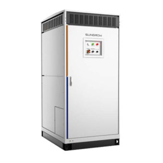
Product Description Product Introduction The PCS is tailored for medium and large-scale energy storage stations, with a container designed in line with outdoor standards. Equipped with the converter unit, power distribution cabinet, communication device, etc., the PCS can convert DC power from energy storage batteries into AC power that meets the in-grid requirements, and directly feed the AC power into the medium-voltage grid. - Page 23 User Manual 3 Product Description Description Item Name Nameplate Identify the PCS from the nameplate Hot air exits through this vent Air outlet window Maintenance port To install and maintain devices The AC switch is located inside the PCS and only used to start/stop the PCS. SUN- GROW shall hold no liability for damage caused by inappropriate operations.
- Page 24 3 Product Description User Manual Emergency Stop Button Press the emergency stop button in emergencies or fault condition to shut down the PCS immediately. Electrical shock hazards! • Even if the emergency stop button is pressed, voltage may also exist in the AC and DC connection terminals inside the PCS.
-
Page 25: Mechanical Data
User Manual 3 Product Description Rain Cover The product shown below is the version without a rain cover. Please refer to the actual product received. The rain cover is currently applied to UD series PCS. 3.2.2 Mechanical Data Dimensions... -
Page 26: Ventilation Design
3 Product Description User Manual Height Depth Width 1080mm 2400mm 1400mm 3.2.3 Ventilation Design Cooling air comes into the PCS from the top air vent and hot air goes out of the PCS from the bottom air vent. It’s shown in the figure below. figure 3-2 Ventilation diagram •... - Page 27 User Manual 3 Product Description figure 3-3 Single branch version(SC1200UD-US/SC1375UD-US/SC1575UD-US/SC1725UD-US/ SC2000UD-US/SC2500UD-US)
- Page 28 3 Product Description User Manual figure 3-4 Multi-branch version(SC1200UD-US/SC1375UD-US/SC1575UD-US/SC1725UD-US) figure 3-5 Multi-branch version(SC2000UD-US/SC2500UD-US) *The above figures are for reference only, please refer to the actual product received. UD series PCS support a single PV input and multiple PV inputs. Please refer to the actual needs.
-
Page 29: Overview Of Operation Switches
User Manual 3 Product Description Item Name Mark Disconnect the switches before Maintenance switch maintenance. AC circuit breaker Connect/disconnect the AC side of the PCS. DC load switch Connect/disconnect the DC side of the PCS. L1, L2, L3 AC connection area Fuse Including positive and negative terminals. -
Page 30: Operations On Dc Load Switch&Ac Circuit Breaker
3 Product Description User Manual figure 3-6 External Power Supply Interface Disconnect Q3 and close Q2 for external power supply. 3.3.3 Operations on DC Load Switch&AC Circuit Breaker • Never manually close the DC load switch&AC circuit breaker. • Before powering on the DC side, ensure that the DC load switch&AC circuit breaker are disconnected. - Page 31 User Manual 3 Product Description figure 3-7 DC load switch&AC circuit breaker Description Item Name When the load switch does not store energy, manually Manual energy storage store energy through this handle. handle Status indicator (energy "CHARGED" indicates energy storage; and "DIS- storage) CHARGE"...
-
Page 32: Cable Inlet/Outlet Design
3 Product Description User Manual If it is already in a "CHARGED" state, there is no need for manual operation. Never manually connect the AC circuit breaker when the AC side carries voltage. Never manually connect the DC load switch when the DC side carries voltage. Avoid faults and accidents caused by DC side voltage impact. - Page 33 User Manual 3 Product Description figure 3-8 Cable entries on the bottom of the PCS The AC/DC cover plate cannot be discarded during cable wiring and must be rein- stalled to ensure protection for internal equipment.
-
Page 34: Delivery
Delivery Scope of Delivery Materials described in this section should be included in the crate. Quantity Item Name Note Including keys and other accessories User Manual Warranty Card Product Test Report Quality Certificate Identifying PCS Identify the PCS from its nameplate, which is attached to the side cover plate of the PCS, shown as A in the figure below. -
Page 35: Checking For Transport Damage
Checking the Package Check whether the outer package is damaged during transport. If any damage is found, con- tact the shipping company or SUNGROW immediately. Checking the PCS After unpacking, check the following items for any possible damages: •... -
Page 36: Storage
4 Delivery User Manual If any damage is detected, contact the shipping company or SUNGROW immediately. A rel- evant photo is preferred. We will provide you with the fast and best service. Install and commission the PCS only when it is technically faultless! Before instal- lation, make sure that: •... -
Page 37: Mechanical Mounting
Never place any flammable substance inside or around the installation place. • The rated power operating temperature of SC1200UD-US/SC1375UD-US/SC1575UD- US/SC1725UD-US/SC2000UD-US is recommended to be ranged between -35℃ and + 45℃, and the rated power operating temperature of SC2500UD-US is recommended to be ranged between -35℃... -
Page 38: Clearance Space
5 Mechanical Mounting User Manual Holes need to be designed on the foundation, and the dimensions should be consistent with those of the location holes on the PCS bottom, so that the PCS can be firmly attached to the foundation. Eight slotted holes of 15mm×15mm are designed on the bottom of the PCS, as shown in the figure below. -
Page 39: Ventilation Requirements
User Manual 5 Mechanical Mounting figure 5-2 Clearance space around a single PCS Multiple PCSs In case of multiple PCSs, the clearances should meet the following requirements: figure 5-3 Clearance space around multiple PCS 5.2.3 Ventilation Requirements The heat generated (hot air exhausted) by the PCS must be dissipated out of the electrical control room as soon as possible, to ensure safe operation and high feed-in power. -
Page 40: Cable Trench
5 Mechanical Mounting User Manual • When the PCS is exposed to sunlight, interior temperature rises rapidly, which impairs charging and discharge. Install an awning or other shading equipment or install the PCS in a shade. • Considering the local wind direction when designing the air outlet orientation. 5.2.4 Cable Trench The external cables can route into or out of the cabinet through the bottom of the PCS. -
Page 41: Wiring Requirements
User Manual 5 Mechanical Mounting Wiring Requirements Cables in the PCS can be classified into power cables, control cables and communication cables. Power cables and communication cables should be laid in different cable supports with a distance greater than 200mm. Avoid long parallel runs of the two kinds of cables to decrease electromagnetic interference. -
Page 42: Transport And Shipping
5 Mechanical Mounting User Manual Transport and Shipping 5.5.1 Attentions • The PCS should be transported and installed as an integrated unit. Failure caused by unauthorized disassembly is not covered by warranty. • Transport the PCS strictly following the description in this chapter. •... - Page 43 User Manual 5 Mechanical Mounting Unpack the PCS only when it is to be installed. The PCS that has been unpacked can be transported by forklift, crane, slide rails, etc. Additional traction may be required if the PCS needs to be transported on slopes. Slow down and be careful when moving the PCS on a slope to prevent it from slid- ing down the forks and hitting the forklift.
- Page 44 5 Mechanical Mounting User Manual The base covers of the PCS had been removed and packed into the cabinet be- fore packaging. • Lifting and transportation *The figure above is indicative only. The PCS can be lifted and transported by crane. Remove all wooden sealing boards around the cabinet before hoisting.
- Page 45 User Manual 5 Mechanical Mounting figure 5-6 Move the PCS by a crane *The figure above is indicative only. table 5-2 Composition of Load-lifting Attachment Name Specifications Description Sling 1 Sling 1 is attached to the hook. A Not included in the scope of supply single sling shall be no shorter than 4000 mm, and shall at least bear 9000 KG.
-
Page 46: Field Installation
Hoist the auxiliary hoisting beam on the top after tightening the screws! The auxiliary hoisting beam on the top of the equipment is included in the delivery accessories. If the customer provides hoisting tools, please contact SUNGROW in advance. Field Installation •... -
Page 47: Unpacking The Pcs
User Manual 5 Mechanical Mounting 5.6.1 Unpacking the PCS Since the PCS package is heavy, please make sure at least two persons work to- gether to unpack the PCS. Proceed as follows to unpack the PCS from the shipping crate: step 1 Remove the crate’s wooden top plank. -
Page 48: Fixing The Pcs
5 Mechanical Mounting User Manual 5.6.3 Fixing the PCS Proceed as follows to fix the PCS: step 1 Move the PCS to the final installation place using proper tools; step 2 Fix the PCS to the steel channel or ground by M12 bolts; step 3 Install the front and rear panels of PCS base to finish the PCS fixing. -
Page 49: Electrical Connection
Electrical Connection Safety Instructions 6.1.1 General Rules High voltage! Electrical shock! • Do not touch the live component! • Ensure that both the AC and DC sides are voltage-free before installation. • Never put flammable materials in the vicinity of the PCS. •... -
Page 50: Five Safety Rules
The installation and design of the PCS must comply with national and local standards and regulations. • SUNGROW should hold no liability for the PCS or system fault caused by igno- rance of the description in this manual. Select optical fibers as the external communication cable to lower signal interference. -
Page 51: Installation Tools
User Manual 6 Electrical Connection • Disconnect all external connections and the PCS internal power supply • Avoid any accidental re-connections. • Verify that no voltage or current is present with appropriate measuring devices. • Grounding whenever necessary. • Cover possible live parts to avoid accidental contact. Installation Tools Prepare the following tools before installation: •... -
Page 52: Copper Wire Connection
6 Electrical Connection User Manual Clean the terminals before cable connection. Do not touch the terminal after cleaning. Spare parts required for power cables connection like the screws are within the scope of de- livery. Please respect the description in this chapter during connection. 6.3.1 Copper Wire Connection If copper wires are used, connect the spare parts as described below: figure 6-1 Copper wire terminal connection sequence of single-hole cable connection... -
Page 53: Preparation Before Electrical Connections
User Manual 6 Electrical Connection figure 6-4 Copper-aluminum composite terminal of double-hole cable connection Select a cable connection method based on actual needs. When the busbar has several connection terminals, an intact copper-aluminum composite sheet is required as shown in the following figure. figure 6-5 Copper-aluminum composite sheet connection sequence *The figure above is indicative only. -
Page 54: Removing The Protective Mesh
6 Electrical Connection User Manual Unlock all six door locks with keys to open the cabinet door. Be sure to secure all door locks reliably when closing the cabinet door to avoid ac- cidents caused by poor protection. 6.4.2 Removing the Protective Mesh The PCS is equipped with a protective mesh inside to maintain safe operation. -
Page 55: During Connection
User Manual 6 Electrical Connection 6.4.4 During Connection • Make sure the polarities of the DC cables and the phase sequence of the AC ca- bles are correct before connection. • Do not pull the cables hard during electrical connection. •... - Page 56 6 Electrical Connection User Manual table 6-1 Cable Specification of Single-branch Version Connec- Specifications Requ. Note Cable tion holes Eight wir- Alumi- ing inputs, num/ each with Copper two holes The cross-sectional area of cables arranged the positive and negative in- can be DC input up and...
- Page 57 User Manual 6 Electrical Connection table 6-2 Cable Specification of Multi-branch Version Connec- Specifications Requ. Cable tion Note holes Alumi- num/ Copper Each The cross-sectional area of cables branch the positive and negative in- can be DC input has two Φ13 put cables is 240 mm (or 600...
-
Page 58: Dc Connection
6 Electrical Connection User Manual • Ensure that the positive and negative DC cables are laid at a safe distance to avoid crossing and to reduce the possibility of short circuits. • The positive and negative DC voltage must be strictly tested to ensure that the voltage range meets the requirements of the product and the positive and nega- tive polarity are connected correctly. - Page 59 User Manual 6 Electrical Connection figure 6-6 DC side terminals of single branch version (SC1200UD-US/SC1375UD-US/SC1575UD-US/ SC1725UD-US/SC2000UD-US/SC2500UD-US) For multi-branch PCS, the number of branches varies from model to model. SC1200_1375_ 1575_1725UD-US supports up to 12 branches and SC2000_2500UD-US supports up to 10 branches, as shown in the figure below.
- Page 60 6 Electrical Connection User Manual After the wiring work, the bottom cover must be reinstalled. step 4 Lead the cable through the gland at the bottom of the PCS. step 5 Strip off the insulation cover of the cable end with a stripped length of 5mm longer than the depth of the cable lug.
- Page 61 User Manual 6 Electrical Connection figure 6-9 Connection sequence Copper bus Cable lug Bolt Disc spring Flat washer washer • Respect all the safety instructions listed by the device manufacturer. Incorrect connection sequence may cause fire. Please pay maximum attention to the con- nection sequence.
-
Page 62: Ac Connection
6 Electrical Connection User Manual step 11 Reassemble the bottom sealing plate. - - End AC Connection 6.7.1 Safety Instructions Incorrect AC connection may affect the normal operation of or cause damages to the PCS. Electric shock hazards upon touching the live components! •... -
Page 63: Ac Cable Connection
User Manual 6 Electrical Connection figure 6-10 AC cable layout inside the cable trench Description Requirement Item Cable diameter B≥2A Distance between cable groups 6.7.3 AC Cable Connection PCS AC side connection terminals are shown in the following figure: figure 6-11 AC side connection terminals PCS AC output is fed to the grid via the medium-voltage transformer. - Page 64 6 Electrical Connection User Manual A tubing with a length of 2cm longer than the cable lug is recommended; Insert the heat-shrinkable tubing into the cable lug; Shrink the tubing with hot air blower. Cable protectors are advisable in the cable crosses if the multi-core cables are used.
- Page 65 User Manual 6 Electrical Connection figure 6-13 Connection sequence when two cable lugs are used Copper Bus Cable lug Bolt Disc spring Flat washer washer • Incorrect AC connection sequence may cause fire. Please notice the cable con- nection sequence. •...
-
Page 66: Ground Connection
6 Electrical Connection User Manual Ground Connection Ground cable should be grounded properly. Otherwise, • Electrical hazards may follow if a fault occurs. • The device may be damaged during lightning. • The device may not operate normally. • Observe codes and regulations of the country/region where the project is lo- cated to perform ground connections. -
Page 67: Connection Of Ground Copper Bar
User Manual 6 Electrical Connection figure 6-14 Positions of the external grounding points The on-site PE cable shall be connected to the external grounding terminal of the PCS cabinet. It is strictly prohibited to connect it to the grounding bar inside the PCS cabinet! The external grounding terminal of the PCS cabinet is covered with a protective sticker, which must be torn off before on-site ground connection. -
Page 68: Ground Of The Shielded Layer Of Communication Cable
6 Electrical Connection User Manual If different cabinets are not connected by bolts, adopt either of the following two methods to ensure that they are equipotential. • Fix the single-core yellow-green cable of at least 25mm to the frame of the PCS enclo- sure with cable connection plate and bolt. -
Page 69: Inspection After Cable Connection
User Manual 6 Electrical Connection 6.10 Inspection After Cable Connection After all electrical connections are completed, the wiring should be thoroughly and carefully checked. The PCS is equipped with a pressure relief device, which is temporarily fixed with screws to prevent its accidental falling off during transportation. -
Page 70: Installation Checklist
6 Electrical Connection User Manual - - End 6.11 Installation Checklist Check the mechanical and electrical installation of the PCS after the above-mentioned oper- ations. Go through the checklist below with the aid of another person. Make records during checking. Make improvements once any unconformity is found. Mechanical Installation □... - Page 71 User Manual 6 Electrical Connection Others □ Tighten all unused cables with insulation belts □ No tools, parts, conductive dust from drilling, or other foreign objects are left in- side the cabinet □ No condensing or icing inside the cabinet...
-
Page 72: Commissioning
Commissioning Commissioning Requirements Before starting PCS for the first time, thoroughly inspect the PCS for correct and secure installation. • Make sure all cables are connected correctly and all bolts are screwed securely. • Make sure AC circuit breaker and DC load switch are in the disconnected state. •... -
Page 73: Checking The Pcs
User Manual 7 Commissioning 7.2.2 Checking the PCS Check the PCS before powering on it: • Ensure the AC and DC switches are disconnected. • Ensure that the maintenance switch (Q1) and AC switch (Q3) are closed. • Ensure the START/STOP switch is at the START position and can work normally. •... -
Page 74: Preparation Before Starting
7 Commissioning User Manual • Measure accurately the AC grid side frequency. The measured data should not exceed the grid permissible frequency range of the PCS. • Measure the voltage THD of each phase if necessary. PCS may not operate if the THD is serious. -
Page 75: Completing Commissioning
User Manual 7 Commissioning step 4 The POWER indicator on the front panel will light up if the PCS control circuit is closed nor- mally,and the Web page is on. step 5 Running status on the Web pageis "Stop". Refer to the section “Operation Parameters”in this manual, and select an operation mode and running parameters on the running parame- ter interface according to demands. -
Page 76: On-Site Commissioning Of Two-Stage Pcs
SC2500UD and its parallel model SC5000UD is about 91 V, and the difference of the other models is about 180 V if the two stage energy storage mode is enabled. - - End Please contact SUNGROW if the IP address of the PCS and the BSC needs to be modified on site. -
Page 77: Pcs Start/Stop
PCS Start/Stop Starting the PCS 8.1.1 Inspection before PCS Start After completing maintenance or troubleshooting, start the PCS. Ensure that all the following items meet requirements before starting the devices. • All connections are done by strictly following the installation manual and circuit diagram. •... -
Page 78: Stopping The Pcs
8 PCS Start/Stop User Manual step 2 Confirm that the AC and DC side cables are well connected, and then close the switches of the front and rear devices of the PCS. step 3 Measure the voltage of the to-be-connected battery to ensure that it falls within the allowable range. -
Page 79: Stop In Case Of Fault Or Emergency
User Manual 8 PCS Start/Stop During normal operation of the PCS, do not directly disconnect the DC load switch. Otherwise damage to the switch or even the PCS caused by electric arcs may occur. 8.2.2 Stop in Case of Fault or Emergency In case of emergency or fault, proceed as follows to stop the PCS: Press the emergency stop button or rotate the start/stop button to the "STOP"... -
Page 80: Operating Mode
Operating Mode Basic Functions The PCS is equipped with the following functions: Grid-connected operation The PCS is designed with perfect grid—connected operation function and can flexibly adapt to different batteries to control charging and discharging. Charging/discharging mode and charging/discharging instruction are set through the PC or on the user interface. The specific operation modes are as follows: Grid—connected constant power (AC), grid—connected constant power (DC), grid—con- nected constant voltage, and grid—connected constant current are set according to dispatch... - Page 81 User Manual 9 Operating Mode boost transformer of the plant. The entire plant will be in a state of no electricity after it is dis- connected from the grid if the grid suffers a major accident. Black start is defined as the process in which the major power generation unit in the plant reboots out of no electricity and is connected to the grid or establishes a grid.
- Page 82 9 Operating Mode User Manual Desciptions Range Parameter Default PdecMax Maximum derating power on P(f) curve 100% 0%~110% PIncMax Maximum rising power on P(f) curve 100% 0%~110% P-U Curve figure 9-2 P(U) curve table 9-2 Description of P-U curve Parameters Desciptions Range Parameter...
- Page 83 User Manual 9 Operating Mode Q(U) Mode figure 9-3 Q(U) curve table 9-3 Q(U) Mode Parameters Descriptions Desciptions Range Parameter Default Minimum Grid voltage at P1 on Q(U) curve 80%~90% Voltage Grid voltage at P2 on Q(U) curve 95%~100% Grid voltage at P3 on Q(U) curve 105% 100% ~105%...
-
Page 84: Working State Description
9 Operating Mode User Manual Q(P) Mode figure 9-4 Q(P) curve table 9-4 Q(P) Mode Parameters Descriptions Desciptions Range Parameter Default Q(P)Curve P1 Output power (%) at P1 on Q(P) curve 100% 50%~100% Q(P)Curve P2 Output power (%) at P2 on Q(P) curve 0%~50% Q(P)Curve P3 Output power (%) at P3 on Q(P) curve... -
Page 85: State Switching
User Manual 9 Operating Mode Press to shut down When no instruction operation or scheduling is performed on the PCS, the system is in the stop state after initial stop. When no fault, alarm, or other abnormal status exists, the PCS receives the operation in- struction or scheduling from the WEB SERVER interface or PC in the stop mode. -
Page 86: Operating Mode
9 Operating Mode User Manual press to shut down state. In this state, the PCS blocks IGBT pulse and disconnect the AC and DC switches. In the standby state, the PCS blocks IGBT pulse, but closes AC and DC switches, and the PCS is in hot standby state. -
Page 87: Mode Switching
User Manual 9 Operating Mode In the grid—connected state, the PCS automatically detects grid voltage signals, and per- forms operations synchronous with the grid. The grid—connected active power and reactive power can be adjusted via active power setting and reactive setting respectively. In the off-grid state, the PCS exports AC voltage and create a voltage source within a specif- ic frequency range, so as to supply power for the load. -
Page 88: Web Operation
10 Web Operation 10.1 Running Environment Requirements Item Parameter Browser Chrome 65 above Min. resolution 1024 x 768 10.2 Login Steps Connect the SCU to the PC network card. Configure the IP of the PC to a network segment the same as that of the ETH2 port. The IP of ETH2 port is 192.168.13.127 by default, and therefore, the IP of the PC can be set to 192.168.13.X, and the subnet mask is 255.255.255.0. - Page 89 User Manual 10 Web Operation Description Item Name Navigation Display main function modules of the Web. menus Function dis- Display the current interface. play area Display the current alarm level and alarm number. Users can Alarm icon click the icons to enter the corresponding alarm interface. Help Display the basic configuration steps of the SCU.
-
Page 90: Web Menu
Refer to the chapter “[System Time]”. step 4 Automatically search the device. Devices that can be automatically searched, such as SUNGROW power conversion system, can be added via the auto search function with addresses allocated automatically. Refer to the chapter “[Device List]”. -
Page 91: Overview
User Manual 10 Web Operation - - End 10.6 Overview 10.6.1 General Information Click [Overview]→ [General Information] to enter the corresponding interface. Shotcut Menu Device Setup: devices can be automatically searched and added. Click the menu to add, de- lete, modify, and view the device. Perform auto search to search devices meet conditions and to automatically allocate addresses. -
Page 92: Real-Time Status
10 Web Operation User Manual System Maintenance: perform operations such as system upgrade, system rebooting, and restoring factory default. Refer to the chapter “[System Maintenance]”. Device Instruction: perform operations, such as start, stop, and standby. Power flow View power flow of the PCS. Data Index View information such as Daily Discharge, Cumulative Discharge, Daily Charge, Cumulative Charge, Real-time Active Power, Real-time Reactive Power, Offline Device, and Online... -
Page 93: Operation Parameters
User Manual 10 Web Operation - - End 10.7.3 Operation Parameters It is recommended that the input voltage of the DC battery of two PCS units sharing a transformer in the MV system be controlled within 100V, and excessive voltage difference will affect the performance of the parallel system. -
Page 94: Device Instruction
10 Web Operation User Manual step 2 Set the start time and end time, and the start time should be earlier than the end time. step 3 Set the power, which can be set to a value ranging from -110 to 110. step 4 Select the desired setting, and click “[Setting]”... -
Page 95: Firmware Update
3 Click “[Confirm]” on the pop-up window. - - End 10.8.2 Firmware Update Click “[Firmware Update]” to upgrade the firmware of SUNGROW PCS connected to the SCU. step 1 Click “[Device]→[Firmware Update]” to enter the corresponding interface. step 2 Click “[Select a Firmware File]”. Select an upgrading file, and import it to the system, to match the corresponding PCS. -
Page 96: History Data
10 Web Operation User Manual - - End 10.9 History Data 10.9.1 Operation Log step 1 Click “[History Data]→[Operation log]” to enter the corresponding interface. step 2 On this interface, users can view history information. - - End 10.9.2 Historical Status step 1 Click [History Data]→[Fault History] to enter the corresponding interface. -
Page 97: System Time
User Manual 10 Web Operation step 3 Click “Upgrade” on the pop-up version information window. The system enters upgrading state. - - End The upgrade file must be the ".scu" file. If there is no new measuring point function, there is no need to re-select the tem- plate and default configuration for the template upgrade in the scu software;... -
Page 98: Transfer Configuration
10 Web Operation User Manual When the clock source is set to "NTP", time of all devices can be synchronized. Click the "Time zone" drop-down-list to select the local time zone. Fill in "Domain", set the time in- terval, and click [Save], so that the SCU time is synchronized with server time. Set the system time when using the SCU for the first time. -
Page 99: Template Management
User Manual 10 Web Operation step 3 Click “[Forwarding service]”, to view device name, local port, and forwarding address. step 4 Click “[Network Port]”, to set peer-end IP. - - End 10.10.4 Template Management step 1 Click “[System]→[Template Management]” to enter the corresponding interface. step 2 Click “[Generate template]”, and fill in the template name in the pop-up window. -
Page 100: Kernel Management
10 Web Operation User Manual Network Port Default IP ETH1 192.168.0.100 ETH2 192.168.13.127 step 3 If "Automatically obtain IP settings (DHCP)" is set to [ ], fill in the information such as the IP address, subnet mask, and default gateway, and click the button [ ] to save the operation. -
Page 101: About
User Manual 10 Web Operation 10.11 About Click [About], to enter the corresponding interface. Users can view firmware information of the PCS on this interface. -
Page 102: Pcs Functions
SRD(s), and returns to the pre- disturbance current level or percentage as defined in the requirements document within the time specified in the local standards or regulations. SUNGROW’s PCS meets the above mentioned requirements. -
Page 103: Temperature Derating
User Manual 11 PCS Functions 11.2 Temperature Derating 11.2.1 Discharge Temperature Derating figure 11-2 Discharge temperature derating curve of SC1200UD-US/SC1375UD-US/SC1575UD-US/ SC1725UD-US/SC2000UD-US Ambient temp. T PCS operation situation T<-35℃ The PCS starts with the aid of auxiliary heater -35℃<T≤45℃ Operate for a long time at 100% of the overload condition 45℃<T≤50℃... -
Page 104: Charge Temperature Derating
11 PCS Functions User Manual 11.2.2 Charge Temperature Derating figure 11-4 Charge temperature derating curve of SC1200UD-US/SC1375UD-US/SC1575UD-US/ SC1725UD-US/SC2000UD-US Ambient temp. T PCS operation situation T<-35℃ The PCS starts with the aid of auxiliary heater -35℃<T≤45℃ Operate for a long time at 100% of the overload condition 45℃<T≤50℃... -
Page 105: Altitude Derating
User Manual 11 PCS Functions 11.3 Altitude Derating 11.3.1 Discharge Altitude Derating When the PCS working altitude is below 2000m, the PCS can operate at 100% of the nor- mal. The PCS should derate its output power according to the curve shown below when the PCS working altitude is above 2500m. - Page 106 11 PCS Functions User Manual Grid over-/under-voltage protection When the grid voltage exceeds the allowable range, PCS will stop operating, send warning signal and display the fault type on the Web touch screen. The PCS can detect the anomaly and respond quickly. Grid over-/under-frequency protection When the grid frequency exceeds the allowable range, PCS will stop operating, send warn- ing signal and display the fault type on the Web touch screen.
-
Page 107: Remote Control Function
User Manual 11 PCS Functions AC voltage unbalance When the three-phase AC voltage differences detected exceed the allowable range, the PCS will stop operating, send warning signal and display the fault type on the Web. The PCS can detect the anomaly and respond quickly. Transformer over-temperature The PCS transformer is equipped with high-precision thermal sensor to monitor the temper- ature of the module. - Page 108 11 PCS Functions User Manual A:Communication interfaces The figure above is indicative only, and actual product may differ. Remote Emergency Stop Remote emergency stop terminals XB10-5 and XB10-11 are reserved on the host PCS. By connecting them, the PCS can be stopped. B:Remote emergency stop terminals The figure above is indicative only, and actual product may differ.
- Page 109 User Manual 11 PCS Functions • It is forbidden to carry out the wiring with live electricity. Wiring should be carried out when the machine is not powered on, and 17AWG cables are recommended. • The miniature circuit breaker (recommended voltage and current are 30V/1A) is required to control the connection of remote emergency stop terminals, so as to control the operation of the PCS.
-
Page 110: Cyber Security Protocol
Users can click "Forgot Password" on the login page to reset their password. Please contact SUNGROW in case of any problems. 12.2 Port Protection and Isolation Ensure that the PCS is installed such that the network zone has ingress protection and minimized port exposure. - Page 111 User Manual 12 Cyber Security Protocol Ensure that all RS-485 data cables are inspected periodically for damage, wear and tear.
-
Page 112: Cybersecurity Best Practice
13 Cybersecurity Best Practice It’s important to locate the PCS in a secure network zone (e.g., SCADA network or PCN), that is blocked from direct communication with the Internet and/or Corporate IT networks by network security devices (e.g., firewalls). This network isolation concept is a best practice recommendation based on the Purdue Reference Model (PRM), an industry leading Industrial Control System (ICS) cybersecurity model adopted by standards and frameworks such as the ISA 62443,... -
Page 113: Routine Maintenance
14 Routine Maintenance Due to the effect of ambient temperature, humidity, dust and vibration, the inner components of the PCS will be aging and worn out. To ensure the system safety and maintain the effi- ciency of the PCS, it is necessary to carry out routine and periodic maintenance. All methods or operations to keep the PCS in good working condition are concluded as PCS maintenance. -
Page 114: Maintenance And Interval
14 Routine Maintenance User Manual • Necessary ground and short circuit connections. • Cover the adjacent electrical components with insulation cloth during operation. 14.2 Maintenance and Interval Recommended routine maintenance work and maintenance interval are shown in the follow- ing table. Item Method Interval... - Page 115 User Manual 14 Routine Maintenance Item Method Interval Six months • Check whether the power cable connections after com- are loose. Retighten them with the torque speci- missioning fied in the manual if necessary; for the first Power circuit • Check if the power cables and control cables, time and connection...
-
Page 116: Replacing Electrical Components
The electrical components inside the PCS must be replaced by the same compo- nents from the same manufacturer and with the same model number. The model number can be acquired from the marking of the PCS or the component itself. If otherwise, please contact SUNGROW. - Page 117 14 Routine Maintenance If you needs to replace the components with products from other manufacturer and with different model number, a prior analysis and confirmation by SUNGROW is needed. Failure to follow this procedure may lead to physical injury or death and void all...
-
Page 118: Troubleshooting
• A picture of the fault if necessary 15.1 Fault Checking If any power output anomaly or charge/discharge anomaly is detected, you may check the following items before contacting SUNGROW. • Open-circuit voltage of the storage battery • State of the emergency stop button •... - Page 119 920us. 3. If the fault is not caused by the foregoing reasons and still exists, please contact SUNGROW. Normally, the machine will reconnect to the grid when the DC voltage returns to normal. If the fault repeatedly occurs (If the busbar 1.
- Page 120 LVRT required 4. If the fault is not caused by the automaticall- duration. In off-grid foregoing reasons and still exists, y cleared mode: Enable the please contact SUNGROW. 30s after AC under-voltage protective function only after shutdown. the output voltage is stable.
- Page 121 3. If the fault is not caused by the LVRT required shutdown. foregoing reasons and still exists, duration. In off-grid please contact SUNGROW. mode: Enable the AC over-voltage function only after the output voltage is stable. The protection is as the same as that of grid connection.
- Page 122 3. If the fault is not caused by the mode: The function only after foregoing reasons and still exists, fault will be the output voltage please contact SUNGROW. automaticall- is stable. The y cleared protection is as the 30s after...
- Page 123 Wait for the PCS to return to normal. an over-current in automaticall- If the fault persists, please contact Module the hardware (- y cleared for SUNGROW to manually power Protection including AC/DC 5 times at down the machine and clear the over-current), or the most. After fault.
- Page 124 Corrective measures condition condition 5. If the fault is not caused by the foregoing reasons and still exists, please contact SUNGROW. Generally, the machine will reconnect to the grid when the internal temperature returns to normal. If the fault repeatedly occurs: 1.
- Page 125 5s. protection parameter settings. value. 4. If the fault is not caused by the foregoing reasons and still exists, please contact SUNGROW. 1. Three-phase AC output is 1.25 times larger than the rated current. 2. Or the load is 1.3...
- Page 126 10s 2. If the fault is not caused by the without other foregoing reasons and still exists, 3. The faults. please contact SUNGROW. communication is abnormal, and the Tigbt is greater than 93 for 6s in operation mode. 4. The...
- Page 127 73℃ for is lower than if so. 40ms. 65℃ for 4. Check whether the fan is running 200ms. properly. Replace the fan if necessary. 5. If the fault is not caused by the foregoing reasons and still exists, please contact SUNGROW.
- Page 128 3. If the fault is not caused by the foregoing reasons and still exists, please contact SUNGROW. The sampled Battery voltage on the polarity...
- Page 129 If this fault during the startup occurs over Reboot the machine. If the fault AC Switch process, or the five times, it persists, please contact SUNGROW. Fault switch node fails to cannot be cleared open during the shutdown process. automaticall- 1.
- Page 130 IGBT feedback IGBT node signal is feedback abnormal (drive Reboot the machine. If the fault Drive Board node signal power undervoltage, persists, please contact SUNGROW. Fault returns to module conduction normal. through, etc.). The Bus voltage difference between The fault is...
-
Page 131: Appendix
16 Appendix 16.1 Technical Data table 16-1 SC1200UD-US&SC1375UD-US Parameter SC1200UD-US SC1375UD-US DC side parameter Max. DC voltage 1500 V Min. DC voltage 700 V 800 V Working voltage range 700 – 1500 V 800 – 1500 V Max. DC current 1760A No. - Page 132 16 Appendix User Manual Parameter SC1200UD-US SC1375UD-US AC voltage Distortion < 3 % (Linear load) DC voltage component < 0.5 % Un (Linear balance load) Unbalance load Capacity 100% Power factor at nominal power / Ad- 60 Hz / 55 – 65 Hz...
- Page 133 User Manual 16 Appendix Parameter SC1200UD-US SC1375UD-US UL1741, UL1741 SA, IEEE 1547, Rule 21, HECO Compliance 14H, CSA C22.2 No.107.1-01 L/HVRT,L/HFRT, active & reactive power control Grid support and power ramp rate control, Volt-var, Volt-watt, Frequency-watt table 16-2 SC1575UD-US&SC1725UD-US Parameter...
- Page 134 16 Appendix User Manual Parameter SC1575UD-US SC1725UD-US AC voltage range 554 – 693V 607 – 759V AC voltage Distortion < 3 % (Linear load) DC voltage component < 0.5 % Un (Linear balance load) Unbalance load Capacity 100% Power factor at nominal power / Ad- 60 Hz / 55 –...
- Page 135 User Manual 16 Appendix Parameter SC1575UD-US SC1725UD-US UL1741, UL1741 SA, IEEE 1547, Rule 21, HECO Compliance 14H, CSA C22.2 No.107.1-01 L/HVRT,L/HFRT, active & reactive power control Grid support and power ramp rate control, Volt-var, Volt-watt, Frequency-watt table 16-3 SC2000UD-US&SC2500UD-US Parameter SC2000UD-US SC2500UD-US DC side parameter...
- Page 136 16 Appendix User Manual Parameter SC2000UD-US SC2500UD-US DC voltage component < 0.5 % Un (Linear balance load) Unbalance load Capacity 100% Power factor at nominal power / 60 Hz / 55 – 65 Hz Adjustable power factor Efficiency Max. efficiency / CEC efficiency 99 % / 98.5 % Protection DC input protection...
-
Page 137: Tightening Torques
Please refer to the actual situation! **Secure the cable in proper place to reduce pressure of cable lug. 16.3 Quality Assurance When product faults occur during the warranty period, SUNGROW will provide free service or replace the product with a new one. Evidence During the warranty period, the customer shall provide the product purchase invoice and date. - Page 138 • The customer shall give SUNGROW a reasonable period to repair the faulty device. Exclusion of Liability In the following circumstances, SUNGROW has the right to refuse to honor the quality guarantee: • The free warranty period for the whole machine/components has expired.
- Page 139 Sungrow Power Supply Co., Ltd. www.sungrowpower.com...
Need help?
Do you have a question about the SC1200UD-US and is the answer not in the manual?
Questions and answers