Table of Contents
Advertisement
Quick Links
S S C C 1 1 2 2 0 0 0 0 U U D D - - U U S S / / S S C C 1 1 3 3 7 7 5 5 U U D D - - U U S S / /
S S C C 1 1 5 5 7 7 5 5 U U D D - - U U S S / / S S C C 1 1 7 7 2 2 5 5 U U D D - -
U U S S P P o o w w e e r r C C o o n n v v e e r r s s i i o o n n S S y y s s t t e e m m
( ( P P C C S S ) ) O O p p e e r r a a t t i i o o n n M M a a n n u u a a l l S S C C 1 1 2 2 0 0 0 0 _ _
1 1 3 3 7 7 5 5 _ _ 1 1 5 5 7 7 5 5 _ _ 1 1 7 7 2 2 5 5 U U D D - - U U S S - - O O E E N N - -
V V e e r r 1 1 3 3 - - 2 2 0 0 2 2 1 1 0 0 4 4
SC1200_1375_1575_1725UD-US-OEN-Ver13-202104
SC1200UD-US/SC1375UD-US/
SC1575UD-US/SC1725UD-US
P P o o w w e e r r C C o o n n v v e e r r s s i i o o n n S S y y s s t t e e m m ( ( P P C C S S ) )
O O p p e e r r a a t t i i o o n n M M a a n n u u a a l l
Advertisement
Table of Contents

Related Manuals for Sungrow SC1200UD-US


Summary of Contents for Sungrow SC1200UD-US
- Page 1 V V e e r r 1 1 3 3 - - 2 2 0 0 2 2 1 1 0 0 4 4 SC1200_1375_1575_1725UD-US-OEN-Ver13-202104 SC1200UD-US/SC1375UD-US/ SC1575UD-US/SC1725UD-US P P o o w w e e r r C C o o n n v v e e r r s s i i o o n n S S y y s s t t e e m m ( ( P P C C S S ) )
-
Page 3: Table Of Contents
C C o o n n t t e e n n t t s s 1 About This Manual ..................1 1.1 Validity ......................1 1.2 Brief Introduction..................1 1.3 Target Group....................2 1.4 How to Use This Manual................2 1.5 Symbols Explanation .................. - Page 4 4.2 Starting the PCS ..................16 4.2.1 Inspection before PCS Start .............. 16 4.2.2 Starting the Device ................17 4.3 Stopping the PCS ..................17 4.3.1 Normal Stop ..................18 4.3.2 Stop in Case of Fault or Emergency ..........18 5 Operating Mode ..................
- Page 5 6.9.1 Operation Log................... 40 6.9.2 Historical status ................40 6.9.3 Parameter Log.................. 40 6.9.4 Measuring Point Log................. 40 6.10 System ....................41 6.10.1 System Maintenance ..............41 6.10.2 System Time................... 41 6.10.3 Transfer Configuration ..............42 6.10.4 Template Management..............43 6.10.5 Port Parameter ................
-
Page 7: About This Manual
Introduce the daily maintenance of the PCS and the replacement of certain accessories. Troubleshooting • Introduce the potential faults and troubleshooting of the PCS. Others • Technical data of the PCS, exclusion of liability and the way to contact Sungrow. -
Page 8: Target Group
All rights reserved including the pictures, markings and symbols used. Any reproduction or disclosure, even partially, of the contents of this manual is strictly forbidden without prior written authorization of Sungrow. 1.5 Symbols Explanation This manual contains important safety and operational instructions that must be accurately understood and followed during the installation and maintenance of the equipment. - Page 9 Operation Manual 1 About This Manual NOTE indicates additional information, emphasized contents or tips to help you solve problems or save time. The symbols below may be pasted on the electrical parts of the PCS. Make sure to read the following symbols and fully understand them before installing the equipment. S S y y m m b b o o l l s s E E x x p p l l a a n n a a t t i i o o n n s s Risk of electric shock!
-
Page 10: Safety Instructions
Safety Instructions 2.1 Intended Usage This series of Power Conversion System researched and developed by Sungrow Power Supply Co., Ltd., is a PCS for energy storage system without transformer. It provides an interface for the grid and battery for storage system charging and discharging. Through step up by the external transformer, the PCS AC side can connect to the grid or load. -
Page 11: Important Safety Instructions
Installation and connections other than the contents described in this section • may lead to device damages and void warranty claims from Sungrow. 2.2 Important Safety Instructions This section introduces the safety instructions during installing or commissioning of the PCS. -
Page 12: Manuals
2 Safety Instructions Operation Manual The equipment shall be dried after passing through condensing environment, and it is recommended to dry it under ventilation for at least 24 hours. Before running the equipment, insulation resistance test shall be performed, and then withstand voltage test after the insulation resistance test is passed: When all the tests pass, the running operation can be continued. -
Page 13: Safety Warning Signs
Operation Manual 2 Safety Instructions All safety instructions, warning labels and nameplate on the PCS body must • be clearly visible; Replace the markings once they damaged or unclear. • 2.2.4 Safety Warning Signs Please respect the followings during installation, daily maintenance or troubleshooting of the PCS: An obvious marking should be placed in the PCS switches upstream and •... -
Page 14: Live Line Measurement
2 Safety Instructions Operation Manual 2.2.7 Live Line Measurement High voltages are present in the device. Death resulting from burning and electric shock upon touching the live components of the PCS. During live line measurement, use suitable protective equipment , for example dielectric gloves, and •... -
Page 15: Maintenance And Service
PCS. The actual product you receive may differ. Should you have any specific requirements, please inform us. This manual may not cover all possible situations. Should a specific • problem occur that is not explained in this manual, please contact Sungrow. -
Page 16: Product Description
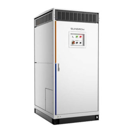
Product Description 3.1 Appearance The external appearance and major components are shown in the following figure. F F i i g g u u r r e e 3 3 - - 1 1 Appearance of the PCS D D e e s s c c r r i i p p t t i i o o n n I I t t e e m m N N a a m m e e Disconnect the PCS from DC side power... - Page 17 3 Product Description The AC switch is located inside the PCS and only used to start/stop the PCS. SUNGROW shall hold no liability for damage caused by inappropriate operations. L L E E D D i i n n d d i i c c a a t t o o r r s s There are three LEDs at the front panel of the PCS: POWER indicates the power is on;...
-
Page 18: Communication Solution
3 Product Description Operation Manual E E m m e e r r g g e e n n c c y y S S t t o o p p B B u u t t t t o o n n PCS will be disconnected the AC and DC side when pressing down the emergency stop button in emergency situation or fault condition. -
Page 19: Ethernet Communication
PCS supports the MODBUS TCP/RTU and 104 protocols. If you have doubts about the communication solution, please contact Sungrow. S S i i n n g g l l e e P P C C S S c c o o m m m m u u n n i i c c a a t t i i o o n n For communication of a single PCS, connect the PCS RJ45 port to PC RJ45 port by a network cable. -
Page 20: Communication With Bms
3 Product Description Operation Manual 3.2.3 Communication with BMS PCS can communicate with battery management system (BMS) to monitor the state of the battery and protect the battery according to the battery state. Communication supports the CAN and RS485 methods. F F i i g g u u r r e e 3 3 - - 5 5 PCS communicates with BMS 3.3 Circuit Diagram PCS realizes rectification and inversion through 3-phase full bridge conversion. -
Page 21: Pcs Start/Stop
PCS Start/Stop 4.1 Operations on DC Load Switch Never manually close the DC load switch. • Before powering on the DC side, ensure that the DC load switch is • disconnected. Under the off-grid condition, ensure that the DC load switch is in the "- •... -
Page 22: Starting The Pcs
4 PCS Start/Stop Operation Manual C C l l o o s s e e t t h h e e s s w w i i t t c c h h Check the charge status before closing the load switch. If the switch is in "DISCHARGE" state, charge it through the manual charging handle until it turns into "CHARGED"... -
Page 23: Starting The Device
Operation Manual 4 PCS Start/Stop 4.2.2 Starting the Device Start the PCS when all the foregoing items meet requirements. The operation steps are as follows: Step 1 Ensure that the AC circuit breaker and the DC load switch of the PCS are disconnected. Step 2 Ensure that cables on the AC &... -
Page 24: Normal Stop
4 PCS Start/Stop Operation Manual 4.3.1 Normal Stop In case of maintenance or troubleshooting, proceed as follows to stop the PCS: Stop the PCS through the stop instruction on the WEB interface. Open the door of the PCS. Ensure that the AC circuit breaker and DC load switch of the PCS are in the "OPEN" state. -
Page 25: Operating Mode
Operating Mode 5.1 Basic Functions The PCS is equipped with the following functions: O O n n - - g g r r i i d d o o p p e e r r a a t t i i o o n n The PCS is designed with perfect on-grid operation function and can flexibly adapt to different batteries to control charging and discharging. -
Page 26: Working State Description
5 Operating Mode Operation Manual mode, the grid-connected reactive power can be controlled by means of reactive power instruction regulation and voltage instruction regulation. 5.2 Working State Description The PCS can be in "key stop", "standby", "running", "emergency stop", or "fault" state. K K e e y y s s t t o o p p When no instruction operation or scheduling is performed on the PCS, the system is in the stop state after initial stop. -
Page 27: State Switching
Operation Manual 5 Operating Mode F F a a u u l l t t When faults occur in the energy storage system, the PCS stops operation and immediately disconnects the DC switch to disconnect the main circuit of the device from the battery, grid, and load. -
Page 28: Vsg Mode
5 Operating Mode Operation Manual 5.4.2 VSG Mode VSG (Virtual Synchronous Generator) control combines the PCS control and synchronous generator control. It borrows the control methods of ordinary pcs and conventional synchronous generator in terms of control policy. From the perspective of external input and output, the PCS is equivalent to a synchronous generator. -
Page 29: Mode Switching
Operation Manual 5 Operating Mode 5.4.3 Mode Switching In the on-grid mode, the PCS can directly switch between charging state and discharging state without a middle transition state. -
Page 30: Web Operation
Web Operation 6.1 Running Environment Requirements I I t t e e m m P P a a r r a a m m e e t t e e r r Browser Chrome65 above Min. resolution 1024x768 6.2 Login Steps Connect the smart unit to the PC network card. -
Page 31: Web Menu
Operation Manual 6 Web Operation I I t t e e - - D D e e s s c c r r i i p p t t i i o o n n N N a a m m e e Navigation Display main function modules of the Web. -
Page 32: Operation Procedure
Refer to the chapter "6.10.2 System Time". Step 4 Automatically search the device. Devices that can be automatically searched, such as SUNGROW string inverter, can be added via the auto search function with addresses allocated automatically. Refer to the chapter "6.8.1 Device List". -
Page 33: Overview
Operation Manual 6 Web Operation 6.6 Overview 6.6.1 General Information Click [Overview] -> [General Information] to enter the corresponding interface. S S h h o o t t c c u u t t M M e e n n u u Device Setup: devices can be automatically searched and added. -
Page 34: Real-Time Status
6 Web Operation Operation Manual D D a a t t e e C C u u r r v v e e View power curve of the PCS. O O p p e e r r a a t t i i n n g g D D a a t t a a View the number of off-grid PCSs and on-grid PCSs, and information such as Device Name, Device Model, Device Status, Work Mode, Active Power, and Charging/ Discharging Status of the PCS. - Page 35 On-grid constant power value (DC) -100.0~100.0 % On-grid constant power value (AC) -100.0~100.0 % On-grid constant current value -1935~1935 A SC1200UD-US: 700.0~1500.0V SC1375UD-US: 800.0~1500.0V On-grid constant voltage value SC1575UD-US: 915.0~1500.0 V SC1725UD-US: 1000.0~1500.0V On-grid constant voltage current limit 0~1935 A...
- Page 36 Operation Manual R R a a n n g g e e P P a a r r a a m m e e t t e e r r SC1200UD-US: 422.0~528.0V SC1375UD-US: 484.0~605.0V Independent inversion voltage SC1575UD-US: 554.0~693.0 V SC1725UD-US: 607.0~759.0V...
- Page 37 Operation Manual 6 Web Operation R R a a n n g g e e P P a a r r a a m m e e t t e e r r Frequency ride through compensation factor 0.0~100.0 % Q(U) voltage rising start point 90.0~110.0 % Q(U) voltage rising end point...
-
Page 38: Protection Parameters
6 Web Operation Operation Manual R R a a n n g g e e P P a a r r a a m m e e t t e e r r BMS communication error duration 5~60 P(U) characteristic activation Enable/Disable P(U) voltage rising start point 100.0~110.0 %... - Page 39 Operation Manual 6 Web Operation R R a a n n g g e e P P a a r r a a m m e e t t e e r r LVRT Voltage 4 5.0~40.0 % LVRT Voltage 5 5.0~40.0 % LVRT T1 40~36000000 ms...
- Page 40 6 Web Operation Operation Manual R R a a n n g g e e P P a a r r a a m m e e t t e e r r Over-voltage Level-1 Trip Time of Power Grid 40~36000000 ms 40~36000000 ms Over-voltage Level-2 Trip Time of Power Grid...
- Page 41 Operation Manual 6 Web Operation R R a a n n g g e e P P a a r r a a m m e e t t e e r r Over-frequency Level-5 Protection Value of 50.00~66.00 Hz Power Grid Fmax-recover 50.10~65.00 Hz...
-
Page 42: System Parameters
Delay for insulation monitoring measuring 30s, 60s, 150s, 180s Insulation monitoring activation Enable/Disable Insulation monitoring switching interval 15min, 30min DC undervoltage setpoint SC1200UD-US:680.0-1550.0 V SC1375UD-US: 780.0-1550.0 V SC1575UD-US:895.0-1550.0 V SC1725UD-US: 980.0-1550.0 V DC overvoltage setpoint SC1200UD-US:680.0-1550.0 V SC1375UD-US: 780.0-1550.0 V SC1575UD-US:895.0-1550.0 V... -
Page 43: Timed Charge And Discharge
Operation Manual 6 Web Operation R R a a n n g g e e P P a a r r a a m m e e t t e e r r Total discharge -3276.7~3276.7 kWh compensation Total charge -3276.7~3276.7 kWh compensation Local/Remote Control... -
Page 44: Device Instruction
6 Web Operation Operation Manual Step 4 Select the desired setting, and click [Setting] in the upper right corner, to save the setting. Step 5 Select the desired setting, click [Configure Synchronization] in the upper right corner, and select a device type in the pop-up window, to synchronize the setting to selected device. -
Page 45: Firmware Update
Step 3 Click [Confirm] on the pop-up window. - - - - E E n n d d 6.8.2 Firmware Update Click [Firmware Update] to upgrade firmware of SUNGROW PCS connected to the Logger. Step 1 Click [Device] -> [Firmware Update] to enter the corresponding interface. -
Page 46: History Data
6 Web Operation Operation Manual Step 1 Click [Device] -> [Fault Recorder] to enter the corresponding interface. Step 2 Click [Read the recorder] and click [Confirm] in the pop-up window, to enable the option. Step 3 Click [Trigger fault recording] and click [Confirm] in the pop-up window, to trigger the option. -
Page 47: System
Operation Manual 6 Web Operation 6.10 System 6.10.1 System Maintenance 6.10.1.1 System Update Users can upgrade the Logger on the Web interface. Step 1 Click [System] -> [System Maintenance] to enter the corresponding interface. Step 2 Click [System Update,] select the upgrade file, and click [Open], to import the file to the system. -
Page 48: Transfer Configuration
6 Web Operation Operation Manual Click the "Time zone" drop-down-list to select the local time zone. Enter "Data" • and "Time", and click [Save], to manually set Logger time. It is recommended to select "User Define" during debugging. When the clock source is set to "NTP", time of all devices can be synchronized. Click the "Time zone"... -
Page 49: Template Management
Operation Manual 6 Web Operation 6.10.3.4 MODBUS Step 1 Click [System] -> [Transfer Configuration] to enter the corresponding interface. Step 2 Click [MODBUS] on the operation bar, to enter the MODBUS interface. Step 3 Click [Forwarding service], to view device name, local port, and forwarding address. Step 4 Click [Network Port], to set peer-end IP. -
Page 50: About
6 Web Operation Operation Manual N N e e t t w w o o r r k k P P o o r r t t D D e e f f a a u u l l t t I I P P ETH1 192.168.0.100 ETH2... -
Page 51: Pcs Functions
PCS Functions 7.1 L/HVRT(UL) The Electric Rule 21, 2015 defines the L/HVRT requirements according to the figure and table below. F F i i g g u u r r e e 7 7 - - 1 1 Low / High voltage withstand requirements For mandatory operation regions, the PCS shall be considered in compliance if it provides an average current greater than or equal to 80% of the pre-disturbance current or other percentage defined in the requirements documents during the ride-... -
Page 52: Temperature Derating
7 PCS Functions Operation Manual Sungrow’s PCS meets the abovementioned requirements. 7.2 Temperature Derating 7.2.1 Discharge Temperature Derating F F i i g g u u r r e e 7 7 - - 2 2 Discharge temperature derating curve A A m m b b i i e e n n t t t t e e m m p p . -
Page 53: Altitude Derating
Operation Manual 7 PCS Functions A A m m b b i i e e n n t t t t e e m m p p . . T T P P C C S S o o p p e e r r a a t t i i o o n n s s i i t t u u a a t t i i o o n n Operate for a long time at 100% of the overload condition 35℃<T≤45℃... -
Page 54: Protection Functions
7 PCS Functions Operation Manual F F i i g g u u r r e e 7 7 - - 5 5 Altitude derating curve 7.4 Protection Functions PCS has perfect protection functions to protect the PCS when input voltage or grid is abnormal until the anomaly is removed and PCS can operate normally. - Page 55 Operation Manual 7 PCS Functions A A C C o o v v e e r r - - c c u u r r r r e e n n t t p p r r o o t t e e c c t t i i o o n n When the battery power exceeds the PCS maximum DC input power, PCS will limit the current to the maximum allowable AC output power.
- Page 56 7 PCS Functions Operation Manual A A D D S S a a m m p p l l i i n n g g f f a a u u l l t t If PCS detects that the sampling channel zero-offset value exceeds the allowable range, PCS will send warning signal and display the fault type on the LCD touch screen.
-
Page 57: Routine Maintenance
Routine Maintenance Due to the effect of ambient temperature, humidity, dust and vibration, the inner components of the PCS will be aging and worn out. To ensure the system safety and maintain the efficiency of the PCS, it is necessary to carry out routine and periodic maintenance. -
Page 58: Maintenance And Interval
8 Routine Maintenance Operation Manual Verify that the PCS interior is discharged completely with a multimeter. • Necessary ground and short circuit connect. • Cover the adjacent electrical components with insulation cloth during operation. • 8.2 Maintenance and Interval Recommended routine maintenance work and maintenance interval are shown in the following table. - Page 59 Operation Manual 8 Routine Maintenance I I t t e e m m M M e e t t h h o o d d I I n n t t e e r r v v a a l l months Check whether the power cable connections •...
-
Page 60: Filter Checking And Cleaning
8 Routine Maintenance Operation Manual I I t t e e m m M M e e t t h h o o d d I I n n t t e e r r v v a a l l Check the emergency stop button and the •... -
Page 61: Replacing Electrical Components
If otherwise, please contact Sungrow. If you needs to replace the components with products from other manufacturer and with different model number, a prior analysis and confirmation by Sungrow is needed. Failure to follow this procedure may lead to physical injury or death and void all... -
Page 62: Troubleshooting
A picture of the fault if necessary • 9.1 Fault Checking If any power output anomaly or charge/discharge anomaly is observed, you may check the following items before contacting Sungrow. Open-circuit voltage of the storage battery • State of the emergency stop button •... - Page 63 Operation Manual 9 Troubleshooting Solution: check and replace the cooling fan; reduce the temperature of the switch room; clean the air duct and widen the air duct. N N o o i i s s e e i i s s T T o o o o L L o o u u d d d d u u r r i i n n g g P P C C S S O O p p e e r r a a t t i i o o n n Possible reason: abnormal operation of the PCS and transformer;...
-
Page 64: Appendix
10 Appendix 10.1 Technical Data S S C C 1 1 2 2 0 0 0 0 U U D D - - S S C C 1 1 3 3 7 7 5 5 U U D D - - S S C C 1 1 5 5 7 7 5 5 U U D D - - S S C C 1 1 7 7 2 2 5 5 U U D D - - P P a a r r a a m m e e t t e e r r... - Page 65 Operation Manual 10 Appendix S S C C 1 1 2 2 0 0 0 0 U U D D - - S S C C 1 1 3 3 7 7 5 5 U U D D - - S S C C 1 1 5 5 7 7 5 5 U U D D - - S S C C 1 1 7 7 2 2 5 5 U U D D - - P P a a r r a a m m e e t t e e r r...
-
Page 66: Exclusion Of Liability
10 Appendix Operation Manual S S C C 1 1 2 2 0 0 0 0 U U D D - - S S C C 1 1 3 3 7 7 5 5 U U D D - - S S C C 1 1 5 5 7 7 5 5 U U D D - - S S C C 1 1 7 7 2 2 5 5 U U D D - - P P a a r r a a m m e e t t e e r r... -
Page 67: Contact Information
Operation Manual 10 Appendix The use of supplied software produced by Sungrow Power Supply Co., Ltd. is subject to the following conditions: Sungrow Power Supply Co., Ltd. assumes no liability for direct or indirect damages • arising from the use of SolarInfo software. This also applies to the provision or non- provision of support activities. - Page 68 M M a a l l a a y y s s i i a a P P h h i i l l i i p p p p i i n n e e s s Sungrow SEA Sungrow Power Supply Co., Ltd Selangor Darul Ehsan Mandaluyong City...
- Page 69 L L u u x x e e m m b b o o u u r r g g ( ( B B e e n n e e l l u u s s ) ) Sungrow Vietnam...
- Page 70 Sungrow Power Supply Co., Ltd. Add: No.1699 Xiyou Rd.,New & High Technology Industrial Development Zone, 230088,Hefei, P. R. China. Web: www.sungrowpower.com E-mail: info@sungrow.cn Tel: +86 551 6532 7834 / 6532 7845 Specifications are subject to changes without advance notice.
Need help?
Do you have a question about the SC1200UD-US and is the answer not in the manual?
Questions and answers