Table of Contents
Advertisement
Quick Links
Advertisement
Table of Contents

Related Manuals for Sungrow PVS-18RM


Summary of Contents for Sungrow PVS-18RM
- Page 1 PVS-18RM PV Reverse Combiner Box User Manual PVS-18RM-UEN-202010...
-
Page 3: Table Of Contents
Table of Contents About This Manual ..............1 Applicability ................1 Brief introduction ............... 1 Intended audience ..............1 Using this manual ..............2 Symbols ..................2 Safety instructions ..............4 Product description ............7 System introduction ..............7 Key features ................7 Appearance and structure ............ - Page 4 Power Up/Down ..............25 Power up .................. 25 Power down ................25 Routine Maintenance ............26 Replacing the fuse ..............26 Replacing the sealing strip ............27 Appendix ................28 Basic parameters ..............28 Warranty .................. 28 Contact information ..............30...
-
Page 5: About This Manual
1 About This Manual 1.1 Applicability This manual is applicable to PVS-18RM PV reverse combiner box which are hereafter referred to as "combiner box" unless otherwise specified. 1.2 Brief introduction This manual is intended for combiner boxes and covers the following: ... -
Page 6: Using This Manual
All contents, pictures, logos and symbols in this manual are the property of SUNGROW. No part of this manual shall be reproduced, in whole or in part, without written authorization by SUNGROW. Descriptions in this manual are subject to changes and may differ from the physical product. - Page 7 User Manual 1 About This Manual "Information" indicates additional information in the manual, which is an emphasis or supplement to the manual and may provide tips for users to better use the product, solve problems or save time. Always pay attention to the hazard warnings on the machine, including: Symbol Description indicates high voltage in the machine.
-
Page 8: Safety Instructions
2 Safety instructions You are advised to read this chapter carefully before installing and using the combiner box. SUNGROW assumes no responsibility or quality assurance for any personal injury or device damage due to failure to observe these safety precautions. - Page 9 User Manual 2 Safety instructions There may be a high voltage electric shock hazard inside the product! Note and observe the warnings on the product. Observe the safety precautions listed in this manual and other related documents of this device. The grounding cable must be well connected to ground, otherwise: ...
- Page 10 2 Safety instructions User Manual When wiring, make sure that the fastening screws of the combiner box terminal are tightened in place. If the copper core of the cable cannot be in full contact with the wiring terminal or pressed tightly, the terminal would be heated and burned after a prolonged period.
-
Page 11: Product Description
The PV power generation system with combiner box is shown in Figure 3-1. Figure 3-1 Composition of the PV grid-connected generation system Table 3-1 Parts list Name PV array PV intelligent combiner box PVS-18RM combiner box Inverter Transformer Public power grid 3.2 Key features Safety and reliability ... -
Page 12: Appearance And Structure
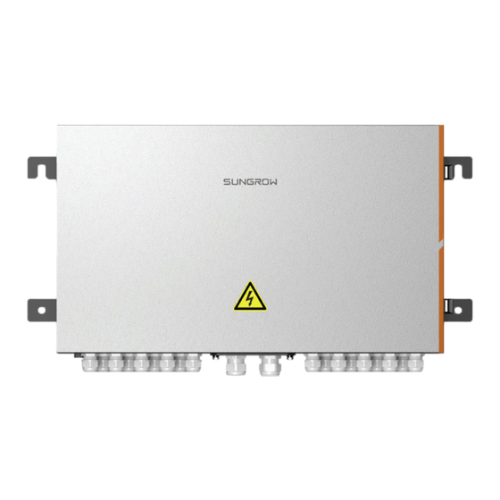
Easy to operate and maintain Light weight, easy to install and handle 3.3 Appearance and structure The appearance of the DC combiner box is shown in the figure below. Figure 3-2 PVS-18RM appearance Name Description Door lock Used to fix the combiner box... -
Page 13: Mechanical Installation
4 Mechanical Installation 4.1 Scope of supply Name Description Quantity Reverse combiner box Related Including certificate, warranty card, documents factory inspection report, etc. Used to open the combiner box door Waterproof Including bottom cover terminal waterproof terminals assembly * Optional 4.2 Dimensions Depth (D) Width (W) -
Page 14: Storage
4 Mechanical Installation User Manual 4.3 Storage The combiner box should be stored under specific environmental conditions when not in use: The combiner box with the outer package should be stored in a ventilated, dry, and clean indoor environment, with desiccant inside. ... -
Page 15: Installation
User Manual 4 Mechanical Installation 4.4 Installation 4.4.1 Installation environment requirements The combiner box features IP65 and is suitable for outdoor or indoor installation. The following requirements should be met: The installation location should fully consider its dimensions and weight (see the parameter chapter for details). - Page 16 4 Mechanical Installation User Manual Multimeter Anti-static wrist Protective gloves Range: strap ≥1000Vdc 880.0 Dust mask Sound insulation Goggles Insulated shoes earplugs Vacuum cleaner Heat-shrink tube Hot air gun Installation tool φ11 impact drill M10 electric M10 screwdriver Wire stripper screwdriver Hydraulic clamp Crimping tool...
-
Page 17: Installation Method
User Manual 4 Mechanical Installation 4.4.3 Installation method When installing the combiner box, fix it to the installation plane through the lugs on its both sides. The hole distance of the lugs on its both sides is shown in the figure below. -
Page 18: Electrical Installation
5 Electrical Installation 5.1 System diagram overview Table 5-1 Device list Description PV module PV intelligent combiner box Reverse combiner box PV grid-connected inverter Transformer Power grid Table 5-2 Cable designation Description Wiring Method Refer to “5.5.1 Input Input cable, connect to PV intelligent combiner box wiring”... -
Page 19: Internal Structure
User Manual 5 Electrical Installation 5.2 Internal structure Taking PVS-18RM for example, the internal structure of the combiner box is shown in the figure below. Description Positive output fuse box and fuse Negative output fuse box and fuse Positive input terminal... -
Page 20: Preparation Before Wiring
5 Electrical Installation User Manual Waterproof terminal model Cable OD Description Model (mm) PGB25* 16~20 Positive input waterproof INPUT DC+ terminal PGB29** 18~25 PGB25* 16~20 Negative input waterproof INPUT DC- terminal PGB29** 18~25 Grounding waterproof PG-16 10~14 terminal Positive output waterproof OUTPUT DC+ terminal MGB24-H2... -
Page 21: Wiring
User Manual 5 Electrical Installation 5.5 Wiring 5.5.1 Input wiring Wiring Area Overview Input wiring hole, as shown in the figure below. INPUT DC+ INPUT DC- Φ11 Φ11 Input the rated current of the copper bar 300A. When selecting the cable specifications, this... - Page 22 5 Electrical Installation User Manual Pass the cable with the wire designation "DC+" through the waterproof Step 2 terminal "INPUT DC+", and reserve an appropriate length margin. Strip the protective layer and insulation layer of the cable to expose the Step 3 copper core of the wire L≈25mm, crimp the cable to an appropriate DT terminal, and insert it into a heat shrink tube.
- Page 23 User Manual 5 Electrical Installation Figure 5-2 Aluminum wire connection diagram Copper Copper aluminum Spring Flat M10 bolt transition terminal cushion washer Install the waterproof terminal assembly to the bottom of the combiner Step 5 box. Wiring scheme 2 Pass the cable with the wire designation "DC+" through the "INPUT Step 1 DC+"...
-
Page 24: Output Wiring
5 Electrical Installation User Manual Figure 5-3 Copper wire connection indication Copper Copper Spring Flat connecting M10 bolt cushion washer terminal For aluminum wire, the fixing method is as shown in the figure below, and the tightening torque is 34~40N.m. Figure 5-4 Aluminum wire connection indication Copper Copper... - Page 25 User Manual 5 Electrical Installation Improper cable connection may cause damage to the PV module, combiner box, and inverter. When wiring, observe the following precautions: Wire according to the wiring drawing. Before wiring, use a multimeter to measure the positive and negative polarity of each channel to ensure that there is no reverse connection.
-
Page 26: Grounding
5 Electrical Installation User Manual Crimping. Insert the cable without the insulation layer into the European Step 4 tubular terminal, and use a special crimping tool to crimp. Connect the cable and tighten it according to as shown in the figure Step 5 below. - Page 27 User Manual 5 Electrical Installation Grounding holes A riveted screw should be installed on the grounding hole inside the combiner box. The riveted screw is M4. The location is as shown in the figure below. It can be installed in the corresponding riveted screw hole according to the actual needs.
- Page 28 5 Electrical Installation User Manual Fix screw, spring washer, flat washer, OT terminal and ground hole to the Step 5 ground point in order. For tightening torques, refer to “Table 5-3 Comparison table of grounding hole and wiring requirements”. Tighten the nut of the waterproof terminal clockwise. Step 6...
-
Page 29: Power Up/Down
6 Power Up/Down 6.1 Power up Close the output pre-switch of the combiner box. Step 1 Use a multimeter to measure the positive and negative polarity of each Step 2 input in the combiner box to ensure that the voltage is basically the same, and there is no reverse polarity. -
Page 30: Routine Maintenance
7 Routine Maintenance The internal devices of the combiner box would be aging and wearing due to the ambient temperature, humidity, dust and vibration,,which may cause potential failures to the combiner box. Only qualified electricians are allowed to perform the maintenance as described in this chapter. -
Page 31: Replacing The Sealing Strip
It is recommended to regularly inspect the internal sealing strip of the combiner box, which is located in the door cover of the combiner box, see "A" shown in the figure. If there is any non-man-made damage, contact SUNGROW immediately to replace the door cover and sealing strip. -
Page 32: Appendix
The warranty period of this product shall be subject to the contract. For products that malfunction during the warranty period, Sungrow Power Supply Co., Ltd. (hereinafter referred to as " SUNGROW ") shall repair or replace it with new products free of charge. - Page 33 If the product is within the warranty period, the customer shall provide the product purchase invoice and date. In addition, the trademark on the product should be legible. Otherwise, SUNGROW has the right to refuse to honor the warranty. Conditions ...
-
Page 34: Contact Information
Brief description of the fault China Australia 400-119-7799 +61 2 9922 1522 service@sungrowpower.com service@sungrowpower.com.au Brazil France +55 11 2366 1957 +33 762899888 service.france@sungrow.co latam.service@sa.sungrowpower.com Germany Greece +30 2106044212 +49 89 324 914 761 service.greece@sungrow.co service.germany@sungrow.co India Italy +9108041201350 +39 3391096413 service@in.sungrowpower.com...
Need help?
Do you have a question about the PVS-18RM and is the answer not in the manual?
Questions and answers