Table of Contents
Advertisement
Available languages
Available languages
Quick Links
MANDO POR CABLE
WIRED CONTROLLER
ECRP86EKD
MANUAL DE
INSTRUCCIONES
Escanee para ver este manual en otros idiomas y actualizaciones:
Scan for manual in other languages and further updates:
OPERATING MANUAL
Manuel dans d'autres langues et mis à jour:
Manual em outras línguas e actualizações:
V.2
Advertisement
Table of Contents

Related Manuals for EAS Electric ECRP86EKD


Summary of Contents for EAS Electric ECRP86EKD
- Page 1 MANDO POR CABLE WIRED CONTROLLER ECRP86EKD MANUAL DE INSTRUCCIONES Escanee para ver este manual en otros idiomas y actualizaciones: Scan for manual in other languages and further updates: OPERATING MANUAL Manuel dans d'autres langues et mis à jour: Manual em outras línguas e actualizações:...
- Page 3 ● Lea atentamente este manual y asegúrese de entender la información que facilita antes de intentar utilizar el producto. ● Conserve el manual para futuras consultas. ● Si otro usuario va a utilizar este producto en el futuro, asegúrese de entregarle también este manual de instrucciones.
- Page 4 Índice de contenidos Instalación ......................1 1. Precauciones de seguridad ................. 1 2. Accesorios ...................... 3 3. Procedimiento de instalación................4 Funcionamiento ....................9 1. Precauciones de seguridad ................9 2. Componentes del mando con cable ............11 3. Iconos en pantalla..................13 4.
- Page 5 Instalación 1. Precauciones de seguridad Antes de instalar el dispositivo, lea atentamente estas Precauciones de Seguridad. En este manual, las precauciones de seguridad se dividen en dos tipos: ADVERTENCIA y ATENCIÓN. Ambos contienen información importante relacionada con la seguridad. Siga las instrucciones siguientes en todo momento.
- Page 6 ● Asegúrese de utilizar únicamente los accesorios y piezas especificados para los trabajos de instalación. Si no se utilizan las piezas especificadas, la unidad podría caerse, sufrir fugas de agua, descargas eléctricas o incendios. ● Instale el mando de control con cable sobre una base que pueda aguantar su peso. Una base poco resistente puede provocar que el mando con cable se caiga y cause lesiones.
- Page 7 2. Accesorios Compruebe que el paquete contiene las piezas siguientes: Tabla 2.1 Nombre Observaciones Aspecto Ctd. Se utiliza para sujetar Tornillo de estrella, el mando por cable a la M4X25mm caja eléctrica. Se utiliza para sujetar Barra de soporte de el mando por cable a la plástico φ5X16mm caja eléctrica.
- Page 8 3. Procedimiento de instalación 3-1 Determine el lugar donde desea instalar el mando con cable Consulte el apartado «1. Precauciones de seguridad» para determinar la zona de instalación. 3-2 Dimensiones externas 20mm 86mm FOLLOW ME 60mm Figura 3.1 Figura 3.2 3-3 Instalación de la cubierta posterior 3-3-1 Introduzca el destornillador de cabeza plana pequeño en la ranura inferior del mando con cable y gírelo en la dirección indicada para poder quitar la cubierta posterior.
- Page 9 Advertencia • Cuando abra la cubierta posterior del mando con cable con el destornillador de cabeza plana, tenga cuidado de no dañar la PCB. • No toque la PCB del mando con cable. 3-3-2 Utilice una herramienta de corte para ajustar la altura de las dos barras de soporte de plástico (accesorio 2) de forma que la longitud estándar de las varillas roscadas de la caja eléctrica coincidan con la superficie de la pared.
- Page 10 3-3-4 Introduzca los cables apantallados instalados en la pared a través del orificio de la cubierta posterior del mando con cable. Sujete la cubierta posterior del mando con cable a la caja eléctrica a través de las barras de soporte. Utilice para ello los tornillos Philips suministrados (accesorio 1).
- Page 11 3-4-2 Cables de comunicación • La comunicación entre la unidad interior y el mando con cable es bidireccional. Los parámetros mostrados en el mando con cable se actualizan en tiempo real de acuerdo con los cambios en los parámetros de la unidad interior. •...
- Page 12 «principal» y el otro el mando «secundario». Consulte el apartado «Ajustes de campo». Por defecto, el mando con cable viene configurado como mando principal. • Este método solo está disponible en los mandos tipo ECRP86EKD. 3.5 Instalación del cuerpo principal del mando con cable Introduzca los cables apantallados instalados en la pared a través del orificio de la...
- Page 13 X1 X2 Figura 3.10 Figura 3.9 Advertencia • Durante la instalación, reserve cierta longitud para los cables apantallados con el fin de facilitar el desmontaje del mando con cable a la hora de llevar a cabo el mantenimiento. Funcionamiento 1. Precauciones de seguridad Este aparato no está...
- Page 14 Significado Señal El incumplimiento de estas instrucciones puede ocasionar Advertencia daños personales. El incumplimiento de estas instrucciones puede producir daños en la Atención propiedad daños personales podrían graves dependiendo de las circunstancias. Advertencia ● No instale el mando con cable usted mismo. Una instalación inadecuada podría ser el origen de posibles descargas eléctricas o incendios.
- Page 15 Atención ● No manipule el mando con cable. El manejo accidental por parte de un niño puede dañar sus funciones corporales y su salud. ● Nunca desmonte al mando con cable. Presionar las piezas interiores puede provocar descargas eléctricas o incendios. Consulte a su distribuidor o contratista autorizado la realización de inspecciones y ajustes internos.
- Page 16 Tabla 4.1 Botón Funciones 1. Modo Selecciona el modo: Auto → Cool→ Heat→ Dry→ Fan Velocidad del ventilador Ajusta la velocidad del ventilador. Swing Ajusta el movimiento de las lamas. Permite cambiar a las funciones disponibles para el modo Función de funcionamiento seleccionado.
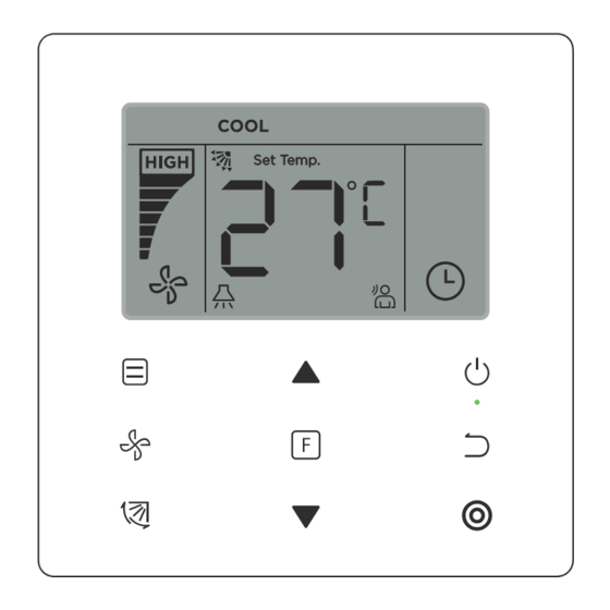
- Page 17 3. Iconos de la pantalla ⑤ ① ⑦ ② ⑧ ⑨ ⑩ ③ ④ ⑥ ① Recordatorio limpieza filtro ② Velocidad del ventilador ON/OFF ③ ④ Swing Ud. interior ⑤ Modo de funcionamiento ⑥ Función Función de bloqueo Transmisión de señal ⑦...
- Page 18 Figure 6.1 1) Pulse (ON/OFF), el indicador de funcionamiento " " del mando por cable se iluminará, y el icono de la unidad interior " " comenzará a girar en el display, para indicar que la unidad interior se ha puesto en marcha. (ver Figura 6.1) 2) Pulse (ON/OFF), el indicador de funcionamiento "...
- Page 19 Auto →Cool→Heat→Dry→Fan Figura 6.3 En el modo "Auto", "Cool", "Dry", o "Heat", pulse los botones ▲ y ▼ para ajustar la temperatura de consigna. (ver Figura 6.4) Figura 6.4 Nota: • El modo "Auto" y "Dry" no están disponibles para todos los modelos de aire acondicionado. En el modo "Auto", pulse ▲...
- Page 20 En el modo "Cool", "Heat" o "Fan", pulse (Velocidad del ventilador) para ajustar la velocidad del ventilador (ver Figura 6.5). Si el mando por cable tiene la configuración de 7 velocidades, pulse (Velocidad) para configurarla según la secuencia indicada en la Figura 6.6. →...
- Page 21 (Swing) para controlar el movimiento de las lamas verticales de la unidad interior (ver Pulse Figura 6.8). Cuando la unidad está encendida, la pantalla muestra el ángulo de oscilación actual de las lamas. (Swing), para cambiar el ángulo de abertura de las lamas, como muestra la Figura Pulse 6.9.
- Page 22 (Función) para activar las funciones correspondientes al modo de funcionamiento Pulse actual (ver Figura 6.10). • Pulse (Función) para ir a las funciones disponibles; la pantalla del mando con cable mostrará las opciones siguientes: " ", " ", " ", " ", "...
- Page 23 4-5-2 Silencio La función Silencio sirve para enviar a la unidad interior la señal Silencio. La unidad interior optimiza automáticamente el ruido que genera cuando la función Silencio está activada. • Activar/desactivar la función Silencio: pulse el botón para ir a la función Silencio (el icono parpadeará...
- Page 24 • Activar/desactivar la función ECO: pulse el botón para ir a la función ECO (el icono parpadeará en pantalla); a continuación, pulse para confirmar y activar la función o bien pulse para cancelar y desactivar la función (ver Figura 6.14). Inicio Parpadeo Apagado...
- Page 25 La función Follow Me del mando con cable se activa por defecto y su icono se ilumina en la pantalla cuando la función está activada. 1) Desactivar la función Follow Me: Mantenga pulsados los botones a la vez durante 5 segundos para desactivar la función Follow Me y que su correspondiente icono desaparezca de la pantalla.
- Page 26 Figura 6.16 2) Temporizador de apagado: Cuando haya completado la función «Timer On» pulse para pasar a la opción «Timer Off»; la pantalla mostrará la opción «0.0h Time Off» y el mensaje «Time Off» parpadeando. A continuación, pulse para confirmar. Pulse ▲ y ▼ para ajustar la hora de apagado y a continuación, pulse para confirmar y completar la acción.
- Page 27 4-6 Recordatorio de limpieza del filtro Figura 6.17 • Cuando se cumple el número de horas establecido para la limpieza del filtro, el icono se iluminará en la pantalla. • Mantenga pulsado el botón durante 5 segundos para que el icono desaparezca de la pantalla.
- Page 28 • Una o más de las funciones siguientes de la unidad interior quedarán bloqueadas cuando el icono se ilumine en la pantalla: mando a distancia inalámbrico, encendido/ apagado, valor mínimo de temperatura, valor máximo de temperatura, modo de funcionamiento, velocidad del ventilador y bloqueo del mando con cable. •...
- Page 29 Figura 7.1 2. Configuración y consulta de la dirección de la unidad interior • Si la unidad interior no tiene dirección, la pantalla mostrará el código FE y el mando por cable mostrará el código de error E9. • Para ir a la página de configuración de la dirección de la unidad interior, mantenga pulsados los botones ▲...
- Page 30 la dirección al valor deseado (el rango de dirección es 0-63). Pulse el botón para enviar el valor de la dirección actual a la unidad interior. En 60 segundos, el mando por cable saldrá de la página de ajuste de la dirección, o pulse el botón (Cancelar) para salir.
- Page 31 Tabla 5.1 Descripción Código del Parámetros a Valor por Observaciones del parámetro seleccionar defecto parámetro Cuando dos mandos con cable controlan FO: Mando con una unidad interior, la dirección debe ser cable principal Ajuste de la distinta. dirección F1: Mando con cable secundario 00: Refrigeración y...
- Page 32 Descripción Código del Valor por Parámetros a Observaciones del parámetro parámetro defecto seleccionar Si selecciona «On», el indicador de funcionamiento mostrará Ajustes para 00: Off si la unidad interior está encendida/apagada. encender/ Si selecciona «Off», el indicador de funcionamiento estará apagar el siempre apagado, independientemente de si la unidad interior 01: On...
-
Page 33: C12
Código del Parámetros Valor por Descripción Observaciones a seleccionar parámetro del parámetro defecto Parámetro Ajuste de compensación Según los de temperatura interruptores 00/01/02/ 1 y 5 6°C/ 2°C/ 4°C/ 6°C/ 0°C/ de dial de 03/04/FF Valor calefacción 43°F 36° F 39°F 43°F 32°... -
Page 34: Fapu
Código del Descripción Parámetros Valor por Observaciones parámetro del parámetro a seleccionar defecto Unidad inte- 00: Ninguno Ajuste del swing rior común horizontal ud. 01: Disponible interior FAPU: 00 Permite a la 00: No pantalla de la unidad interior 01: Sí recibir señales del mando a distancia. - Page 35 Código del Descripción Parámetros Valor por Observaciones parámetro del parámetro a seleccionar defecto Parámetro Apertura de la válvula de expan- Según los sión electrónica 00/01/02/ FF interruptores de dial Valor 72 96 en Calefacción de la PCB de la o en espera unidad interior Unidad de 00: Celsius...
- Page 36 Código del Parámetros Descripción Valor por Observaciones a seleccionar parámetro del parámetro defecto 0: Inválido 0.1-19.9HP: 0.1HP puede configurar 21- 40HP: 1HP Ajuste de puede configurar La unidad interior no puede cambiar el capacidad ajuste de capacidad cuando recibe 0. 42-80HP: 2HP puede configurar FF: en uso los...
- Page 37 1 Cuando la unidad interior y el mando con cable se comunican correctamente, los parámetros predeterminados de la tabla anterior se sincronizarán con los ajustes de la unidad interior. 2 Sólo para unidades de conductos de presión estática media. Capacidad 1.8 - 7.1kW 10Pa 20Pa...
- Page 38 4. Consulta Desde la página principal, mantenga pulsados los botones al mismo tiempo durante 5 segundos para acceder a la pagina de Consulta. Desde aquí podrá consultar los parámetros de funcionamiento de las unidades interior y exterior, así como la versión del programa del mando con cable.
- Page 39 Tabla 6.1 Parámetro mostrado en el mando por cable Dirección de la unidad exterior Temperatura (°C) ambiente exterior (T4) Temperatura media (°C) de T2/T2B corregida Temperatura (°C) del tubo principal del intercambiador de calor (T3) Temperatura (°C) de descarga del compresor A Temperatura (°C) de descarga del compresor B Corriente (A) del compresor Inverter A Corriente (A) del compresor Inverter B...
- Page 40 Parámetro mostrado en el mando durante la inspección de la ud exterior Temperatura (°C) del disipador térmico del módulo Inverter A(°C) Temperatura (°C) del disipador térmico del módulo Inverter B(°C) (reservado) Reservado Temperatura (°C) de la salida del intercambiador de placas (T6B) Temperatura (°C) de la entrada del intercambiador de placas (T6A) Grado de sobrecalentamiento de descarga del sistema Nº...
- Page 41 Parámetro mostrado en el mando durante la inspección de la ud exterior Reservado 2 Reservado 2 Tabla 6.2 Parámetro mostrado en el mando durante la inspección de la ud interior Dirección de comunicación de la unidad interior Capacidad (HP) de la ud. interior Dirección de red de la ud.
- Page 42 5. Códigos de error • Cuando se produzca un error de comunicación entre el mando con cable y la unidad interior, la pantalla del mando con cable mostrará el código de error E9. • Cuando se produce un fallo en la unidad interior o en la unidad exterior, la dirección de la unidad o unidades defectuosas aparecerá...
- Page 43 Tabla 7.2 Listado de códigos de error de la unidad exterior: Código Código Código de error y descripción Código de error y descripción de error de error Error de comunicación de la ud exterior Error de la fase PTC Protección de fase de Error en el sensor de temperatura (T6B) en la alimentación trifásica salida del intercambiador de calor de placas...
- Page 44 Listado de códigos de error de la unidad exterior: Código Código Código de error y descripción Código de error y descripción de error de error Fallo de protección Fallo del módulo Inverter del módulo Inverter Fallo protección P2 x Protección de baja tensión del bus de CC 3 veces en 60 minutos Fallo protección P4 x 3 veces Protección de baja tensión del bus de CC...
- Page 45 Resolución de problemas Tabla 8.1 Código de error y Causa posible Soluciones descripción La unidad interior no está encendida. Encienda la unidad interior. Apague la unidad interior y luego compruebe si la conexión del mando con cable es Error de conexión del mando con cable. correcta.
- Page 46 ● Read this manual carefully and be sure you understand the information before attempting to use the controller. ● Keep this manual where it is readily accessible after reading it through. ● If another user operates the controller in the future, be sure to hand over this manual to the new user.
- Page 47 Contents Installation ......................1 1. Safety Precautions ..................1 2. Accessories ..................... 3 3. Installation Procedure..................4 Operation ......................9 1. Safety Precautions ..................9 2. Parts of the Wired Controller ................. 11 3. Icons in the Display ..................13 4.
- Page 48 Installation 1. Safety Precautions Please read these Safety Precautions carefully before installing the wired controller. This manual classifies the precautions into WARNING and CAUTION. They both contain important information regarding safety. Be sure to follow all the precautions below. Identifier Meaning Failure to follow these instructions properly may result in personal...
- Page 49 ● Be sure to use only the specified accessories and parts for installation work. Failure to use the specified parts may result in the unit falling down, water leakage, electric shocks or fire. ● Install the wired controller on a foundation strong enough to withstand the weight of the wired controller.
- Page 50 2. Accessories Please check that you have all the following parts. Table 2.1 Name Remarks Schematic Qty. Used to install the wired Philips head screw, M4X25mm controller on the electrical Used to install the wired Plastic support bar controller on the electrical φ5X16mm Operation and Installation Manual...
- Page 51 3. Installation Procedure 3-1 Determine Where to Install the Wired Controller Make sure to refer to "1. Safety Precautions" to determine the location. 3-2 Structural Dimensions 20mm 86mm FOLLOW ME 60mm Figure 3.1 Figure 3.2 3-3 Rear Cover Installation 3-3-1 Insert a small slotted-head screwdriver into the bottom slot of the wired controller and rotate in the direction indicated to remove the rear cover of the wired controller.
- Page 52 Warning • When using the small slotted screwdriver to open the rear cover of the wired controller, be careful not to damage the PCB inside. • Do not touch the PCB of the wired controller. 3-3-2 Use a cutting tool to adjust the height of the two plastic support bars (accessory 2) to match the standard length of the screw pillars of the electrical box to the wall surface.
- Page 53 3-3-4 Take the shielded wiring that has been pre-embedded in the wall, and thread it through the wire hole of the rear cover. Use the Philips head screws (accessory 1) to fix the rear cover of the wired controller to the electrical box via the support bars. Make sure that the rear cover is not deformed after being installed (see Figure 3.6).
- Page 54 3-4-2 Communication wiring • The communication between the indoor unit and wired controller is bi-directional communication. The parameters displayed on the wired controller are refreshed in real time according to changes in the parameters of the indoor unit. • X1 and X2 are terminals to connect the indoor unit and wired controller. There is no polarity between X1 and X2.
- Page 55 "Secondary". Refer to "Field setting". The default setting of the wired controller is set to main controller. • This method is only available for two ECRP86EKD wired controllers. 3.5 Install Main Body of Wired Controller Take the shielded wiring that has been pre-embedded in the wall and pass it through the wiring hole of the rear cover of the wired controller.
- Page 56 X1 X2 Figure 3.10 Figure 3.9 △ Caution • During installation, reserve a certain length for the connecting shielded wiring to make it easier to remove the wired controller for maintenance. Operation 1. Safety Precautions This controller is not intended to be used by persons, including children, with reduced physical, sensory or mental capabilities or lack of experience and knowledge, unless they are supervised or have been given instructions on how to use the controller by a person responsible for their safety.
- Page 57 Identifier Meaning Failure to follow these instructions properly may result in personal Warning injury or loss of life. Failure to observe these instructions properly may result in property damage or personal injury, which may be serious depending on the Caution circumstances.
- Page 58 Caution ● Do not play with the wired controller. Accidental operation by a child may result in impairment of bodily functions and harm health. ● Never disassemble the wired controller. Pressing the interior parts may result in electric shocks or fire. Consult your dealer or authorized contractor for internal inspections and adjustments.
- Page 59 Table 4.1 Button Functions To set the operating mode: Auto → Cool→ Heat→ Dry→ Fan Mode Fan speed To set the fan speed. Swing To set the swing function. Function To switch to functions that can be set in the current mode. Adjust upwards To adjust temperature setting and timing (for timer) upwards.
- Page 60 3. Icons in the Display ⑤ ① ⑦ ② ⑧ ⑨ ⑩ ③ ④ ⑥ ① ② Clean filter reminder indicator Fan speed Indoor unit ON/OFF ③ ④ Swing ⑤ Operating mode ⑥ Function ⑦ ⑧ Lock indicator Signal transmission indicator ⑨...
- Page 61 Figure 6.1 1) Press (ON/OFF) button, and the Operating Indicator " " on the wired controller will light up, while the ON/OFF icon " " of the indoor unit on the display will spin to indicate that the indoor unit has started running. (see Figure 6.1) 2) Press (ON/OFF) button again, and the Operating Indicator "...
- Page 62 Auto →Cool→Heat→Dry→Fan Figure 6.3 In the "Auto", "Cool", "Dry", or "Heat" mode, press ▲ and ▼ buttons to adjust to the setting temperature. (see Figure 6.4) Figure 6.4 Note: • The "Auto" mode is not available for all air conditioner models. •...
- Page 63 In the "Cool", "Heat" or "Fan" mode, press (Fan speed) button to set the operating fan speed (see Figure 6.5). If the wired controller is configured with seven fan speeds, press (Fan speed) button to set the fan speed in turn as shown in Figure 6.6. →...
- Page 64 Press (Swing) button to control the swing of the vertical louver of indoor unit (see Figure 6.8). When the unit is on, the display icon shows the swing angle of the current louver. (Swing) button, and the louver switches from the current angle to the angles in turn Press as shown in Figure 6.9.
- Page 65 Press (Function) button to switch to the function that can be set in the current mode (see Figure 6.10). • Press (Function) button to go to the function setting, and the display on the wired " (reserved). Alternatively, you controller will show in turns: " ", "...
- Page 66 4-5-2 Silent The "Silent" function is used to send the "Silent" control signal to the indoor unit. The indoor unit automatically optimizes the noise it generates when it is in the "Silent" state. • Turn on/off the "Silent" function: press (Function) button to switch to the "Silent"...
- Page 67 • Turn on/off the "ECO" function: press (Function) button to switch to the "ECO" function " blinks), and press (" (Confirm) button to turn on the function or (Cancel) button to turn off the function (see Figure 6.14). Start Blink Figure 6.14 Note: •...
- Page 68 The "Follow Me" function of the wired controller is on by default, and its icon lights up when the function is on. (Confirm) buttons at the same time, and 1) Turn off "Follow Me": Press (Swing) and hold for 5 seconds to turn off the "Follow Me" function, and its icon disappear. 2) Turn on "Follow Me": When the "Follow Me"...
- Page 69 Figure 6.16 2) "Timer Off" setting: Once the "Timer On" setting is completed, press (Function) button to go to the "Timer Off" setting, the display will show "0.0h Time Off", and the words (Confirm) button to go to the timer setting, and press ▲ and "Time Of"...
- Page 70 4-6 Clean Filter Reminder Figure 6.17 • When the operating time reaches the preset time, the Filter icon " " lights up to remind users to clean the filter. • Press and hold (Swing) button for 5 seconds to remove the Filter icon " ".
- Page 71 • One or more of the following functions of the indoor unit are locked when the icon " " lights up on the display: wireless remote controller, on/off state, lowest cooling set temperature, highest set temperature, mode, fan speed, wired controller lock. •...
- Page 72 Figure 7.1 2. Query and Set the Indoor Unit Address • If the indoor unit has no address, the display will show "FE", and the wired controller will display an E9 error. • Press and hold ▲ and ▼ buttons for 8 seconds to go to the page to set the indoor unit (Cancel) button to exit the settings page.
- Page 73 adjust the address to the required value (address range is 0-63). press (Confirm) button to send the current address value to the indoor unit. In 60 seconds, the wired controller will exit the address setting page, or press (Cancel) button to exit the address setting page. •...
- Page 74 Table 5.1 Default Parameter Parameter Select Remarks Code Content Parameters Value If two wired controllers control one indoor unit, F0: Main wired the address must be different controller Address Setting F1: Secondary wired controller 00: Cooling and Cooling Only/Cooling Heating Heating mode is not available in cooling only and Heating 01: Cooling...
- Page 75 Default Parameter Parameter Select Remarks Code Content Parameters Value Select "On" and the operating indicator will show the Settings to 00: Off ON/OFF state of the indoor unit. turn on/off Select "Off" and the operating indicator will always operating 01: On be off regardless the indoor unit is...
-
Page 76: Table Of Contents
Default Parameter Parameter Select Remarks Code Content Parameters Value Parameter Based on Indoor unit the dial heating 00/01/02/ switches 1 and 5 temperature 4°C/ 0°C/ 03/04/FF Value 6°C/ 2°C/ 6°C/ in the compensation 43°F 43°F Represents 36° F 39°F 32° F main PCB setting of the... -
Page 77: 00: None
Default Parameter Parameter Select Remarks Code Content Parameters Value 00: None Common Indoor unit Indoor Unit: horizontal swing 01: Available setting FAPU: 00 Display of 00: No indoor unit to receive the 01: Yes remote control signals 00: No Buzzer of the 01: Yes indoor unit rings Follow Me in... -
Page 78: Unit
Default Parameter Parameter Select Remarks Code Content Parameters Value Parameter Select opening of electronic Based on the dial 00/01/02/FF expansion valve 72 96 Value switches in the in Heating or Represents main PCB of the Standby mode indoor unit 00: Celsius Temperature 00/01 Unit... - Page 79 Default Parameter Parameter Select Remarks Code Content Parameters Value 0:Invalid value 0.1-19.9HP: 0.1HP can set 21-40HP: Capacity Indoor cannot change capcacity seteting when 1HP can set setting receive 0. 42-80HP: 2HP can set FF:using indoor switch numbers send wired control setting parameter to indoor unit within two hours of power on (setting parameter:C9-C19,C21-23,C28) 00:invalid drain pump...
-
Page 80: Of The
1 Once the indoor unit and wired controller communicate successfully, the default parameters of the above table will synchronize to the indoor unit settings. 2 Only for medium static duct unit Capacity 1.8 - 7.1kW 40Pa 50Pa 50Pa 50Pa 50Pa 50Pa 10Pa 20Pa... - Page 81 4. Query Operations In the main page, press and hold (Fan speed) and (Confirm) buttons at the same time for 5 seconds to go to the query page. You can query the check operation parameters of the outdoor and indoor units as well as the program version of the wired controller. Figure 7.4 Press ▲...
- Page 82 Table 6.1 Parameter displayed on the wired controller during ODU spot check ODU address Outdoor ambient(T4) temperature (°C) T2/T2B average Temp. (corrected) (°C) Main heat exchanger pipe(T3) temperature (°C) Discharge Temp. of compressor A(°C) Discharge Temp. of compressor B(°C) Inverter compressor A current (A) Inverter compressor B current (A) Reserved Fan speed...
- Page 83 Parameter displayed on the wired controller during ODU spot check Inverter-module heatsink Temp. A(°C) Inverter-module heatsink Temp. B(°C) (reserved) Reserved Plate heat exchanger outlet (T6B) temperature (°C) Plate heat exchanger inlet (T6A) temperature (°C) System discharge superheat degree Number of operating indoor units (in case of virtual addresses, this is the number of units with the virtual addresses included) High pressure of system Low pressure of the system (reserved)
- Page 84 Parameter displayed on the wired controller during ODU spot check Reserved 2 Reserved 2 Table 6.2 Parameter displayed on the wired controller during IDU spot check IDU communication address Capacity (HP) of IDU IDU network address (the same as the communication address) Set temperature Ts Room temperature T1 Actual T2 indoor temperature...
- Page 85 5. Error Display • When there is a communication error between the wired controller and the indoor unit, the wired controller will show the error code "E9", an indication of a communication failure in wired controller. • When the indoor or outdoor unit fails, the display of the wired controller shows the address of faulty unit(s) in the timer area, and the error code in the temperature area.
- Page 86 Table 7.2 List of ODU error codes: Error Definition and Error Error Error Definition and Description Description Code Code ODU communication fault PTC error Three-phase power supply Error in temperature sensor at T6B phase protection plate heat exchanger outlet Communication error between Error in temperature sensor at T6A indoor and outdoor units plate heat exchanger inlet...
- Page 87 List of ODU error codes: Error Definition and Error Error Error Definition and Description Description Code Code Inverter module protection Inverter module fault fault 3X P2 protection fault in 60 DC bus low voltage protection minutes 3X P4 protection fault in 100 DC bus high voltage protection minutes IDU qty decrease fault...
-
Page 88: The Indoor Unit
Troubleshooting Table 8.1 Error code and Possible Causes Possible Solutions description IDU is not powered on Power on the IDU. First power off the IDU, and then check if Wired controller connection error the wired controller connection is correct. No display on the See Section 3.4 on the wiring requirements. - Page 89 Scan for manual in other languages and further updates: Manuel dans d'autres langues et mis à jour: Manual em outras línguas e actualizações: EAS ELECTRIC SMART TECHNOLOGY, S.L.U. P.I. San Carlos, Camino de la Sierra S/N, Parc. 11 03370 Redován - Alicante (SPAIN)
Need help?
Do you have a question about the ECRP86EKD and is the answer not in the manual?
Questions and answers