Advertisement
Available languages
Available languages
Quick Links
MANDO POR CABLE
WIRED CONTROLLER
Serie
EMCH R32
MANUAL DE INSTRUCCIONES
OPERATING MANUAL
Escanee para ver este manual en otros idiomas y actualizaciones
Scan for manual in other languages and further updates
Manuel dans d'autres langues et mis à jour
Manual em outras línguas e actualizações
V.1
Advertisement

Related Manuals for EAS Electric EMCH R32 Series


Summary of Contents for EAS Electric EMCH R32 Series
- Page 1 MANDO POR CABLE WIRED CONTROLLER Serie EMCH R32 MANUAL DE INSTRUCCIONES OPERATING MANUAL Escanee para ver este manual en otros idiomas y actualizaciones Scan for manual in other languages and further updates Manuel dans d'autres langues et mis à jour Manual em outras línguas e actualizações...
- Page 2 INSTRUCCIONES DE SEGURIDAD Contenido ASPECTO DEL MANDO USO DE LAS PÁGINAS DE INICIO ESTRUCTURA DE MENÚS USO BÁSICO FUNCIONAMIENTO INSTRUCCIONES DE CONFIGURACIÓN DE RED Este manual detalla todas las instrucciones que deben tenerse en cuenta para el uso del aparato. Para garantizar un funcionamiento correcto del mando, lea atentamente este manual antes de usarlo.
- Page 3 1 PRECAUCIONES GENERALES DE SEGURIDAD 1.1 Sobre la documentación La documentación original está escrita en inglés. Los demás idiomas son traducciones. Las precauciones descritas en este documento cubren temas muy importantes, sígalas cuidadosamente. Todas las actividades descritas en el manual de instalación deben ser realizadas por un instalador autorizado.
- Page 4 ADVERTENCIA Indica una situación que puede resultar en la muerte o lesiones graves. ATENCIÓN Indica una situación que podría provocar lesiones leves o moderadas. NOTA Indica una situación que podría provocar daños al equipo o a la propiedad. INFORMACIÓN Indica consejos útiles o información adicional. 1.2 Para el usuario Si no está...
- Page 5 El aparato no está destinado a ser utilizado por personas, incluidos los niños, con capacidades físicas, sensoriales o mentales reducidas, falta experiencia conocimientos, a menos que hayan recibido supervisión o instrucciones sobre el uso del aparato por parte de una persona responsable de su seguridad.
- Page 6 Las unidades están marcadas con el siguiente símbolo: Esto significa que los productos eléctricos y electrónicos no pueden mezclarse con los residuos domésticos no clasificados. No intente desmontar el sistema usted mismo: el desmontaje del sistema, el tratamiento del refrigerante, del aceite y de otras piezas debe ser realizado por un instalador autorizado y debe cumplir con la legislación vigente.
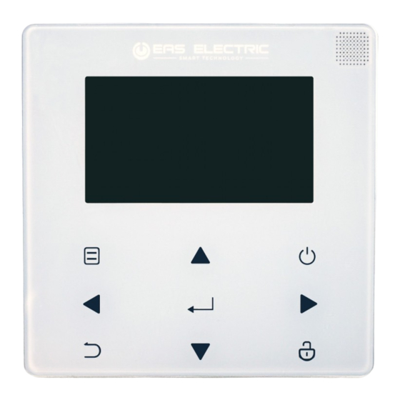
- Page 7 2 INTERFAZ DE USUARIO 2.1 Apariencia del mando por cable Acceso a la estructura de menú desde la pág. de inicio Enciende o apaga el modo de climatización o modo ACS; enciende o apaga Desplazar el una función en la cursor por el estructura de display/despla-...
- Page 8 2.2 Iconos de estado Bloqueo Programación semanal En la siguiente acción programada, la Icono temporizador temperatura deseada disminuirá. la temp. deseada Temp. ambiente exterior no cambiará. la temp. deseada Icono WLAN disminuirá la temp. deseada Agua caliente sanitaria aumentará Func. de desinfección Fan coil activada Radiador...
- Page 9 3 USO DE LAS PÁGINAS DE INICIO 3.1 Sobre las páginas de inicio Seleccione su idioma y pulse “ ” para acceder a las páginas de inicio. Si no pulsa “ ” en 60 segundos, el sistema se iniciará en el idioma que esté...
- Page 10 Página de inicio 1: Si la TEMP. FLUJO AGUA está configurada en SÍ y TEMP. SALA está en NON, el sistema incluye las funciones de calefacción, refrigeración y ACS, y aparecerá la página de inicio 1: Sin función ACS o ACS Modo ACS configurado configurada no disponible...
- Page 11 Página de inicio 2: Si TEMP. FLUJO AGUA está configurado en NON y TEMP. SALA en SÍ, y el sistema tiene funciones de calefacción, refrigeración y ACS, se mostrará la página de inicio 2: Sin función ACS o Modo ACS está disponible modo ACS no disponible El mando por cable debe instalarse en la estancia donde se...
- Page 12 Página de inicio 3 : Si el TERMOSTATO DE SALA se configura en DOBLE ZONA, y el sistema tiene las funciones de calefacción, refrigeración y ACS, habrá una página de inicio y una página adicional: Página principal Página principal Página adicional Página adicional Modo ACS configurado Sin modo ACS o modo...
- Page 13 Página de inicio 4: Si la unidad no tiene función ACS o ACS está configurado como no disponible, TEMP. FLUJO AGUA y TEMP. SALA están ambos configu- rados en SÍ y el sistema dispone de las funciones de calefacción y refrigeración, habrá...
- Page 14 NOTA Todas las imágenes del manual tienen fines ilustrativos, las páginas reales pueden diferir. TEMP. FLUJO DE AGUA, TEMP. SALA y ZONA DOBLE se configuran en la sección FOR SERVICEMAN, y no se recomienda que nadie que no sea profesional acceda a este apartado.
- Page 15 4 ESTRUCTURA DEL MENÚ 4.1 Sobre la estructura del menú Puede usar la estructura del menú para leer y configurar ajustes que NO están destinados al uso diario, y puede encontrar los métodos detallados de funcionamiento sobre la estructura del menú en este manual.
- Page 16 5 USO BÁSICO 5.1 Desbloqueo de la pantalla El icono " " mostrado en la pantalla indica que el mando está bloqueado. Mantenga pulsado " " hasta que el icono desaparezca, y podrá utilizar el mando. Mantenga pulsado " " El mando se bloqueará...
- Page 17 5.2 Controles de encendido/apagado Use el mando para encender o apagar el modo de funcionamiento (calefacción , refrigeración , modo AUTO , modo ACS ) de la unidad. 1) La unidad tiene función ACS y está configurada como disponible. Pulse " "...
- Page 18 2) La unidad no tiene función ACS o está configurada como no disponible. El método de encendido y apagado de los modos de funcionamiento es similar en el resto de menús.
- Page 19 5.3 Ajuste de la temperatura Use ''◄'', ''►'' para seleccionar el modo de funcionamiento.
- Page 20 Use ''▼'', ''▲'' para ajustar el valor de temperatura. Los métodos de ajuste de temperatura son similares en otros menús, incluso para las unidades que no tienen función de ACS o en las que el modo ACS está configurado como no disponible.
- Page 21 5.4 Ajuste del modo de funcionamiento Vaya a " " > "MODO DE FUNCIONAMIENTO'', y pulse " ", se mostrará la siguiente página: MODO DE FUNCIONAMIENTO Ajuste del modo de funcionamiento: CALOR FRÍO AUTO CONFIRMAR Hay tres opciones de modo en la interfaz del mando: modo CALOR, modo FRÍO y modo AUTO.
- Page 22 Si el modo FRÍO(CALOR) está configurado en NON, sólo puede seleccionarse un modo en la interfaz del mando, y aparecerá la siguiente página: MODO DE FUNCIONAMIENTO MODO DE FUNCIONAMIENTO El modo de funcionamiento El modo de funcionamiento solo puede ser calor solo puede ser frío: CALOR FRÍO...
- Page 23 Cuando "TERMOSTATO DE SALA" está configurado en "UNA ZONE" o "DOBLE ZONA" en "FOR SERVICEMAN", la página de "MODO DE FUNCIONAMIENTO" es como se muestra: MODO DE FUNCIONAMIENTO Ajuste del modo de funcionamiento: CALOR FRÍO AUTO CONFIRMAR Bajo esta circunstancia, se puede seleccionar el modo CALOR y FRÍO, pero no AUTO.
- Page 24 6 FUNCIONAMIENTO 6.1 TEMPERATURA PRECONFIGURADA Este menú contiene 3 apartados: TEMP. PREC., AJ. TEMP. CLIMA y MODO ECO. 6.1.1 TEMP. PREC. La función TEMP. PREC. (TEMPERATURA PRECONFIGURADA) se usa para configurar distintas temperaturas en distintos momentos cuando el modo de refrigeración o calefacción están activos. La función TEMP.
- Page 25 Use ''◄'', ''► '', ''▼'', ''▲'' para desplazarse y "▼", "▲" para ajustar la hora y la temperatura, pulse " " para seleccionar el temporizador. Pueden elegirse 6 temporizadores. ( habilita el temporizador deshabilita el temporizador) TEMP. PRECONFIG. TEMP. AJ. TEMP. MODO PREC.
- Page 26 La temperatura cambiará según el siguiente esquema: TEMP. 40°C 35°C 8:00 12:00 1 5:00 1 8:00 20:00 23:00 INFORMACIÓN Cuando se activa la doble zona, la función de TEMP. PREC. sólo funciona para la zona 1. La función TEMP. PREC. puede usarse en modo calefacción y refrigeración, pero si se cambia entre un modo y otro, la función debe volver a configurarse.
- Page 27 6.1.2 AJ. TEMP. CLIMA AJ. TEMP. CLIMA (AJUSTE DE TEMPERATURA SEGÚN CLIMA) se usa para predeterminar la temperatura del caudal de agua deseada según la temperatura exterior. Tomando el modo de calefacción como ejemplo: la función AJ. TEMP. CLIMA puede disminuir la temperatura de consigna del caudal de agua cuando la temperatura exterior aumenta.
- Page 28 Use " " para activar o desactivar la curva de temperatura. Si "ZONE1 C-MODE LOW TEMP." está activado, se activa el modo refrigeración en la zona 1, se mostrará la siguiente página: AJ. TEMP. CLIMA TIPO AJ. TEMP. CLIMA: 1 2 3 5 6 7 8 9 CONFIRMAR El método de funcionamiento de otras curvas de temperatura es...
- Page 29 TEMP. PRECONFIG. TEMP. PRECONFIG. TEMP. AJ. TEMP. MODO TEMP. AJ. TEMP. MODO CLIMA CLIMA PREC. PREC. 0°C ZONE 1 C-MODE LOW TEMP. ZONE 1 C-MODE CURVE OFFSET ZONE 1 H-MODE LOW TEMP. ZONE 1 H-MODE CURVE OFFSET 0°C 0°C ZONE 2 C-MODE LOW TEMP. ZONE 2 C-MODE CURVE OFFSET 0°C ZONE 2 H-MODE LOW TEMP.
- Page 30 Temperatura de agua en modo calefacción bajo (T4 = temperatura ambiente, T1S = temperatura de agua de consigna) ≤ - 20 - 19 - 18 - 17 - 16 - 15 - 14 - 13 - 12 - 11 - 10 1- T1S 2- T1S 3- T1S...
- Page 31 Curva de ajuste automático La curva de ajuste automático es la novena curva, según este método de cálculo: T1SETH1 T1SETH2 T4H1 T4H2 En los ajustes del mando por cable, si T4H2<T4H1, se intercambia su valor; si T1SETH1<T1SETH2, se intercambia su valor. (T1SETH1, T1SETH2,T4H1,T4H2 puede ajustarse en "FOR SERVICEMAN"...
- Page 32 Temperatura agua modo refrigeración-alto - 10≤ T4<15 15≤ T4<22 22≤ T4<30 30 ≤ T4 1- T1S 2- T1S 3- T1S 4- T1S 5- T1S 6- T1S 7- T1S 8- T1S Curva de ajuste automático La curva de ajuste automático es la novena curva, según este método de cálculo: T1SETC1 T1SETC2...
- Page 33 6.1.3 MODO ECO El MODO ECO se usa para ahorrar energía. "> ''TEMP. PRECONFIG.'' >"MODO ECO". Pulse '' Vaya a " y se mostrará la siguiente página: TEMP. PRECONFIG. TEMP. AJ. TEMP. MODO PREC. CLIMA ESTADO ACTUAL TEMPORIZ. ECO 08:00 INICIO 9 1 0 0 ON/OFF...
- Page 34 Use " " para activar o desactivar en "ESTADO ACTUAL" o "TEMPORIZ. ECO" , y use ''▼'', ''▲'' para ajustar la hora de inicio y de fin. TEMP. PRECONFIG. TEMP. WEATHER TEMP. TEMP.SET MODE CURRENT STATE ECO TIMER 08:00 START ADJUST INFORMACIÓN El MODO ECO sólo es válido en modo calefacción (una zona).
- Page 35 6.2 AGUA CALIENTE SANITARIA (ACS) Los parámetros de "AGUA CALIENTE SANITARIA (ACS)" sólo pueden configurarse cuando la unidad tiene función de ACS y está configurada como disponible. Si la unidad no tiene función de ACS o está configurada como no disponible, no se mostrará "AGUA CALIENTE SANITARIA (ACS)"...
- Page 36 Use " " para activar o desactivar "ESTADO ACTUAL", y ''▼'', ''▲'' para ajustar la fecha de funcionamiento y la hora de inicio de la función de desinfección. Ejemplo: Si "DÍA FUNCION." está configurado en VIERNES e "INICIO" se ajusta a las 23:00, la función de desinfección se activará...
- Page 37 6.2.3 CALENTADOR DEL DEPÓSITO La función del CALENT. DEPÓS. se usa para forzar la puesta en marcha de la resistencia del depósito para calentar el agua almacenada. La función de CALENT. DEPÓS. puede usarse para calentar el agua incluso si hay un fallo de la bomba de calor. Esta función sólo puede usarse si se selecciona "FUNCIÓN TBH"...
- Page 38 INFORMACIÓN Si "ESTADO ACTUAL" está en OFF, CALENT. DEPÓS. es inválido. Si la T5 (sonda de temperatura del depósito) falle, el calentador del depósito será inválido. La función sólo es válida tras configurarla. 6.2.4 BOMBA ACS La función de BOMBA ACS se usa para devolver agua a la red de agua.
- Page 39 Use ''◄", ''►'', ''▼'', ''▲'' para desplazarse y ''▼'', ''▲'' para ajustar la hora de inicio. Pulse " " para seleccionar el temporizador. Pueden configurarse 12 temporizadores ( = temporizador activado = temporizador desactivado.) AGUA CALIENTE SANITARIA (ACS) CALENT. BOMBA DESIN- FECTAR RÁPIDO...
- Page 40 TIEMPO FUNC. PUMP_D está configurado en 30 minutos (TIEMPO FUNC. PUMP_D puede configurarse en "AJ. MODO ACS" en "FOR SERVICEMAN"). La bomba funcionará según el siguiente esquema: BOMBA 6:00 6:30 7:00 7:30 8:00 8:30 9:00 9:30 6.3 PROGRAMACIÓN El menú PROGRAMACIÓN contiene los siguientes apartados: 1) TEMPORIZADOR 2) PROG.
- Page 41 PROGRAMACIÓN PROG. COMPROB. CANCEL. TEMP. SEMANAL PROG. TEMP. INICIO MODO TEMP 00:00 00:00 HEAT 30℃ 00:00 00:00 HEAT 30℃ 00:00 00:00 HEAT 30℃ UNA ZONA es válido PROG. ZONA2 PROG. ZONA1 PROG. COMPROB. CANCEL. PROG. COMPROB. CANCEL. TEMP. TEMP. SEMANAL PROG.
- Page 42 Vaya a " "> "PROGRAMACIÓN">"TEMP". Pulse '' '', se mostrará la siguiente página: PROGRAMACIÓN PROG. COMPROB. CANCEL TEMP. SEMANAL PROG. TEMP. INICIO MODO TEMP 00:00 00:00 HEAT 40℃ 00:00 00:00 HEAT 40℃ 00:00 00:00 HEAT 40℃ Use ''◄", ''►'', ''▼'', ''▲'' para desplazarse y ''▼", ''▲'' para ajustar la hora de inicio/fin, el modo y temperatura de funcionamiento, y pulse "...
- Page 43 La unidad funcionará según este esquema: 6.3.2 PROG. SEMANAL (Tomando UNA ZONA como ejemplo) La función de PROG. SEMANAL se usa para configurar distintos modos y temperaturas de funcionamiento en una misma semana (un día o más). Si se configuran "PROG. SEMANAL" y "TEMP.", y el temporizador se configura más tarde que la programación semanal, será...
- Page 44 Pulse '' '' de nuevo, “LUN” se marca como se muestra más abajo, lo que significa que se ha seleccionado el lunes. PROGRAMACIÓN PROG. COMPROB. CANCEL TEMP. SEMANAL PROG. TEMP. LUN. MAR. MIE. JUE. VIE. SAB. DOM. CONF. CANCEL LUN SELECC Luego use "...
- Page 45 6.3.3 COMPROB. PROG. (UNA ZONA como ejemplo) La función de COMPROB. PROG. se usa para comprobar la programa- ción semanal. Vaya a " " > ''PROGRAMACIÓN" > "COMPROB. PROG.". Pulse '' '' y se mostrará la siguiente página: COMPROB. PROG. SEMANAL DÍA MODO AJ.
- Page 46 6.4 OPCIONES OPCIONES contiene los siguientes apartados: 1) MODO SILENCIO 2) VACACIONES FUERA 3) VACACIONES EN CASA 4) CALENTADOR AUXILIAR 6.4.1 MODO SILENCIO La función MODO SILENCIO se usa para reducir el sonido del funcionamiento de la unidad, aunque también se reduce la capacidad de refrigeración o calefacción del sistema.
- Page 47 Use '' '' para activar o desactivar el estado actual del MODO SILENCIO, Temp1 y Temp2, y "▼", "▲" para seleccionar el nivel de silencio y ajustar la hora de inicio/fin del temporizador. Hay dos métodos de uso del modo silencio: 1) Modo silencio permanente.
- Page 48 OPCIONES MODO VACAC. VACAC. CALENT. AUX. SILENC. FUERA EN CASA ESTADO ACTUAL MODO ACS DESINFECT. MODO CALEF. ON/OFF Use '' '' para activar o desactivar el estado actual de VACACIO- NES FUERA, el modo CALEF. (modo ACS) y modo DESINFECCIÓN, use"▼", "▲"...
- Page 49 6.4.3 VACACIONES EN CASA La función de VACAC. EN CASA se usa para configurar distintos modos de funcionamiento y temperatura durante las vacaciones en casa. Vaya a " " > "OPCIONES" > "VACAC. EN CASA". Pulse '' '' y se mostrará...
- Page 50 PROGRAMACIÓN VACAC. VACAC. MODO CALENT. FUERA EN CASA SILENC. INICIO MODO TEMP 00:00 00:00 HEAT 30℃ 00:00 00:00 HEAT 30℃ 00:00 00:00 HEAT 30℃ INFORMACIÓN Si se configuran "VACAC. FUERA" y "VACAC. EN CASA", y "VACAC. EN CASA" se configura más tarde que "VACAC. FUERA", la configuración de "VACAC.
- Page 51 6.4.4 CALENTADOR AUXILIAR La función del CALENTADOR AUXILIAR se usa para forzar la puesta en marcha de la resistencia auxiliar, y sólo puede usarse cuando IBH (calentador auxiliar) está configurado como válido con los interruptores DIP de la placa de control del módulo hidráulico o la función AHS (fuente de calor auxiliar) se configura como válida en "OTRA FUENTE DE CALOR"...
- Page 52 6.5 BLOQUEO INFANTIL 2.make La función de BLOQUEO INFANTIL se usa para evitar manipula- ciones indebidas por parte de niños. Si la unidad no tiene función 3.The 2 ACS o se configura ACS como no disponible, no se mostrarán "AJ. TEMP.
- Page 53 6.6 INFORMACIÓN DE SERVICIO sure you are next to home appliances. INFORMACIÓN DE SERVICIO contiene el siguiente menú: 1. LLAMADA SERVICIO 2.4GHz band wireless signal is enabled on your wireless 2. CÓDIGO DE ERROR 3. PARÁMETROS 4. DISPLAY 6.6.1 LLAMADA SERVICIO La función de LLAMADA DE SERVICIO se usa para mostrar el número de teléfono o móvil del servicio técnico.
- Page 54 6.6.2 CÓDIGOS DE ERROR La función ERROR CODE se usa para mostrar cuándo ha ocurrido el fallo o protección y muestra el significado del código de error. s router. Vaya a " ">"INFORMACIÓN DE SERVICIO" >"CÓDIGO ERROR", pulse " " y se mostrará la siguiente página: INFORMACIÓN SERVICIO LLAMADA CÓDIGO...
- Page 55 6.6.3 PARÁMETROS La función PARÁMETRO se usa para mostrar los parámetros principales. Vaya a " " > "INFORMACIÓN DE SERVICIO" > "PARÁMETROS" y se mostrará la siguiente página: INFORMACIÓN SERVICIO INFORMACIÓN SERVICIO LLAMADA CÓDIGO LLAMADA CÓDIGO PARÁMETRO DISPLAY PARÁMETRO DISPLAY SERV ERROR SERV...
- Page 56 6.7 PARÁMETROS DE FUNCIONAMIENTO La función PARÁMET. FUNCIONAM. sirve al instalador o técnico de servicio para revisar los parámetros de funcionamiento. Se puede comprobar la temperatura, caudal y presión de agua y otros parámetros en esta pantalla. INFORMACIÓN 1. CONSUM. ENERG. sólo sirve como referencia y no debe usarse para juzgar el consumo de potencia real.
- Page 57 6.8 PARA PERS. MANT. La función PARA PERS. MANT. sirve para configurar los paráme- tros. Vaya a " " > "PARA PERS. MANT.", la contraseña es "234". La función "PARA PERS. MANT." sólo está recomendada para profesionales. 6.9 VER SN La función VER SN sirve para ver el código SN.
- Page 58 7 GUÍAS DE CONFIGURACIÓN DE RED El mando por cable puede realizar un control inteligente mediante el módulo incorporado que recibe señales de control de la app. Antes de conectar la WLAN, compruebe si su router está activo y que el mando por cable está bien conectado a la señal inalámbrica.
- Page 59 Active la WLAN en la interfaz. Go to " "> "AJUSTES WLAN"> "MODO AP". Pulse " " y aparecerá la siguiente página: MODO AP ¿Desea activar la red WLAN y salir? SÍ CONFIRMAR Use ''◄'', ''►'' para desplazarse hasta "SÍ", pulse " "...
- Page 60 Para reiniciar los ajustes WLAN desde el mando, vaya a “ ”> “AJUSTES WLAN” > “RESTAB. AJ. WLAN” . Pulse " " y se mostrará la siguiente página: RESTAB. AJ. WLAN ¿Desea restablecer los ajustes WLAN y salir? SÍ CONFIRMAR Use ''◄'',...
- Page 61 7.2 Guías de conexión en red de aparatos domésticos smart Descargar app MSmartHome Escanee el código QR o busque "Comfort Home" en Google Play (Android) o App Store (iOS) para descargar la app;...
- Page 62 Registro o inicio de sesión Abra la app y cree una cuenta de usuario. Si ya dispone de una, inicie sesión. Login Enter email Login Enter password Login Wi-Fi Sta...
- Page 63 Add your appliance Añada su aparato Tap the "+"icon to add home appliance to Pulse el icono "+" para añadir el aparato que desea conectar con su cuenta. your MsmartLife account MSmartLife Indicatio atus Light Slowly flashing Waiting for connection Conecting with your quickly Flashing...
- Page 64 Connected to the network Conectado a la red Follow the instrctions in the app to set up the Siga las instrucciones de la app para configurar la conexión WiFi. Si la conexión de red falla, consulte el apartado de Wi-Fi connection. If the network connection consejos de la app.
- Page 65 Wi-Fi de 2.4GHZ, asegúrese de que se selecciona una red de 2.4GHz para realizar la conexión. Eas Electric recomienda que los nombres (SSID) de las redes WiFi contengan sólo caracteres alfanuméricos. Si se usan caracteres especiales, puntuación o espacios es posible que el SSID de la red no aparezca en la lista de redes disponibles para conectar la app.
- Page 66 Advertencia y solución de problemas de fallos en la red Cuando el producto esté conectado a la red, asegúrese de que el teléfono esté lo más cerca posible del producto. Por ahora sólo se admiten routers de banda de 2,4 GHz. No se recomienda utilizar caracteres especiales (puntua- ción, espacios, etc.) como parte del nombre de la WLAN.
-
Page 67: Table Of Contents
GENERAL SAFETY PRECAUTIONS Contents A GLANCE AT THE USER INTERFACE USING HOME PAGES MENU STRUCTURE BASIC USAGE OPERATION NETWORK CONFIGURATION GUIDELINES This manual details all the instructions that must be observed when using the appliance. To ensure correct operation of the control unit, please read this manual carefully before use. -
Page 68: General Safety Precautions
1 GENERAL SAFETY PRECAUTIONS 1.1 About the documentation The original documentation is written in English. All other languages are translations. The precautions described in this document cover very important topics, follow them carefully. All activities described in the installation manual must be performed by an authorized installer. - Page 69 WARNING Indicates a situation that could result in death or serious injury. CAUTION Indicates a situation that could result in minor or moderate injury. NOTE Indicates a situation that could result in equipment or property damage. INFORMATION Indicates useful tips or additional information. 1.2 For the user If you are not sure how to operate the unit, contact your installer.
- Page 70 The appliance is not intended for use by persons, including children, with reduced physical, sensory mental capabilities, or lack of experience and knowledge, unless they have been given supervision or instruction concerning use of the appliance by a person responsible for their safety. Children must be supervised to ensure that they do not play with the product.
- Page 71 Units are marked with the following symbol: This means that electrical and electronic products may not be mixed with unsorted household waste. Do not try to dismantle the system yourself: the dismantling of the system, treatment of the refrigerant, of oil and of other parts must be done by an authorized installer and must comply with applicable legislation.
-
Page 72: A Glance At The User Interface
2 A GLANCE OF THE USER INTERFACE 2.1 The appearance of the wired controller Enter the menu structure from the home page Turn on or off the space operation mode or DHW mode; turn on or off the function Navigate the in the menu cursor on the structure... - Page 73 2.2 Status icons Lock icon Weekly schedule icon At the next scheduled action, the Timer icon desired temp. will decrease. the desired temp. Outdoor ambient temp. will not change. the desired temp. will WLAN icon decrease. the desired temp. Domestic hot water will increase.
-
Page 74: Using Home
3 USING HOME PAGES 3.1 About home pages Select your preferred language, then press “ ” to enter the home pages. If you don't press “ ” in 60 seconds, the system will enter in the currently selected language. Based on the system layout, the following home pages may appear:... - Page 75 Home page 1: If the WATER FLOW TEMP. is set YES and ROOM TEMP. is set NON, the system has the functions including space heating, space cooling and domestic hot water, home page 1 will appear: Without DHW function DHW mode is set available or DHW mode is set unavailable...
- Page 76 Home page 2: If the WATER FLOW TEMP. is set NON and ROOM TEMP. is set YES, the system has the functions including space heating, space cooling and domestic hot water, home page 2 will appear: Without DHW function DHW mode is set available or DHW mode is set unavailable The wired controller should be installed in the room to...
- Page 77 Home page 3 : If the ROOM THERMOSTAT is set DOUBLE ZONE, the system has the functions including space heating, space cooling and domestic hot water, there will be main page and additional page: Main page Main page Addition page Addition page Without DHW function DHW mode is set available...
- Page 78 Home page 4: If the unit has no DHW function or DHW is set unavailable, WATER FLOW TEMP. and ROOM TEMP. are both set YES, the system has the functions including space heating and space cooling, there will be main page and additional page:...
- Page 79 NOTE All the pictures in the manual are for explanation, the actual pages in the screen may have some difference. WATER FLOW TEMP., ROOM TEMP. and DOUBLE ZONE are set in FOR SERVICEMAN, it is not recommended for non- professionals to enter FOR SERVICEMAN.
-
Page 80: Menu Structure
4 MENU STRUCTURE 4.1 About the menu structure You can use the menu structure to read out and configure settings that are NOT meant for daily usage, and you can find the detailed operation methods about the menu structure in this manual. If the unit has no DHW function or DHW mode is set unavailable, there is no DOMESTIC HOT WATER(DHW) menu in the interface. -
Page 81: Basic Usage
5 BASIC USAGE 5.1 Screen unlock The icon " "showing on the screen means the controller is locked. Long press " ", it will disappear, then the controller can be used. Long press " " The controller will be locked if it has not been operated for a long time (about 120 seconds). - Page 82 5.2 Turning ON/OFF controls Use the controller to turn on or off the operation mode (heat mode cool mode , auto mode , DHW mode ) of the unit. 1) The unit has DHW function and DHW mode is set available. Press " "...
- Page 83 2) The unit has no DHW function or DHW mode is set unavailable. The operation methods of turning on or off the operation mode in other menus is similar.
- Page 84 5.3 Adjusting the temperature Use ''◄'', ''►'' to select the operating mode.
- Page 85 Use ''▼'', ''▲'' to adjust the temperature value. The operation methods of adjusting the temperature in other menus (including that the unit has no DHW function or DHW mode is set unavailable) is similar.
- Page 86 5.4 Adjusting the operation mode Go to " " > "OPERATION MODE'', then press " ", the following page will appear: OPERATION MODE Operation mode setting: HEAT AUTO COOL CONFIRM There are three operation modes on the controller interface: HEAT mode, COOL mode and AUTO mode, Use ''◄'',...
- Page 87 If COOL(HEAT) mode is set to NON, only one mode can be selected on the controller interface, the following page will appear: OPERATION MODE OPERATION MODE Operation mode can only be Operation mode can only be set heat mode: set cool mode: HEAT COOL CONFIRM...
- Page 88 When "ROOM THERMOSTAT" is set "ONE ZONE" or "DOUBLE ZONE" in "FOR SERVICEMAN", the "OPERATION MODE" page is as follows: OPERATION MODE Operation mode setting: HEAT AUTO COOL CONFIRM Under this circumstance, HEAT mode and COOL mode can be selected, but AUTO mode can not be selected. INFORMATION It is not recommended for non-professionals to enter "FOR SERVICEMAN".
-
Page 89: Operation
6 OPERATION 6.1 PRESET TEMPERATUER PRESET TEMPERATURE has 3 items: PRESET TEMP., WEATHER TEMP. SET, ECO MODE. 6.1.1 PRESET TEMP. PRESET TEMP. (PRESET TEMPERATUER) function is used to set different temperature on different time when the heat mode or cool mode is on. The PRESET TEMP. - Page 90 Use ''◄'', ''► '', ''▼'', ''▲'' to scroll and use "▼", "▲" to adjust the time and the temperature, press " " to select the timer. Six timers can be selected.( enable the timer. disable the timer.) PRESET TEMPERATURE PRESET WEATHER TEMP.
- Page 91 The temperature will change according to the figure below: TEMP. 40°C 35°C 8:00 12:00 1 5:00 1 8:00 20:00 23:00 INFORMATION When double zone is activated, the PERSET TEMP. function only works for zone 1. The PRESET TEMP. function can be used in heat mode or cool mode.
- Page 92 6.1.2 WEATHER TEMP. SET WEATHER TEMP. SET (WEATHER TEMPERATURE SET) function is used to preset the desired water flow temperature depending on the outdoor temperature. Take heat mode as an example: the WEATHER TEMP. SET function can lower the desired water flow temperature when the outdoor temperature increases.
- Page 93 Use " " to turn on/off the temperature curve. If "ZONE1 C- MODE LOW TEMP." is turned on, cool mode in zone 1 is activated, the following page will appear: WEATHER TEMP. SET WEATHER TEMP. SET TYPE: 1 2 3 5 6 7 8 9 CONFIRM The operation method of other temperature curves is similar.
- Page 94 PRESET TEMPERATURE PRESET TEMPERATURE PRESET WEATHER PRESET WEATHER TEMP. TEMP. SET MODE TEMP. TEMP. SET MODE 0°C ZONE 1 C-MODE LOW TEMP. ZONE 1 C-MODE CURVE OFFSET ZONE 1 H-MODE LOW TEMP. ZONE 1 H-MODE CURVE OFFSET 0°C 0°C ZONE 2 C-MODE LOW TEMP. ZONE 2 C-MODE CURVE OFFSET 0°C ZONE 2 H-MODE LOW TEMP.
- Page 95 Heating mode-low water temperature (T4 is the ambient temperature, T1S is the desired water temperature.) ≤ - 20 - 19 - 18 - 17 - 16 - 15 - 14 - 13 - 12 - 11 - 10 1- T1S 2- T1S 3- T1S 4- T1S...
- Page 96 The automatic setting curve The automatic setting curve is the ninth curve, this is the calculation method: T1SETH1 T1SETH2 T4H1 T4H2 State:In the setting of the wired controller, if T4H2<T4H1, then exchange their value; if T1SETH1<T1SETH2, then exchange their value. (T1SETH1, T1SETH2,T4H1,T4H2 can be set in "FOR SERVICEMAN"...
- Page 97 Cooling mode-high water temperature - 10≤ T4<15 15≤ T4<22 22≤ T4<30 30 ≤ T4 1- T1S 2- T1S 3- T1S 4- T1S 5- T1S 6- T1S 7- T1S 8- T1S The automatic setting curve The automatic setting curve is the ninth curve,this is the calculation method: T1SETC1 T1SETC2...
- Page 98 6.1.3 ECO MODE ECO MODE is used to save energy. Go to " "> ''PRESET TEMPERATURE'' >"ECO MODE". Press '' the following page will appear: PRESET TEMPERATURE PRESET WEATHER TEMP. TEMP.SET MODE CURRENT STATE ECO TIMER 08:00 START 9 1 0 0 ON/OFF Press '' '', the following page will appear:...
- Page 99 Use " " to turn on/off "CURRENT STATE" or "ECO TIMER" , and use ''▼'', ''▲'' to adjust the start time and end time. PRESET TEMPERATURE PRESET WEATHER TEMP. TEMP.SET MODE CURRENT STATE ECO TIMER 08:00 START ADJUST INFORMATION ECO MODE is valid only in heat mode (one zone). If the ECO MODE is activated, the desired temperature can not be adjusted on the interface.
- Page 100 6.2 DOMESTIC HOT WATER(DHW) The parameters in "DOMESTIC HOT WATER(DHW)" can be set only when the unit has DHW function and DHW is set available. If the unit has no DHW function or DHW is set unavailable, "DOMESTIC HOT WATER (DHW)" will not be displayed on the interface.
- Page 101 Use " " to turn on/off "CURRENT STATE", and use''▼'', ''▲'' to adjust the operate date and start time of disinfect function. Example: If "OPERATE DAY" is set FRIDAY and "START" is set 23:00, the disinfect function will be activated at 23:00 on Friday. 6.2.2 FAST DHW The FAST DHW function is used to force the system to operate in DHW mode.
- Page 102 6.2.3 TANK HEATER The TANK HEATER function is used to force the tank heater to heat the water in tank. Even if the heat pump system fails, the TANK HEATER function can still be used to heat the water in tank. The TANK HEATER function can be used only when "TBH FUNCTION"...
- Page 103 INFORMATION If "CURRENT STATE" is OFF, TANK HEATER is invalid. If the T5 (temperature sensor of tank) fails, TANK HEATER is invalid. The TANK HEATER function is valid only for once after it's settled. 6.2.4 DHW PUMP The DHW PUMP function is used to return water from the water net.
- Page 104 Use ''◄", ''►'', ''▼'', ''▲'' to scroll and use ''▼'', ''▲'' to adjust the start time, press " " to select the timer. Twelve timers can be set. ( enable the timer. disable the timer.) DOMESTIC HOT WATER(DHW) DIS- FAST TANK INFECT HEATER...
- Page 105 PUMP_D RUNNING TIME is set 30 minutes (PUMP_D RUNNING TIME can be set in "DHW MODE SETTING" in "FOR SERVICEMAN"). The pump will run according to the figure below: PUMP 6:00 6:30 7:00 7:30 8:00 8:30 9:00 9:30 6.3 SCHEDULE SCHEDULE contains the following menu: 1) TIMER 2) WEEKLY SCHEDULE...
- Page 106 SCHEDULE WEEKLY SCHEDULE CANCEL TIMER SCHEDULE CHECK TIMER START MODE TEMP 00:00 00:00 HEAT 30℃ 00:00 00:00 HEAT 30℃ 00:00 00:00 HEAT 30℃ ONE ZONE is valid ZONE2 SCHEDULE ZONE1 SCHEDULE WEEKLY SCHEDULE CANCEL WEEKLY SCHEDULE CANCEL TIMER TIMER SCHEDULE CHECK TIMER SCHEDULE...
- Page 107 Go to " "> "SCHEDULE">"TIMER". Press '' '', the following page will appear: SCHEDULE WEEKLY SCHEDULE CANCEL TIMER SCHEDULE CHECK TIMER START MODE TEMP 00:00 00:00 HEAT 40℃ 00:00 00:00 HEAT 40℃ 00:00 00:00 HEAT 40℃ Use ''◄", ''►'', ''▼'', ''▲'' to scroll and use ''▼", ''▲'' to adjust the start/ end time, operation mode and temperature, press "...
- Page 108 The unit will run according to the figure below: 6.3.2 WEEKLY SCHEDULE (Take ONE ZONE as an example) The WEEKLY SCHEDULE function is used to set different operation mode and temperature within one week (One day or more). If "WEEKLY SCHEDULE" and "TIMER" are both set, and "TIMER" is set later than “WEEKLY SCHEDULE", then the "TIMER"...
- Page 109 Press '' '' again, “MON” is selected as shown below. It means Monday has been selected. SCHEDULE WEEKLY SCHEDULE CANCEL TIMER SCHEDULE CHECK TIMER MON. TUE. WED. THU. FRI. SAT. SUN. ENTER CANCEL MON SELECT Then use " ▼ " to move cursor to “ENTER”, press " ", operation mode and temperature of Monday can be set.
- Page 110 6.3.3 SCHEDULE CHECK (Take ONE ZONE as an example) The SCHEDULE CHECK function is used to check the weekly schedule. Go to " " > '' SCHEDULE" > "SCHEDULE CHECK". Press '' '', the following page will appear: WEEKLY SCHEDULE CHECK MODE SET START END HEAT 30 ℃...
- Page 111 6.4 OPTIONS OPTIONS contains the following menu: 1) SILENT MODE 2) HOLIDAY AWAY 3) HOLIDAY HOME 4) BACKUP HEATER 6.4.1 SILENT MODE The SILENT MODE function is used to reduce the running sound of the unit. However, it also reduces the heating or cooling capacity of the system.
- Page 112 Use '' '' to turn on/off current state of SILENT MODE, Timer1 and Timer2, use "▼", "▲" to select the silent level and adjust the start/end time of the timer. There are two methods to use the silent mode: 1) Silent mode all the time. 2) Silent mode related to timers.
- Page 113 OPTIONS SILENT HOLIDAY HOLIDAY BACKUP MODE AWAY HOME HEATER CURRENT STATE DHW MODE DISINFECT HEAT MODE ON/OFF Use '' '' to turn on/off current state of HOLIDAY AWAY, HEAT mode (DHW mode) and DISINFECT mode, use"▼", "▲" to adjust the start and end time of the holiday.
- Page 114 6.4.3 HOLIDAY HOME The HOLIDAY HOME function is used to set different operation mode and temperature during the holiday at home. Go to " " > "OPTIONS" > "HOLIDAY HOME". Press '' '', the following page will appear: OPTIONS OPTIONS SILENT HOLIDAY HOLIDAY...
- Page 115 SCHEDULE HOLIDAY HOLIDAY SILENT BACKUP AWAY HOME MODE START MODE TEMP 00:00 00:00 HEAT 30℃ 00:00 00:00 HEAT 30℃ 00:00 00:00 HEAT 30℃ INFORMATION If "HOLIDAY AWAY" and "HOLIDAY HOME" are both set, and "HOLIDAY HOME" is set later than "HOLIDAY AWAY", then the "HOLIDAY HOME"...
- Page 116 6.4.4 BACKUP HEATER The BACKUP HEATER function is used to turn on the backup heater forcibly, it can be used only when IBH (Backup heater) is set valid by DIP switch on the main control board of hydraulic module or AHS (Auxiliary heating source)FUNCTION is set valid in "OTHER HEATING SOURCE"...
- Page 117 6.5 CHILD LOCK 2.make The CHILD LOCK function is used to avoid children’s misoperation. If the unit has no DHW function or DHW is set unavailable, "DHW 3.The 2 TEMP. ADJUST" and "DHW MODE ON/OFF" will not be displayed on the interface.
- Page 118 6.6 SERVICE INFORMATION sure you are next to home appliances. SERVICE INFORMATION contains the following menu: 1) SERVICE CALL 2.4GHz band wireless signal is enabled on your wireless 2) ERROR CODE 3) PARAMETER 4) DISPLAY 6.6.1 SERVICE CALL The SERVICE CALL function is used to show the service phone or mobile number.
- Page 119 6.6.2 ERROR CODE The ERROR CODE function is used to show when the fault or s router. protection happened and show the meaning of the error code. Go to " ">"SERVICE INFORMATION" >"ERROR CODE", press " ", the following page will appear: SERVICE INFORMATION SERVICE ERROR...
- Page 120 6.6.3 PARAMETER The PARAMETER function is used to display the main parameters. Go to " ">"SERVICE INFORMATION" >"PARAMETER", the following page will appear: SERVICE INFORMATION SERVICE INFORMATION SERVICE ERROR SERVICE ERROR PARAMETER DISPLAY PARAMETER DISPLAY CALL CODE CALL CODE MAIN ACTUAL TEMP. 26℃...
- Page 121 6.7 OPERATION PARAMETER The OPERATION PARAMETER function is for installer or service engineer to review the operation parameter. You can check the water temperature, water flow, pressure and other parameters by using "OPERATION PARAMETER". INFORMATION 1. POWER CONSUM is for reference only, not used to judge the actual power consumption.
- Page 122 6.8 FOR SERVICEMAN The FOR SERVICEMAN function is for the installer to set the parameters. Go to " " > "FOR SERVICEMAN", the password is "234". It is not recommended for non-professionals to enter "FOR SERVICEMAN". 6.9 SN VIEW The SN VIEW function is used to view the SN code. SN VIEW SN VIEW IDU NO.
-
Page 123: Network Configuration Guidelines
7 NETWORK CONFIGURATION GUIDELINES The wired controller realizes intelligent control with a built-in module, which receives control signal from the APP. Before connecting the WLAN, please check for it if the router in your environment is active and make sure that the wired controller is well-connected to the wireless signal. - Page 124 Activate the WLAN by interface. Go to " "> "WLAN SETTING"> "AP MODE". Press" " the following page will appear: AP MODE Do you want to activate the WLAN network and exit? CONFIRM Use ''◄'', ''►'' to move to"YES", press " "...
- Page 125 ”> “WLAN SETTING” Restore WLAN setting by interface. Go to “ > “RESTORE WLAN SETTING” . Press " ", the following page will appear: RESTORE WLAN SETTING Do you want to restore the WLAN setting and exit? CONFIRM Use ''◄'', ''►'' to move to "YES", press ” ”...
- Page 126 7.2 Smart home appliances networking guidelines Download Comfort Home App Scan the QR code below, or search for "Comfort Home" in Google play (Android devices) or App Store (ios devices) to download the app;...
- Page 127 Register or Login account Open the app and create a user account, if you already have one, just log in. Login Enter email Login Enter password Login Wi-Fi Sta...
- Page 128 Add your appliance Add your appliance Tap the "+"icon to add home appliance to Tap the "+"icon to add home appliance to your account. your MsmartLife account MSmartLife Indicatio atus Light Slowly flashing Waiting for connection Conecting with your quickly Flashing...
- Page 129 Connected to the network Connected to the network Follow the instrctions in the app to set up the Follow the instructions in the app to set up the WiFi connection. If the network connection fails, please refer to the App tips for Wi-Fi connection.
- Page 130 SSID name. A large number of devices on the WiFi router can affect network stability, there is no way that Eas Electric can advise a specific number limitation as this depends on router quality and many other factors.
- Page 131 Warning and troubleshooting for networking failures When the product is connected to the network, please make sure that the phone is as close as possible to the product. We only support 2.4GHz band routers at present. Special characters (punctuation, spaces, etc.) are not recommended as part of the WLAN name.
- Page 132 Scan for manual in other languages and further updates Manuel dans d'autres langues et mis à jour Manual em outras línguas e actualizações EAS ELECTRIC SMART TECHNOLOGY, S.L.U. P.I. San Carlos, Camino de la Sierra S/N, Parc. 11 03370 Redován - Alicante (SPAIN)
Need help?
Do you have a question about the EMCH R32 Series and is the answer not in the manual?
Questions and answers