Table of Contents
Advertisement
Available languages
Available languages
Quick Links
CONTROL CENTRALIZADO
CON PANTALLA TÁCTIL
TOUCH-SCREEN
CENTRALIZED CONTROLLER
ECG145CM
[]J
MANUAL DE
INSTRUCCIONES
INSTRUCTION MANUAL
GUIDE D'UTILISATION
Escanee para ver este manual en otros idiomas y actualizaciones
Scan for manual in other languages and further updates
MANUAL D'INSTRUÇÕES
Manuel dans d'autres langues et mis à jour
Manual em outras línguas e actualizações
V.1
Advertisement
Chapters
Table of Contents

Related Manuals for EAS Electric ECG145CM


Summary of Contents for EAS Electric ECG145CM
- Page 1 CONTROL CENTRALIZADO CON PANTALLA TÁCTIL TOUCH-SCREEN CENTRALIZED CONTROLLER ECG145CM MANUAL DE INSTRUCCIONES INSTRUCTION MANUAL GUIDE D'UTILISATION Escanee para ver este manual en otros idiomas y actualizaciones Scan for manual in other languages and further updates MANUAL D'INSTRUÇÕES Manuel dans d'autres langues et mis à jour...
-
Page 2: Table Of Contents
Contenido RESUMEN APARIENCIA DEL PRODUCTO E INSTALACIÓN Apariencia Instalación PARÁMETROS TÉCNICOS Y CONEXIÓN DEL CABLEADO FUNCIONAMIENTO Ajuste de parámetros Control de parámetros Comprobación de parámetros Función de control de grupo Protocolo de comunicación MODBUS... -
Page 3: Resumen
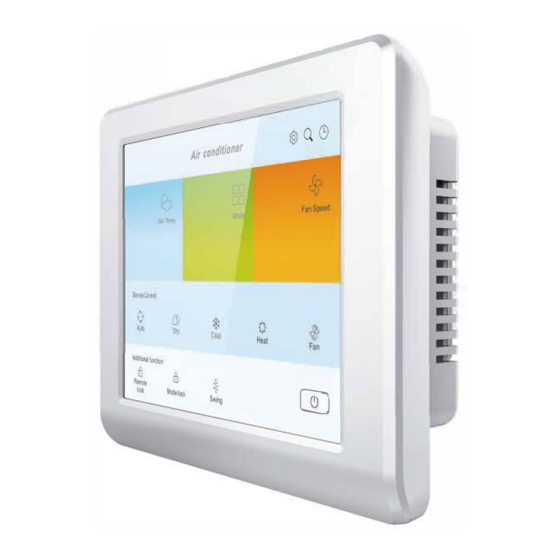
1. Resumen Este producto es compatible con productos de la gama VRV o conductos de alta presión, y es posible controlarla mediante su pantalla táctil o la app móvil. Además, también puede usar el software para monitorizar las unidades interiores mediante RTU. 2. - Page 4 2.2. lnstalación 2.2.1 Instalación encastrada 1. Deje un hueco en la pared (AnxAlxFo: 195mm x 135mm x 37mm) e instale una caja metálica como en la imagen; 2. Instale la cubierta trasera según la siguiente imagen; 3. Cuelgue el mando de control centralizado de los soportes de la cubierta trasera para encajarlo en la caja metálica.
- Page 5 2.2.2 Instalación mural 1) Coloque y fije la cubierta trasera en la pared. 2) Cuelgue el mando de los soportes de la cubierta trasera. © Air con { oner □□ □□ Set Temp Fan Speed Mode Device Control ,.._ ◊ (í) ..., Auto...
-
Page 6: Parámetros Técnicos Yconexión Del Cableado
3. Parámetros técnicos y conexión de cableado Descripción de la interfaz: Interfaz Descripción 110/220V, 50HZ/60HZ CA Alimentación (LN) Conecte al puerto XYE de la ud. exterior Puerto XYE Conecte al ordenador según protocolo Modbus Puerto ABE Conecte el terminal XYE al XYE de la unidad exterior y dé corriente a la unidad. -
Page 7: Funcionamiento
4. Funcionamiento 4.1. Ajuste de parámetros ◄ ModbusAddr: WIFI Configuration: lndoor units Rename: 1) El botón LAN sirve para conectar por WIFI LAN, y el botón Internet para para realizar la configuración remota. 2) Si renombra la unidad, debe reiniciar el control centralizado (desconectándolo de la corriente y volviéndolo a conectar). -
Page 8: Control De Parámetros
4.2. Control de parámetros 4.2.1 Ajuste de temperatura Sel Temp. Fan Speed Mode Devlce Control º Addilional function �- --� Remole Swing Mode lock lock 4.2.2 Modo ajuste Set Temp. Fan Speed Moda . � � Device Control � ,.,... ➔... - Page 9 4.2.3 Control de velocidad del ventilador Temp. Fan Speed Mode Device Control ;;� Auto Medfum spee High speed AddUional fiunclion Remote Swing Mode lock lock 4.2.4 Control del modo swing Temp. Fan Speed Mode Device Control Lowspeed Auto Medfum speed High speed AddHional f1unclion...
- Page 10 4.2.5 Bloqueo del control remoto Temp. Fan Speed Mode Device Control ;;� Auto Medfum speed High speed AddUional fiunclion Remote Swing Mode lock lock 4.2.6 Bloqueo de modo Temp. Fan Speed Mode Device Control Lowspeed Auto Medfum speed High speed AddHional f1unclion Remote Swing...
- Page 11 4.2.7 Encendido y apagado de la unidad interior Temp. Fan Speed Mode Device Control ;;� Auto Medfum speed High speed AddUional fiunclion Remote Swing Mode lock lock 4.2.8 Ajuste del temporizador semanal Temp. Fan Speed Mode Device Control Lowspeed Auto Medfum speed High speed...
- Page 12 Timer Timer Repeat Mode Speed Temp. Swing Status S un Mon. Tues. Wed. Thur. Fri. Sat. En esta pantalla puede configurar los parámetros del temporizador semanal, tanto de encendido (Timer ON) como de apagado (Timer OFF).
-
Page 13: Comprobación De Parámetros
4.3. Comprobación de parámetros Fan Speed Temp. Mode Device Control , ;, i Lowspeed Auto Medlum speed High speed Addltional function � Remole Swing Mode lock lock lndoor unit a.ddress: Error Capacity: Evaporator middle temp: Evaporator outlet temp:... -
Page 14: Función De Control De Grupo
4.4. Función de control de grupo 4.4.1 lntroducción > ◄ Set Temp. Mode FanSpeed Devlce Control 32'C 16*C Addltlona l function Remote Swing Mode lock lock... - Page 15 1) El botón "Name" (Nombre) sirve para configurar el nombre del primer grupo. Pueden configurarse un total de 4 grupos, de los cuales el primero sería el predeterminado. 2) Escoja el primer grupo de unidades interiores. 3) Si necesita configurar otro grupo, pulse el botón "Group number"...
- Page 16 4.4.2 Control de grupo Set Temp Mode Fan Speed Davice Control 16"C 32 e Addllional function Remole Swing Mode lock lock 1) Toque la barra superior de la pantalla "Group" para cam- biar a otro grupo. 2) El resto de ajuste de parámetros son iguales que si se realiza el control de una única unidad.
- Page 17 Anexo 1: Configuración del módulo WIFI 1. Descargue la APP Android Download "SMANAGER" On App Store...
- Page 18 2. Requisitos 2.1 Un punto WiFi con acceso a internet; 2.2 Un teléfono con Android 7.0 o más, con la app instalada; 2.3 Que el control centralizado pueda comunicar con la unidad exterior correctamente. 2. Conexión y uso 3.1 Configuración de red y añadir dispositivos 3.1.1 Mantenga pulsado el botón SW2 de la parte trasera del dispositivo durante 6 segundos hasta que la luz OL parpadee rápido.
- Page 19 3.1.4 Tras iniciar sesión, pulse en "Device Management" (Gestionar dispositivos) y luego pulse "Add" en la esquina superior izquierda para acceder a la configuración de red del dispositivo. 3.1.5 Introduzca el nombre y la contraseña del WiFi al que esté conectado el teléfono con el que está...
- Page 20 3.1.6 Espere a que se complete la configuración de red.
- Page 21 3.1.7 Cuando la configuración de red termine, la app mostrará un mensaje pop-up. Pulse OK para acceder a la interfaz información dispositivo. Al terminar el proceso el controlador se mostrará en línea, la luz OL parpadeará una vez cada 5 segundos y el servidor se conectará.
- Page 22 3.1.8 Los campos marcados con * delante del nombre son campos obligatorios. AC unit name (Nombre del dispositivo): Es aconsejable llamarlo según su situación real para ubicarlo fácilmente (p.ej. edificio de oficinas) * Series number (Número de serie): Introduzca el número de serie de la unidad interior o exterior.
- Page 23 3.2 Instrucciones de función La app S-manager cuenta con funciones como resumen de funcionamiento (reservado), monitorización de unidades, control de unidades interiores, centro personal (reservado). 3.2.1 Gestión de dispositivos Puede seleccionar esta función para mostrar todos controladores asociados con la cuenta actual o mostrar un único controlador mediante el menú...
- Page 24 Pulse en "IDU" para extender la lista de unidades interiores. Esta lista muestra el nombre de la unidad interior, su estado de funcionamiento, si hay fallos o está fuera de línea, temporizador, estado de bloqueo y temperatura de consigna. Mantenga pulsado el icono para las funciones de control remoto, datos de funcionamiento (reservado) y renombrar.
- Page 25 PD: La versión V1.0 de la lista de máquinas externas está reservada y no tiene funciones relacionadas por el momento. 3.2.2 Control de unidades interiores Pulse "choose" (seleccionar) en la esquina superior izquierda para cambiar la unidad interior que desea controlar. Pulse "Group Control"...
- Page 26 En el estado ON, pulse "Mode" para cambiar el modo de funcionamiento. Los modos pueden cambiarse entre refrigeración, calefacción, deshumidificación y ventilación. Pulse "fan speed" (velocidad del ventilador) para cambiar entre alta, media y baja. Pulse "Swing Up and Down" (swing vertical) y "Swing Left and Right"...
- Page 27 Tras enviar el comando de control, la interfaz mostrará “Sending” (enviando). recibido, mostrará “Success” (Correcto). Sending Success...
- Page 28 Pulse “Lock” (Bloqueo) para acceder a los ajustes de la función de bloqueo. En esta interfaz de ajustes, pulse a la derecha del nombre de la unidad interior y seleccione si desea activar o desactivar la función de bloqueo. "Available time" sirve para seleccionar el periodo de tiempo durante el cual será...
- Page 29 Pulse “Timer” para acceder a los ajustes de la función de temporizador. Puede ver los temporizadores que ya haya configurados en esta interfaz, y pulsarlos para editarlos. Pulse a la derecha para activar o desactivar cada temporizador. Pulse "+" en la esquina superior derecha para crear un nuevo temporizador.
-
Page 30: Protocolo De Comunicación Modbus
Protocolo de comunicación Modbus del control centralizado táctil ECG145CM General A. Use el protocolo modbus de tipo RTU. B. Use una estructura de transmisión maestra-esclava multipunto R485, modo semidúplex asíncrono, con longitud de datos de 8 bits sin paridad y una tasa de baudios de 9600bps. - Page 31 Modo refrig. 1: Válido; 0: Inválido Modo Auto 1: Válido; 0: Inválido Reservado Reservado, 0 Reservado Reservado, 0 ON/OFF 1=ON,0=OFF 1: Válido; 0: Inválido Veloc. Ventilad. alta 1: Válido; 0: Inválido Veloc. Ventilad. Med. 1: Válido; 0: Inválido Veloc. Ventilad. baja 1: Válido;...
- Page 32 detección cero E7 Error EEPROM 1: Error; 0: Normal E8 Error motor 1: Error; 0: Normal ventilador E9 Error mando 1: Error; 0: Normal por cable EA Fallo de 1: Error; 0: Normal sobrecorriente del compresor (4 veces) EB protección 1: Error;...
- Page 33 excesiva o insuficiente 1: Error; 0: Normal sobrecorriente del compresor Reservado, 0 Reservado, 0 Reservado, 0 Reservado, 0 Reservado, 0 Reservado, 0 PF, otra 1: Error; 0: Normal protección 0x40--0x4F Estado coil 4 Fallo de 1: Error; 0: Normal comunicación entre la interfaz y la PCB principal Fallo de...
- Page 34 Reservado Reservado, 0 Reservado Reservado, 0 Reservado Reservado, 0 Reservado Reservado, 0 Reservado Reservado, 0 Reservado Reservado, 0 Reservado Reservado, 0 Unidad interior 1# 0x50—0x5F Estado Coil 0 Igual que unidad interior 0# 0x60—0x6F Estado Coil 1 Igual que unidad interior 0# 0x70—0x7F Estado Coil 2 Igual que unidad interior 0#...
- Page 35 unidad interior unidad interior #1 unidad interior #9 en línea 0 unidad interior #2 unidad interior #10 unidad interior #3 unidad interior #11 unidad interior #4 unidad interior #12 unidad interior #5 unidad interior #13 unidad interior #6 unidad interior #14 unidad interior #7 unidad interior #15 1-Online;...
- Page 36 unidad interior #4 unidad interior #12 unidad interior #5 unidad interior #13 unidad interior #6 unidad interior #14 unidad interior #7 unidad interior #15 1-On; 0-Off unidad interior #16 unidad interior #24 unidad interior #17 unidad interior #25 unidad interior #18 unidad interior #26 unidad interior #19 unidad interior #27...
- Page 37 1-fallo; 0-normal unidad interior #16 unidad interior #24 unidad interior #17 unidad interior #25 unidad interior #18 unidad interior #26 unidad interior #19 unidad interior #27 Estado de fallo 0x22 unidad interior #20 unidad interior #28 ud. interior 1 unidad interior #21 unidad interior #29 unidad interior #22 unidad interior #30...
- Page 38 unidad interior 2 Modo ventilador 1: ON; Reservado 0: OFF Modo deshumidific. 1: Reservado ON; 0: OFF Modo calefacción 1: ON; Reservado 0: OFF Modo calefacc. 1: ON; 0: Modo de Reservado 0x02 funcionamiento Modo auto 1: ON; 0: OFF Reservado Reservado Reservado...
- Page 39 00: Bloqueo OFF o Reservado sin bloqueo 01: Bloqueo refrig. Reservado 10: Bloqueo calefac. 11: Bloqueo ventilad. Reservado Bloqueo de modo Modo DRY, 1: ON, 0: Bloqueo remoto E8 Error de motor E0 error de fase ventilador E1 Error de E9 Error mando por comunicación cable...
- Page 40 0x0D Consumo Unidad 0.1 HP Demanda de Demanda de capacidad real x10 0x0E capacidad de la unidad interior 0x0F—0x1F (Reservado) #01 Unidad interior Información de la 0x20 unidad interior 1 Información de la 0x21 unidad interior 2 Modo de 0x22 funcionamiento Velocidad 0x23...
- Page 41 n*0x20 + Velocidad del 0x03 ventilador n*0x20 + Temperatura de 0x04 consigna n*0x20 + Temperatura ud. 0x05 interior T1 n*0x20 + Temperatura 0x06 evaporador T2A Temperatura del n*0x20 + evaporador 0x07 medio T2B n*0x20 + Temporizador 0x08 encendido n*0x20 + Temporizador 0x09 apagado...
- Page 42 encendido Temporizador de 0x7E9 apagado Funciones de 0x7EA accesibilidad 0x7EB Código de error Código de 0x7EC protección 0x7ED Consumo Demanda de 0x7EE capacidad de la ud. interior 0x7EF– 0x7FF (Reservado) 1.5.3 Read/Write integer Parámetros de control (Código de función: escriba 0x06 o 0x10) Holding registers (Salidas analógicas) (W/R) Información de unidad interior única Dirección base: 0x3000;...
- Page 43 Velocidad baja 1: ON; 0: Reservado Velocidad brisa 1: ON; 0: Reservado Reservado Reservado Reservado Reservado Reservado Reservado Vent. AUTO 1: On; 0: Off Reservado Si todos los bits son 0 significa que el motor ventilador está apagado 0x02 Temperatura de 16~32 = 16~32℃;...
- Page 44 n*16 Modo de funcionamiento configurado n*16+1 Velocidad del ventilador n*16+2 Temperatura de consigna n*16+3 Temporizador de encendido n*16+4 Temporizador de apagado n*16+5 Funciones de accesibilidad n*16+6 -- n*16+15 Reservado #63 Unidad interior 0x3F0 Modo de funcionamiento configurado 0x3F1 Velocidad del ventilador 0x3F2 Temperatura de...
- Page 45 Reservado Reservado Reservado Reservado Interruptor ON/OFF; 1: Reservado ON; 0: OFF bit6~bit0 se excluyen mutuamente 0x91 Velocidad del Veloc. alta 1: ON; 0: OFF Reservado ventilador Veloc. media 1: ON; 0: Reservado Veloc. baja 1: ON; 0: OFF Reservado Veloc. brisa 1: ON; 0: Reservado Reservado Reservado...
- Page 46 Contents OVERVIEW PRODUCT APPEARANCE AND INSTALLATION Appearance Installation TECHNICAL PARAMETERS AND WIRING CONNECTION OPERATION Parameters setting Parameters controlling Parameters checking Group control function Modbus communication protocol...
-
Page 47: Overview
1. Overview This product is used for VRF and high pressure duct-type product, you can control it by touch screen or mobile phone APP. Moreover, you can also use host computer software to monitor indoor unit via RTU way. 2. Product appearance and installation 2.1. - Page 48 2.2. lnstallation 2.2.1 Embedded installation 1. Leaving a hole (Length xWidth x Height: 195mm x 135mm x 37mm) before house decoration, and install an iron box like picture below ; 2. After installing iron box, please install rear cover which like picture below;...
- Page 49 2.2.2 Showing installation 1) First install the rear cover, and fixed it on the wall. 2) Hang the touch screen centralized controller on rear cover. © Air con { oner □□ □□ Set Temp Fan Speed Mode Device Control ,.._ ◊...
-
Page 50: Technical Parameters And Wiring Connection
3. Technical parameters and wiring connection Interface description: Interface Description Power interface (LN) 110/220V, 50HZ/60HZ AC power XYE port Connect to outdoor unit XYE port Connect to host computer, Modbus protocol ABE port Connect XYE to XYE of outdoor unit, and Power On, lt will enter the control interface after 30 seconds. -
Page 51: Operation
4. Operation 4.1. Parameters setting ◄ ModbusAddr: WIFI Configuration: lndoor units Rename: 1) LAN button means connect to WIFI LAN, Internet button means connect to remote configuration. 2) lf you rename the unit, you should repower the controller. -
Page 52: Parameters Controlling
4.2. Parameters controlling 4.2.1 Setting temperature Sel Temp. Fan Speed Mode Devlce Control º Addilional function �- --� Remole Swing Mode lock lock 4.2.2 Setting mode Set Temp. Fan Speed Moda . � � Device Control � ,.,... ➔ • ,;;.,j' Auto Cool... - Page 53 4.2.3 Fan speed control Temp. Fan Speed Mode Device Control ;;� Auto Medfum spee High speed AddUional fiunclion Remote Swing Mode lock lock 4.2.4 Swing control Temp. Fan Speed Mode Device Control Lowspeed Auto Medfum speed High speed AddHional f1unclion Remote Swing Mode lock...
- Page 54 4.2.5 Remote control lock Temp. Fan Speed Mode Device Control ;;� Auto Medfum speed High speed AddUional fiunclion Remote Swing Mode lock lock 4.2.6 Mode lock Temp. Fan Speed Mode Device Control Lowspeed Auto Medfum speed High speed AddHional f1unclion Remote Swing Mode lock...
- Page 55 4.2.7 Power on/off the indoor unit Temp. Fan Speed Mode Device Control ;;� Auto Medfum speed High speed AddUional fiunclion Remote Swing Mode lock lock 4.2.8 Weekly time setting Temp. Fan Speed Mode Device Control Lowspeed Auto Medfum speed High speed AddHional f1unclion Remote...
- Page 56 Timer Timer Repeat Mode Speed Temp. Swing Status S un Mon. Tues. Wed. Thur. Fri. Sat.
-
Page 57: Parameters Checking
4.3. Parameters checking Fan Speed Temp. Mode Device Control , ;, i Lowspeed Auto Medlum speed High speed Addltional function � Remole Swing Mode lock lock lndoor unit a.ddress: Error Capacity: Evaporator middle temp: Evaporator outlet temp:... -
Page 58: Group Control Function
4.4. Group control function 4.4.1 lntroduction > ◄ Set Temp. Mode FanSpeed Devlce Control 32'C 16*C Addltlona l function Remote Swing Mode lock lock... - Page 59 1) Name button means set first group name (A total of four group can be set, the default group is first group). 2) Choosing first group indoor unit. 3) lf you need set other group, you can press group number button to create new group;...
- Page 60 4.4.2 Group control Set Temp Mode Fan Speed Davice Control 16"C 32 e Addllional function Remole Swing Mode lock lock 1) Press the group area to switch different group. 2) The other parameters setting is the same like single unit control.
- Page 61 Attachment 1: WIFI module configuration 1. Download the APP Android Download "SMANAGER" On App Store...
- Page 62 2. Preparations 2.1 A WiFi hotspot with internet access; 2.2 A phone with Android 7.0 or higher, installed with Smart APP; 2.3 Centralized controller can communicate with outdoor unit successfully. 3. Connection and use 3.1 Network configuration and device addition 3.1.1 Long press SW2 button for 6 seconds on the back of the controller until OL light flash quickly;...
- Page 63 3.1.4 After successful login, click to "Device Management" and then click "Add" in the upper left corner to enter the device network configuration. 3.1.5 Fill in the name and password of the WiFi connected to the current mobile phone, and then click "Next", to make the controller automatically connect to the WiFi.
- Page 64 3.1.6 Wait for the network configuration to complete.
- Page 65 3.1.7 After the network configuration is completed, the app gives a prompt message. Click OK to enter the device informa- tion interface. After the network configuration is completed, the controller goes online, the OL light flashes once every 5 seconds, and the server is successfully connected.
- Page 66 3.1.8 The fields with * in front of the column names are required. Device name: Fill in according to the actual situation, for remarks (e.g. office building) Serial number: Fill in the serial number of IDU or ODU. If there is no, you can fill in the MAC of current controller.
- Page 67 3.2 Function instruction S-manager APP is with operation overview (reserved), units monitoring, indoor units control, personal center (reserved) functions. 3.2.1 Device management You can choose to display all the controller associated with the current account or display a single designated controller through the top selection.
- Page 68 Click on IDU to expand the indoor unit list. The list can display the indoor unit name, running status, fault, offline, timing, lock status and setting temperature. Long press the icon for remote control, running data (reserved), rename operation. Click the name of the controller to expand the information of the controller.
- Page 69 PS: The version V1.0 of the external machine list is reserved and there is no related function for the time being. 3.2.2 Indoor unit control Click "choose" in the upper left corner to switch the indoor unit that needs to be controlled. Click "Group Control"...
- Page 70 In the ON state, click "Mode" to switch the running mode. The modes can be switched among cooling, heating, dehumidification, and ventilation. Click "fan speed" to switch from high, medium, low wind. Click " Swing Up and Down" and " Swing Left and Right" to turn on or off the corresponding swing.
- Page 71 After the control command is sent, the control interface prompts “Sending”. After the control command is received, it prompts “Success”. Sending Success...
- Page 72 Click “Lock” to enter the lock function setting. In the lock setting interface, click on the right side of the indoor unit name and select whether to enable or disable the lock function. Available time selects when the lock will take effect. The controller selects whether to enable the remote lock of the internal unit.
- Page 73 Click “Timer” to enter the timer function setting. You can view the existing timing on the timing interface. Click the timer to edit it again. Click on the right to enable or disable this timer. Click "+" at the top right of the timing control interface to create a new timing rule.
-
Page 74: Modbus Communication Protocol
ECG145CM Touch screen controller Modbus communication protocol Overview A. Use RTU type of ModBus protocol B. Use R485 multi point bus master-slave structure, asynchronous half duplex mode, The data length of 8 bits no parity, baud rate is 9600bps. (8,N,1 for RTU) 1.2 Character structure (8, N, 1) - Page 75 Cooling mode 1: Valid, 0: Invalid Auto mode 1: Valid, 0: Invalid Reserve Reserve, 0 Reserve Reserve, 0 ON/OFF 1=ON,0=OFF High fan speed 1: Valid, 0: Invalid Middle fan speed 1: Valid, 0: Invalid Low fan speed 1: Valid, 0: Invalid Breeze fan speed 1: Valid, 0: Invalid Reserve...
- Page 76 Zero 1: Error, 0: Normal detection error EEPROM 1: Error, 0: Normal error motor 1: Error, 0: Normal error Wired 1: Error, 0: Normal controller error EA compressor 1: Error, 0: Normal overcurrent error (4 times) inverter 1: Error, 0: Normal module protection EC error...
- Page 77 protection compressor 1: Error, 0: Normal overcurrent Reserve, 0 Reserve, 0 Reserve, 0 Reserve, 0 Reserve, 0 Reserve, 0 other 1: Error, 0: Normal protection 0x40--0x4F Coil status 4 Communication 1: Error, 0: Normal failure between network interface and main PCB Communication 1: Error, 0: Normal failure between...
- Page 78 Reserve Reserve, 0 Reserve Reserve, 0 Reserve Reserve, 0 Reserve Reserve, 0 1# Indoor unit 0x50—0x5F Coil status 0 Same with 0# indoor unit 0x60—0x6F Coil status 1 Same with 0# indoor unit 0x70—0x7F Coil status 2 Same with 0# indoor unit 0x80—0x8F Coil status 3 Same with 0# indoor unit...
- Page 79 #5 indoor unit #13 indoor unit #6 indoor unit #14 indoor unit #7 indoor unit #15 indoor unit 1-Online;0-Offline #16 indoor unit #24 indoor unit #17 indoor unit #25 indoor unit #18 indoor unit #26 indoor unit #19 indoor unit #27 indoor unit Indoor unit 0x02...
- Page 80 #16 indoor unit #24 indoor unit #17 indoor unit #25 indoor unit #18 indoor unit #26 indoor unit #19 indoor unit #27 indoor unit Indoor unit 0x12 #20 indoor unit #28 indoor unit running status 1 #21 indoor unit #29 indoor unit #22 indoor unit #30 indoor unit #23 indoor unit...
- Page 81 #20 indoor unit #28 indoor unit #21 indoor unit #29 indoor unit #22 indoor unit #30 indoor unit #23 indoor unit #31 indoor unit 1-failure;0-normal #32 indoor unit #40 indoor unit #33 indoor unit #41 indoor unit #34 indoor unit #42 indoor unit #35 indoor unit #43 indoor unit...
- Page 82 ON, 0: OFF Heating mode 1: ON, 0: Reserve Cooling mode 1: ON, 0: Reserve Auto mode 1: ON, 0: Reserve Reserve Reserve Reserve Reserve Switch ON/OFF, 1: ON, Reserve 0: OFF bit6~bit0 mutual exclusion each other High speed 1: ON, 0: Reserve Middle speed 1: ON, 0: Reserve...
- Page 83 lock 01: Lock cooling Reserve 10: Lock heating 11: Lock fan mode Reserve Mode lock DRY mode, 1:ON, 0:OFF Remote lock E0 phase error E8 Fan motor error Communication E9 Wired controller error error EA, compressor E2 T1 sensor error overcurrent error (4 times) EB, inverter module...
- Page 84 capacity demand 0x0F—0x1F (Reserve) #01 Indoor unit Indoor unit 0x20 information 1 Indoor unit 0x21 information 2 0x22 Running mode 0x23 Fan speed Setting 0x24 temperature Indoor unit 0x25 temperature T1 Evaporator 0x26 temperature T2A Temperature 0x27 middle evaporator T2B 0x28 Timer on 0x29...
- Page 85 0x06 temperature T2A Temperature n*0x20 + middle 0x07 evaporator T2B n*0x20 + Timer on 0x08 n*0x20 + Timer off 0x09 n*0x20 + Accessibility 0x0A functions n*0x20 + Error code 0x0B n*0x20 + Protection code 0x0C n*0x20 + Power 0x0D consumption n*0x20 + Indoor unit 0x0E...
- Page 86 Indoor unit 0x7EE capacity demand 0x7EF– 0x7FF (Reserve) 1.5.3、 【 Read/Write integer】 Control parameters ( Operation function code: write 0x06 or 0x10) Holding registers (W/R) Singe indoor unit info Base address: 0x3000, Max. amount of data of each module: 16 bytes Operation address = Base address + Relative address Relative Data name...
- Page 87 temperature 0x03 Timer on ---(Invalid) 0x04 Timer off ---(Invalid) 0x05 Accessibility Economic operation Reserve functions 1:on, 0:off Auxiliary heater Reserve 1:on, 0:off Swing 1: On, 0: Off Reserve Reserve Reserve Reserve Reserve Reserve Reserve Reserve Reserve Reserve Reserve 0x06—0x0F (Reserve) #01 Indoor unit 0x10 running...
- Page 88 speed 0x3F2 Setting temperature 0x3F3 Timer on 0x3F4 Timer off 0x3F5 Accessibility functions 03F6--0x3FF (Reserve) Group control info Base address: 0x2000, Max. amount of data of each module: 16 bytes Operation address = Base address + Relative address Relative Data name Note addr.
- Page 89 0x93 Timer on ---(Invalid) 0x94 Timer off ---(Invalid) 0x95 Accessibility Economic operation Reserve functions 1:on, 0:off Auxiliary heater Reserve 1:on, 0:off Swing 1: On, 0: Off Reserve Reserve Reserve Reserve Reserve Reserve Reserve Reserve Reserve Reserve Reserve 0x96--0x9F (RESERVED)
- Page 90 Toda la documentación del producto Complete documents about the product Documentation plus complète sur le produit Mais documentação do produto EAS ELECTRIC SMART TECHNOLOGY, S.L.U. P.I. San Carlos, Camino de la Sierra, S/N, Parcela 11 03370 Redován (Alicante) - ESPAÑA...
Need help?
Do you have a question about the ECG145CM and is the answer not in the manual?
Questions and answers