Table of Contents
Advertisement
Advertisement
Table of Contents

Related Manuals for Consilium Salwico GD


Summary of Contents for Consilium Salwico GD
- Page 1 Technical Manual Salwico GD Gas Detector...
-
Page 2: Safety
“Seal Fitting” installed for each of the cable gland entries within 18 inches of the Salwico GD. The total distance of the location of these Seal Fittings is 18 inches. (e.g. If all 3 gland entries are to be used, 3 Seal Fittings should be located, each within 6 inches of the wiring entrance). - Page 3 22 mA: Over range 7. If the Salwico GD is operating in conjunction with a control unit to analyse the measuring signal, the control unit must operate correctly when the Salwico GD transmits a value outside of the measuring range.
- Page 4 22 mA: Over ranging 7. If the Salwico GD is operating in conjunction with a control unit to analyse the measuring signal, the control unit must operate correctly when the Salwico GD transmits a value outside of the measuring range.
-
Page 5: Information
This manual is for use with the Salwico GD range transmitters only. The Start-up/Surge/In rush current is dependant on the type of power supply used. The typical start-up current for Salwico GD is less than 800mA. Measure the start-up current using the specific power supply before installation to ensure suitability for your application. -
Page 6: Table Of Contents
Salwico GD Technical Manual 5100516-00A Rev:A01 3 Table of contents 1 Safety 2 Information 3 Table of contents 4 Introduction 4.1 Transmitter 4.2 Flammable, Toxic Oxygen Gas sensors 4.3 Accessories 5 Installation 5.1 Mounting and location 5.2 Mounting the transmitter 5.3 Installing the sensor... - Page 7 17.2 Salwico GD ATEX Name Plate 17.3 Sensor Cartridges Label 18 EC Declaration of Conformity 19 Cross Interference and Cross Calibration 19.1 Cross Interference Table for Toxic and Oxygen 19.2 Cross Calibration Flammable Gas Detector 19.3 Meter Multiplication Factors for Salwico GD-IR Propane...
-
Page 8: Introduction
Calibration and maintenance is carried out using a Magnetic Wand, this allows a single user to undertake routine maintenance without needing to access internal components. Salwico GD is suitable for use in Zone 1 or 2 hazardous areas (International) or Class I Division 1 or 2 area applications (North America). -
Page 9: Transmitter
Salwico GD sensors use NDIR infrared and electro-catalytic technologies. In addition, the Salwico GD transmitter is designed to work with a wide range of toxic gas sensors. Salwico GD sensors for monitoring toxic gas or oxygen use electro-chemical cell (ECC) technology. Oxygen sensors measure Oxygen deficiency and... -
Page 10: Accessories
5100516-00A Rev:A01 Diagram 3: Salwico GD Flammable, Toxic and Oxygen Sensor Cartridge 4.3 Accessories A range of accessories are available to allow use of Salwico GD in a wide variety of applications. These including mounting brackets, maintenance tools, weather housings, flow housing, collecting cone, duct mounting kit and sensor junction boxes. -
Page 11: Installation
5100516-00A Rev:A01 5 Installation WARNINGS Salwico GD is designed for installation and use in Zone 1 or 2 hazardous areas in many countries including Europe and for Class 1 Division 1 or 2 area applications in North America. Installation must be in accordance with the recognized standards of the appropriate authority in the country concerned. -
Page 12: Mounting And Location
5.2 Mounting the transmitter The Salwico GD transmitter has an integral mounting plate consisting of four mounting holes on the transmitter body. The transmitter may be fixed directly to a surface mounting, or to a horizontal or vertical pipe/structure, 40.0-80.0mm (1.6 to 3.1 inches) in diameter/ cross section. -
Page 13: Installing The Sensor
Diagram 6: Installing the Sensor WARNINGS Care should be taken when removing and refitting the Salwico GD plug-in Sensor to the Sensor Socket so that damage to the connection pins can be avoided. If using an anti-seize compound, the threads should be thinly coated with an approved silicone free compound e.g. -
Page 14: Electrical Connections
Electrical connections WARNINGS Salwico GD is designed for installation and use in Zone 1 or 2 hazardous areas in many countries including Europe and Class 1 Division 1 or 2 area applications in North America. Installation must be in accordance with the recognized standards of the appropriate authority in the country concerned. -
Page 15: Transmitter Wiring
Caution: All electrical connections should be made in accordance with any relevant local or national legislation, standards or codes of practice. The Salwico GD transmitter may be wired in either Current SOURCE or Current SINK configuration. These two options are offered to allow greater flexibility in the type of control system that it can be used with. SOURCE/SINK is selectable via the switch located on the back side of the display module;... -
Page 16: Terminal Connections
Salwico GD Technical Manual 5100516-00A Rev:A01 6.2 Terminal connections Note: Ensure that none of the wires in the terminal area cause an obstruction when refitting the Display Module. Ensure that the socket on the Display Module is fully engaged in the Display Module Connector on the Terminal Module. -
Page 17: Power
5100516-00A Rev:A01 6.3 Power The Salwico GD transmitter requires a power supply from the controller of between 16Vdc and 32Vdc. Ensure that a minimum supply of 16Vdc is measured at the sensor, taking into account the voltage drop due to cable resistance. -
Page 18: Cabling
Salwico GD Technical Manual 5100516-00A Rev:A01 6.4 Cabling Caution: All unused and used cable/conduit entries must be sealed with a suitable certified sealing plug and cable gland. The use of industrial grade, suitably armoured field cable is recommended. For example, screened 3 cores (plus screen 90% coverage), suitably mechanically protected copper cable with a suitable M20 explosion-proof gland, or ¾” NPT steel conduit, with 0.5 to 2.5 mm2 (20 to 13 AWG) conductors. -
Page 19: Ground Terminal Wiring
Salwico GD Technical Manual 5100516-00A Rev:A01 The Earth Screen of the field cable should be “tied to Earth” or connected to Ground at one point only. It is common practise to adopt a STAR EARTH connection regime where all instrumentation Screens are connected at one common point. The Screen at the other end of the cable should be “parked” or terminated into a blank terminal. -
Page 20: Default Configuration
Rising Flammable IR 100%LEL 20%LEL Rising 40%LEL Rising Flammable CAT 100%LEL 20%LEL Rising 40%LEL Rising Carbon Dioxide IR 2.00%Vol 0.40%Vol Rising 0.80%Vol Rising For details of how to change the configuration of the Salwico GD please refer to section 13. -
Page 21: Normal Operation
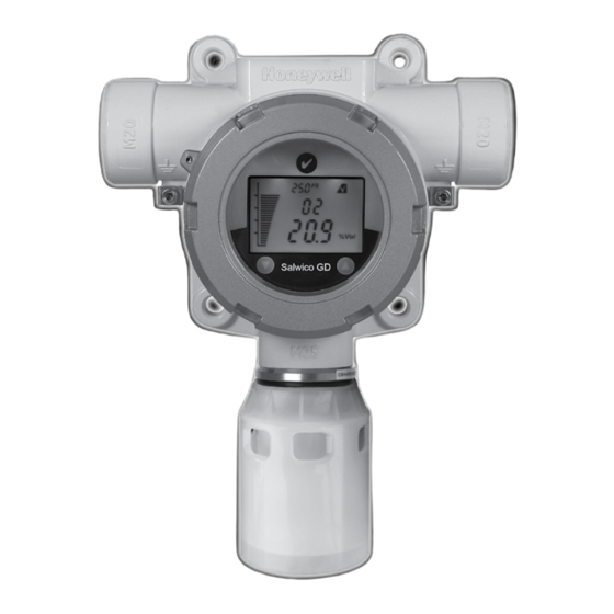
Access to the Salwico GD transmitter’s configuration menus system is via the Magnetic Activation Tool. 8.1 Display Screen The Salwico GD display features an LCD with Numeric and bar-graph gas concentration data, alpha-numeric warning and status indication, a target for magnetic switch activation and the UP/DOWN/ESC/ENTER zones for remote configuration. The LCD is also backlit with hi-intensity multi-colour LED indicator to show NORMAL, ALARM and FAULT status. -
Page 22: System Status
Salwico GD Technical Manual 5100516-00A Rev:A01 8.2 System Status Display indications, current output and relay states for various operational conditions are shown in the following table. For further details of error messages and trouble shooting see section 12.3. System Status... -
Page 23: Magnetic Wand Activation
Hold the Magnetic Wand in position for 3 seconds or more 8.4 Mode Struc Salwico GD has 3 operating modes. 1. Monitoring mode, is the normal operating status while Salwico GD measures and displays gas concentration. The fault/warning status is periodically checked, relay contacts are activated according to the configuration. -
Page 24: First Time Switch On (Commissioning)
Salwico GD Technical Manual 5100516-00A Rev:A01 9 First time switch on (Commissioning) WARNING The following procedure requires the Transmitter Cover to be removed while carrying out supply voltage checks. Therefore the appropriate permits to work should be sought in preparation. - Page 25 Salwico GD Technical Manual 5100516-00A Rev:A01 Note: For a full description of each screen shown in Diagram 15., please refer to Section 13.3 “Review Mode” of this Manual. Diagram 15: Normal Start up procedure (For the CO sensor version) 11.The warm up countdown of 60 seconds (depending on the gas type) is then displayed.
-
Page 26: Response Check And Calibration
5100516-00A Rev:A01 10 Response Check and Calibration It is recommended to periodically carry out a gas response check on the Salwico GD to ensure correct operation. This may be done in two ways; 1. A simple Response Check often referred to as a “BUMP TEST” is a test using calibration gas applied to the sensor via the nozzle of the Weather Protection or using the Salwico GD Gassing Cap. - Page 27 Salwico GD Technical Manual 5100516-00A Rev:A01 To calibrate the detector follow the procedure below. Note: the Oxygen sensor does not require a zeroing procedure. Background air (20.9%Vol oxygen) can be used to span the oxygen sensor in place of a compressed air cylinder (20.9%Vol oxygen).
- Page 28 13. Connect the regulator to the span gas cylinder. 14. Apply the span gas to the sensor using the Salwico GD Gassing Cap (see section 4.7 for description). The live gas reading is displayed. When the reading is stable, use ‘...
- Page 29 18. The display alternates between “Purg gAS” and the gas reading to indicate that the unit is expecting the span gas to be removed from the sensor. 19. Promptly switch off the calibration span gas and remove the Salwico GD Gassing Cap from the sensor to allow the gas to disperse.
-
Page 30: Zeroing And Span Calibration Of Hydrogen Sulfide Sensors
Salwico GD Technical Manual 5100516-00A Rev:A01 10.2 Zeroing and span calibration of Hydrogen Sulfide sensors Hydrogen Sulphide sensors can be affected by extreme humidity changes. A sudden increase in ambient humidity can result in a short-term positive drift in the instrument’s reading. -
Page 31: General Maintenance
Access to the interior of the transmitter, when carrying out any work, must only be conducted by trained personnel. Care should be taken when removing and refitting the Salwico GD plug-in Sensor Cartridge to the Sensor Socket so that damage to the connection pins can be avoided. -
Page 32: Servicing
Do not expose sensor to organic solvents or flammable liquids. Care should be taken when removing and refitting the Salwico GD plug-in Sensor Cartridge to the Sensor Socket so that damage to the connection pins can be avoided. - Page 33 Locking Grub Screw Diagram 13: Sensor Replacement To replace the plug-in sensor of a Salwico GD Sensor Socket use the following procedure: 1. Important: Remove the Power from the Salwico GD Transmitter 2. Remove the Weather Protection or other accessories from the sensor socket thread.
-
Page 34: Replacing Modules Within The Transmitter
Module. 3. Unplug the connection terminals and lift them clear of the Terminal Module. 4. Unplug the connector for the Salwico GD sensor. 5. Loosen and remove the three “cross-headed” screws that secure the Terminal Module to the Transmitter housing. -
Page 35: Faults And Warnings
Salwico GD Technical Manual 5100516-00A Rev:A01 12.3 Faults and Warnings The table below provides details of possible error. Message Description Action The unit has not been calibrated for the configured calibration interval W-01 Calibration needed Calibration is necessary due to change of sensor/gas type... -
Page 36: Menu's And Advanced Configuration
Salwico GD Technical Manual 5100516-00A Rev:A01 13 Menu’s and Advanced Configuration 13.1 Abort Function In Review Mode or Configuration Mode the user can escape one step back from the current position using the Abort Function. To do this the user must activate the Enter switch for more than 3 seconds with the Magnetic Wand. - Page 37 Salwico GD Technical Manual 5100516-00A Rev:A01 Menu Display Description Execute zero/span calibration Set calibration gas level Set Calibration After zero, the option exists to proceed with span calibration, or return to the Menu. Select the type of sensor from the sensor list. This Select Sensor menu is only available for flammable / IR sensor.
- Page 38 Salwico GD Technical Manual 5100516-00A Rev:A01 Set Location Set location (or TAG number) Set Temperature Change temperature display unit. Unit °C (Celcius) or °F (Fahrenheit) Check Alarm Simulate alarm situation to check the alarm system functions without gas present at the sensor...
-
Page 39: Configuration Mode Operation Table
Salwico GD Technical Manual 5100516-00A Rev:A01... - Page 40 Salwico GD Technical Manual 5100516-00A Rev:A01...
-
Page 41: Sensor / Gas Selection
Ir-4 sensor is attached, then gas type is detected by Salwico GD automatically like CO mEt/ProP gas.. But when Cb-1 sensor is attached to the Salwico GD, a user can select the gas from Str1 (1*) to Str8 (8*). For more information on star rating, please refer to section 19.2. - Page 42 Salwico GD Technical Manual 5100516-00A Rev:A01 Diagram 16: Gas Selection...
-
Page 43: Review Mode
Salwico GD Technical Manual 5100516-00A Rev:A01 13.4 Review Mode The instrument will enter Review mode when the “Enter” switch is activated with the Magnetic Wand and held for around one second. Names, displays and descriptions for each review item in Review Mode are shown in the following table. - Page 44 Salwico GD Technical Manual 5100516-00A Rev:A01 Location Location in which the transmitter is installed Power Power voltage* Temperature Internal Transmitter temperature* Peak conc. Maximum concentration detected up to now Test Result There is no fault detected. Table 8: Transmitter menu descriptions...
- Page 45 Salwico GD Technical Manual 5100516-00A Rev:A01 Menu Switch (1s to 3s) Review Monitoring Mode Mode Abort Auto end to cycle S/W Version Test Result 2 second delay 2 second delay SRS Version Peak Reading 2 second delay 2 second delay...
-
Page 46: General Specification
Salwico GD Technical Manual 5100516-00A Rev:A01 14 General specification Salwico GD Transmitter. 3-wire, 4-20mA, gas detector transmitter for use with directly installed flammable and toxic gas sensors. For the protection of personnel and plant from flammable and toxic gas hazards. Electrical Input Voltage Range: 16 to 32Vdc (24Vdc nominal) Max Power Consumption: Max 5 Watts. at 24Vdc (see section 2 regarding maximum in rush current) Current output 4-20mA (Source or Sink) ≥0.0<1.0 mA... - Page 47 Long term operation at this range may cause decline in sensor performance. ** Care should be taken when setting alarm points lower than 3ppm especially in high humidity conditions (higher than 50%RH), since the gas reading could be lower than the actual concentration. Contact Consilium for any additional data or details.
-
Page 48: Warranty Statement
Salwico GD Technical Manual 5100516-00A Rev:A01 15 Warranty statement All Consilium gas detectors are warranted by Consilium Marine & Safety AB to be free from defects in material or workmanship under normal use and service for the following period: Fixed gas detectors... -
Page 49: Installation Drawing
Salwico GD Technical Manual 5100516-00A Rev:A01 16 Installation Drawing 16.1 Mechanical Installation Drawing... -
Page 50: Collecting Cone Drawing
Salwico GD Technical Manual 5100516-00A Rev:A01 16.2 Collecting Cone Drawing... -
Page 51: Mounting Bolt Assy Drawing
Salwico GD Technical Manual 5100516-00A Rev:A01 16.3 Mounting Bolt Assy Drawing... -
Page 52: Mounting Bracket Drawing
Salwico GD Technical Manual 5100516-00A Rev:A01 16.4 Mounting Bracket Drawing... -
Page 53: Certification
Salwico GD Technical Manual 5100516-00A Rev:A01 17 Certification 17.1 ATEX Special Conditions for Safe Use Sensor: The integral supply cable is to be protected from impact and be suitably terminated. The attachment thread has a 3mm wide undercut. This shall be taken into consideration if the sensor is attached to a flameproof enclosure in order to maintain the minimum engaged thread length. -
Page 54: Salwico Gd Atex Name Plate
Salwico GD Technical Manual 5100516-00A Rev:A01 17.2 Salwico GD ATEX Name Plate... -
Page 55: Sensor Cartridges Label
Salwico GD Technical Manual 5100516-00A Rev:A01 17.3 Sensor Cartridges Label... -
Page 56: Ec Declaration Of Conformity
Salwico GD Technical Manual 5100516-00A Rev:A01 18 EC Declaration of Conformity A full EC declaration of conformity can be found accompanying the product. This document lists the European Standards with which the Salwico GD complies. -
Page 57: Cross Interference And Cross Calibration
19 Cross Interference and Cross Calibration 19.1 Cross Interference Table for Toxic and Oxygen This below table shows the relative cross sensitivity of the Salwico GD to other gases. “Gas Type” indicated the Salwico GD sensor type fitted to the Salwico GD. “Gas Type Applied” indicates the gas that may be applied to that sensor and the resulting Reading. -
Page 58: Cross Calibration Flammable Gas Detector
“cross calibration” using another hydrocarbon gas/air mixture. When the Salwico GD Combustible LEL sensor is to be calibrated with a gas which is different to the gas or vapour to be detected, the following cross calibration procedure may be followed: Caution: Where the user calibrates any sensor using a different gas, responsibility for identifying and recording calibration rests with the user. - Page 59 Salwico GD Technical Manual 5100516-00A Rev:A01 Propan-2-ol Styrene Tetra hydrafuran Toluene Triethylamine Xylene Table 14 . Star Rating of Gases To cross calibrate the Salwico GD flammable gas detector: (1) Obtain the star rating for both the calibration test gas and the gas to be detected from Table 14 (2) These values may then be used in Table 15 to obtain the required calibration span setting when a 50% LEL test gas is applied to the detector.
- Page 60 Salwico GD Technical Manual 5100516-00A Rev:A01 Table 16. Correction factors Notes: 1. Since catalytic sensors require oxygen for correct operation, a mixture of gas in air should always be used for calibration purposes. 2. Assuming average performance of the sensor, the sensitivity information in Tables 14 To 16 is normally accurate to + or - 30%.
-
Page 61: Meter Multiplication Factors For Salwico Gd-Ir Propane
NOTE Consilium recommends that users verify the accuracy of their instruments using test gasses wherever possible. Cross-referred measurements should be used as a guide only, not as absolute values. - Page 62 Oman Singapore Sales- and Service Representatives Consilium is constantly increasing and improving its global sales and service organisation in order to provide our customers with the most competent service and support. Today Consilium has established own companies in i r t...
Need help?
Do you have a question about the Salwico GD and is the answer not in the manual?
Questions and answers