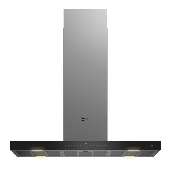
Summary of Contents for Beko BHCI98841BBHSI
- Page 1 Montaj Talimatları Installation Instructions Installationsanleitung Instructions d’installation Installatie instructies TR / EN / DE / FR / NL 185.7324.94/R.AA/16.01.2023...
- Page 2 Ø 3,5 x 22 mm...
- Page 3 280,8 21,4 min: 915,5 max: 1365,5 min.650 min.650...
-
Page 4: Top View
TOP VİEW... - Page 8 R 150 mm R 120 mm...
- Page 10 TR - Güvenlik talimatları Ürünün kurulumu • Garantinin geçerliliğini kaybetmemesi için, Ürününüz baca tipine göre 2 farklı şekilde ürünün yetkili bir kişi tarafından geçerli kurulum yapılabilir. Evinize uygun kurulumu yönetmeliklere göre kurulması gerekir. belirleyerek takip eden kurulum adımlarını Yetkili olmayan kişiler tarafından yapılan izleyebilirsiniz.
- Page 11 • Ürününüz fişli ise kurulum sırasında fişi • Alt baca sacını da iskeletin alt kısmında keserek elektrik bağlantısı yapmayın. geçirin. Düşmemesi için baca altından Kesilerek yapılan bağlantılarda ürün iskelet üzerindeki deliklere 2 adet vidayı garantisi geçersiz olur ve kullanıcı güvenliği geçici vidalayın.(Resim13) açısından tehlike oluşturur.
- Page 12 • Ürünle birlikte verilen şablon kurulum • Baca çıkış borunuzun çapı 150 mm ise, kağıdınızın merkez noktasını tavanda baca çıkış borusunu kapağın üzerine işaretlediğiniz noktaya yerleştirin. Verilen yerleştirin.(Resim 15) şablonu “Front” yazan kısmın ocağınızın • Baca çıkış borunuzun çapı 120 mm ise; ön tarafına gelecek şekilde ve ocağınızın kapağın üzerine baca bağlantı...
-
Page 13: Installation Of The Appliance
EN - Safety Instructions Installation of the appliance • The appliance shall be installed by a Installation can be made in 2 different ways qualified person in accordance with the according to the flue type of your product. regulations in force to keep the warranty You can determine the installation method applicable. - Page 14 • Install your appliance in a way that the • Insert the upper flue sheet in the lower electrical connection (power outlet, plug) part of the frame and fix it temporarily with can be easily reached after installation. 2 screws as shown in Figure 12. •...
-
Page 15: Installation Of Carbon Filter
• Determine the centre point of your hob. shown in Figure 14. Fix the hood to the Identify and mark the centre point of frame with 4 screws. the trace drop on the ceiling at the exact • Place the cover that prevents reverse air alignment of the centre point. -
Page 16: Installation Des Geräts
DE- Sicherheitshinweise nicht für Geräte, die Luft in den Raum zurückführen). • Das Gerät muss von einer qualifizierten • Die Vorschriften zur Luftabsaugung sind Person in Übereinstimmung mit den einzuhalten. geltenden Vorschriften installiert werden, • Wenn die Aluminiumfilter (Öl) nicht damit die Garantie gültig bleibt. - Page 17 angeschlossen werden. Lassen Sie Rahmen, wie in Abbildung 4a dargestellt. die elektrischen Anschluss von einem • Befestigen Sie die Dübel an der Decke, qualifizierten Elektriker durchführen. indem Sie an den 4 markierten Stellen • Trennen Sie das Gerät vom elektrischen bohren.
- Page 18 • Isolieren Sie die Verbindungsstellen mit einem Bleistift an der Decke, wie in entsprechend. Abbildung 3 dargestellt. • Entfernen Sie die 2 Schrauben, die das • Um die Luftleitplastik zu installieren, untere Abgasblech vorübergehend halten, entfernen Sie die 8 Schrauben am oberen und senken Sie es in den Haubenkörper Trägerrahmen (Abbildung 4b) und nehmen Sie das Deckenanschlussblech ab.
-
Page 19: Fr - Consignes De Sécurité
FR - Consignes de sécurité umgekehrten Luftstrom verhindert, wie in Abbildung 15 dargestellt am Rauchabzug • L’appareil doit être installé par une personne qualifiée conformément à la • Wenn der Durchmesser Ihres réglementation en vigueur pour que la Rauchabzugsrohrs 150 mm beträgt, garantie reste applicable. -
Page 20: Installation De L'appareil
Installation de l’appareil responsable des dommages qui pourraient résulter des opérations effectuées par des L’installation peut se faire de 2 manières personnes non autorisées. différentes selon le type de conduit de votre • Installez votre appareil de sorte que le produit. - Page 21 • Placez le cadre de support inférieur sur le le cadre et fixez-la à l’aide de 4 vis, comme cadre de support supérieur (figure 10). indiqué sur la figure 18. • Alignez-le de sorte qu’il y ait au moins 2- Installation avec un filtre 744 mm entre la surface la plus basse du à...
-
Page 22: Dernière Vérification
• Insérez le cadre supérieur dans la pièce • Réalisez le raccordement électrique. de raccordement au plafond (figure 7b). • Retirez les bandes maintenant la feuille de Utilisez les 8 vis retirées pour fixer le cadre conduit supérieur et tirez-la vers le haut de supérieur à... -
Page 23: Installatie Van Het Apparaat
• Het product is zwaar. U moet het dus met van de kookplaat mag niet minder zijn ten minste twee personen dragen. dan 650 mm voor gasovens en 650 mm • Ontkoppel de elektrische aansluitingen in voor elektrische ovens. (Afbeelding 2) De de installatielocatie voor u de installatie maximale prestatie van het product kan start. - Page 24 1- Installatie met rookkanaal - de weergegeven in afbeelding 12. • Voer het onderste blad van het rookkanaal aangezogen lucht wordt via een in het onderste deel van het frame. Schroef rookkanaal naar buiten geleid; beide schroeven tijdelijk in de openingen Installatie van het afzuigkap op het frame van de onderzijde van het rookkanaal zodat het niet valt (afbeelding...
- Page 25 2- Installatie met een in afbeelding 6b en bevestig het met 4 schroeven aan de zijkanten. koolstoffilter waarbij • Plaats het bovenste frame in het aangezogen lucht naar plafondverbindingsdeel (afbeelding 7b). Gebruik de 8 verwijderde schroeven binnen wordt geleid door een om het bovenste frame aan het koolstoffilter te passeren plafondverbindingsdeel te bevestigen.
- Page 26 volledig te laten zakken in het onderste blad van het rookkanaal en bevestig het tijdelijk op het onderste blad van het rookkanaal met plakband zodat het niet volledig in het binnenste deel kan vallen. (Afbeelding 17) • Voer de elektrische aansluiting uit. •...


Need help?
Do you have a question about the BHCI98841BBHSI and is the answer not in the manual?
Questions and answers