Advertisement
Quick Links
Advertisement

Subscribe to Our Youtube Channel
Related Manuals for Ergolux MEMORY ELSTD1MTMBA


Summary of Contents for Ergolux MEMORY ELSTD1MTMBA
- Page 1 STANDING DESK ELECTRIC SINGLE MOTOR MEMORY ELSTD1MTMBA & ELSTD1MTMWA...
-
Page 2: Table Of Contents
Safety & Warnings Components Overview Assembly Operation Specifications Troubleshooting Notes... -
Page 3: Safety & Warnings
SAFETY & WARNINGS • Read all instructions before use and retain this user guide for future reference. • Read all following safety precautions carefully before use. • Your equipment is intended for use in cool, dry conditions. You should avoid storage in extreme cold, hot or damp areas as this may lead to corrosion and other related problems. - Page 4 • Power supply: AC100V-240V,50/60HZ • Service Environment: 0-40°C • Slight noise caused by the V-ribbed belt or brake system due to structure will not have any effect on the use of the equipment.
-
Page 5: Components
COMPONENTS Lay all components out on a clean floor and ensure all parts are included. If any pieces are missing, check all packaging thoroughly, then contact help.Kogan.com for assistance. 1 Feet (x2) 2 Column 3 Column (with motor) 4 Support beam 5 Transmission rod 6 Supporting plate (x2) 7 Control box... - Page 6 Hardware List A M6 Hex Screw B M8 Hex Screw C 4mm & 5mm Allen D 2.5mm Allen (x12) (x4) Key (x2) E M4 Hex Screw (x4) F ST4.2 Screw (x15) G Wrench (x1)
-
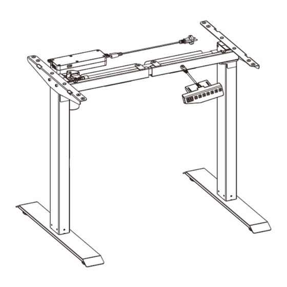
Page 7: Overview
OVERVIEW Feet Control panel Column Baffle Column (with motor) Hand switch Supporting beam Power cable Transmission rod Cable tie Supporting plate... - Page 8 Control Panel Display Memory Alert Position Raise Lower 1/2/3 Adjust the desk upwards Adjust the desk downwards Position 1, first height position saved by the user Position 2, second height position saved by the user Position 3, third height position saved by the user Height memory function Alert button to remind users to shift position...
-
Page 9: Assembly
ASSEMBLY Step 1: Install the feet • Attach the Feet (1) to the bottom of the Lifting Columns (2 & 3) using x8 M6 Hex Screws (A). A M6 Hex Screw (x8) C 5mm Allen Key... - Page 10 Step 2: Install supporting beam • Loosen screws on the supporting beam (4) using the 4mm Allen key (C), then extend the supporting beam. • Adjust the supporting beam size (4) according to your desktop size. C 4mm Allen Key Extend...
- Page 11 Step 3: Install supporting beam • Attach the supporting beam to the lifting columns (2)(3), using x2 M8 Hex Screw (B). • Tighten screws on supporting beam with wrench 4mm Allen key (C). B M8 Hex Screw (x2) C 4mm Allen Key C 5mm Allen Key...
- Page 12 Step 4: Install Transmission rod • Loosen the nut on the left side of the Transmission rod (5) and insert it into the lifting column (2). Tighten the nut on the Transmission rod using the wrench (G). • Rotate the right side of the Transmission rod (5) to insert it into the motor on the lifting column (3).
- Page 13 Step 5: Install Supporting plate • Use M8 Hex Screws (B) to attach the supporting plates (6) to the lifting columns (2)(3). • Secure the supporting plates in place using the M6 Hex Screws (A). A M6 Hex Screw (x4) B M8 Hex Screw (x2) C 5mm Allen key...
- Page 14 Step 6: Install Control box and Control panel • Attach the desktop to the assembled frame using the ST4.2 screws (F) and a drill. • Attach the control panel (9) to the front edge of the desktop using the ST4.2 screws (F) and a drill.
- Page 15 Step 7: Install Baffle Install the Baffles (8), using x4 M4 Hex Screws (E) and the 2.5mm Allen key (D). E M4 Hex Screw (x4) D 2.5mm Allen key...
- Page 16 Step 8: Connect the Cables • Connect the Cables to the Control Box (7). • Use the cable tie (11) to manage all the cables underneath the desktop. Remove backing Secure Manage cables Power port Power port Motor Motor Control Control panel panel...
-
Page 17: Operation
OPERATION Adjusting the Height "▲" "▼" Press the buttons to adjust the height of the desk. The display will show the current height. Memory Setting • Press "▲" or "▼" buttons to adjust the height to the desired height. Press "M" to save the height and the screen will display "... - Page 18 Collision Avoidance During height adjustment, if tabletop comes in contact with another object, it instantly stops and reverses to avoid damage. • Press and hold the “▲” “▼” buttons for 5 seconds at the same time to adjust the collision avoidance sensitivity. Select between the 4 levels; Setting Sensitivity Medium...
-
Page 19: Specifications
SPECIFICATIONS Column Number Maximum Load 70kg Speed 25mm/s Input Voltage 100-240V Lowest Position 710mm Highest Position 1210mm 1000-1600mm Desktop Size 500-800mm Continuous operation for 2 mins at most after pause Duty Cycle for 18 mins Applicable Temperature 0~40°C... -
Page 20: Troubleshooting
TROUBLESHOOTING The following tips will help you detect and eliminate common faults. If the fault you met is not listed below, contact help.Kogan.com for support. Problem Solution Check if all the cables are connected well No response from control panel after connecting the power. -
Page 21: Notes
NOTES... - Page 24 Need more information? We hope that this user guide has given you the assistance needed for a simple set-up. For the most up-to-date guide for your product, as well as any additional assistance you may require, head online to help.kogan.com...
Need help?
Do you have a question about the MEMORY ELSTD1MTMBA and is the answer not in the manual?
Questions and answers