Mitsubishi Electric SUZ-KA25VA Service Manual
Split-type, heat pump air conditioners
Hide thumbs
Also See for SUZ-KA25VA:
- Technical & service manual (102 pages) ,
- Manual (118 pages) ,
- Technical data book (110 pages)
Table of Contents
Advertisement
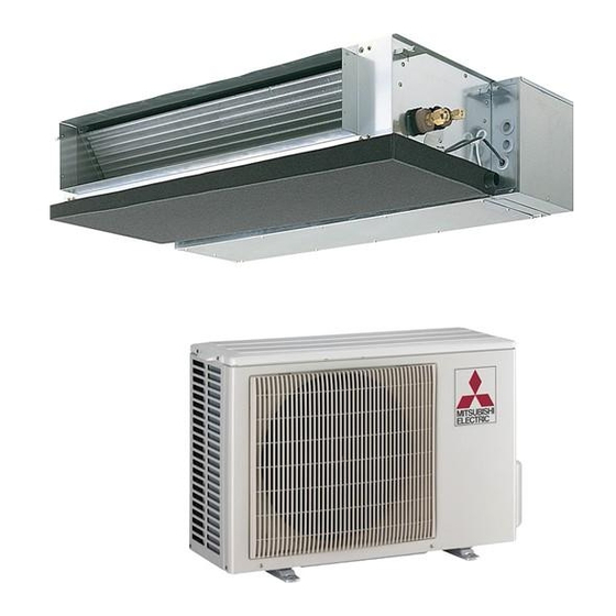
SPLIT-TYPE, HEAT PUMP AIR CONDITIONERS
TECHNICAL & SERVICE MANUAL
R410A
Outdoor unit
[model names] [Service Ref.]
SUZ-KA25VA.TH
SUZ-KA25VA
SUZ-KA35VA.TH
SUZ-KA35VA
SUZ-KA25VAH.TH SUZ-KA25VAHR1.TH
SUZ-KA25VAH
SUZ-KA35VAH.TH SUZ-KA35VAHR1.TH
SUZ-KA35VAH
SUZ-KA50VA.TH
SUZ-KA50VA
SUZ-KA50VA
SUZ-KA50VAR2.TH
SUZ-KA60VA.TH
SUZ-KA60VA
SUZ-KA60VA
SUZ-KA60VAR2.TH
SUZ-KA71VA.TH
SUZ-KA71VA
SUZ-KA71VA
SUZ-KA25VA(H).TH
SUZ-KA35VA(H).TH
NOTE:
This service manual describes technical data of the
outdoor units.
RoHS compliant products have <G> mark on the spec
name plate.
For servicing of RoHS compliant products, refer to the
RoHS Parts List.
.TH
1
.TH
1
.TH
1
Indication of
model name
SUZ-KA25VA(H)R1.TH
SUZ-KA35VA(H)R1.TH
SUZ-KA25VAR1.TH
SUZ-KA35VAR1.TH
CONTENTS
2. TECHNICAL CHANGES .................................... 3
3. PART NAMES AND FUNCTIONS ...................... 7
4. SPECIFICATION ................................................. 8
5. NOISE CRITERIA CURVES .............................. 12
6. OUTLINES AND DIMENSIONS ........................ 13
7. WIRING DIAGRAM ........................................... 15
8. REFRIGERANT SYSTEM DIAGRAM .............. 23
9. PERFORMANCE CURVES .............................. 29
10. ACTUATOR CONTROL .................................... 57
11. SERVICE FUNCTIONS ..................................... 58
12. TROUBLESHOOTING ...................................... 58
13. DISASSEMBLY INSTRUCTIONS ................... 103
14. PARTS LIST .................................................... 113
15. RoHS PARTS LIST ......................................... 119
April 2009
No.OC322
REVISED EDITION-E
HFC
utilized
R410A
Revision:
• SUZ-KA25/35VA(H)R1.TH
are added in REVISED
EDITION-E.
• Some descriptions
have been modified.
• Please void OC322
REVISED EDITION-D.
Advertisement
Table of Contents
Troubleshooting

Subscribe to Our Youtube Channel
Related Manuals for Mitsubishi Electric SUZ-KA25VA


Summary of Contents for Mitsubishi Electric SUZ-KA25VA
-
Page 1: Table Of Contents
April 2009 No.OC322 REVISED EDITION-E utilized R410A TECHNICAL & SERVICE MANUAL R410A Outdoor unit Revision: [model names] [Service Ref.] • SUZ-KA25/35VA(H)R1.TH SUZ-KA25VA.TH SUZ-KA25VAR1.TH are added in REVISED SUZ-KA25VA EDITION-E. SUZ-KA35VA.TH SUZ-KA35VAR1.TH SUZ-KA35VA • Some descriptions SUZ-KA25VAH.TH SUZ-KA25VAHR1.TH SUZ-KA25VAH have been modified. -
Page 2: Combination Of Indoor And Outdoor Units
COMBINATION OF INDOOR AND OUTDOOR UNITS 1-1. INDOOR UNIT SERVICE MANUAL Outdoor unit Heat pump type Indoor unit SUZ- Service KA35VA(H).TH KA25VA(H).TH KA50VA KA60VA Service Ref. KA71VA KA35VA(H)R1.TH KA50VAR2.TH KA60VAR2.TH KA25VA(H)R1.TH Manual No. — — — — SLZ-KA25VA(L).TH — — —... -
Page 3: Technical Changes
• Specification of LEV body has been changed. • Stop valve has been changed. 3. Precharged refrigerant amount has been changed. (900g → 800g : SUZ-KA25VA(H)R1.TH) 4. Fan motor has been changed. (RC0J50-AL → RC0J50-DB) 5. Outdoor heat exchanger temperature thermistor (RT68) has been added. - Page 4 SUZ-A18VR SUZ-KA50VA.TH SUZ-A24VR SUZ-KA60VA.TH 1. Indication of capacity has been changed.(BTU base → kW base) 2. Power supply method has been changed (change to supply from outdoor unit). 3. Outdoor electronic control P.C. board has been changed. 4. Noise filter P.C. board has been changed. 5.
- Page 5 New Specification Current Specification The incompatible refrigerant oil easily separates from Since refrigerant and refrigerant oil are compatible with refrigerant and is in the upper layer inside the suction muffler. each other, refrigerant oil backs to the compressor through Raising position of the oil back hole enables to back the the lower position oil back hole.
- Page 6 2. Refrigerant piping 1 Specifications Use the refrigerant pipes that meet the following specifications. Outside diameter Wall thickness Pipe Insulation material 6.35 For liquid Heat resisting foam plastic 9.52 Specific gravity 0.045 Thickness 9.52 8 mm For gas 12.7 15.88 •...
-
Page 7: Part Names And Functions
PART NAMES AND FUNCTIONS SUZ-KA25VAR1.TH SUZ-KA25VA.TH SUZ-KA35VA.TH SUZ-KA35VAR1.TH SUZ-KA25VAH.TH SUZ-KA25VAHR1.TH SUZ-KA35VAH.TH SUZ-KA35VAHR1.TH ACCESSORIES OUTDOOR UNIT Air inlet (back and side) Piping SUZ-KA25VA.TH SUZ-KA35VA.TH Drain hose SUZ-KA25VAR1.TH SUZ-KA35VAR1.TH Air outlet Drain socket Drain outlet SUZ-KA50VA.TH SUZ-KA50VA .TH SUZ-KA50VAR2.TH SUZ-KA60VA.TH SUZ-KA60VA .TH SUZ-KA60VAR2.TH SUZ-KA71VA.TH SUZ-KA71VA... -
Page 8: Specification
SPECIFICATION SUZ-KA50VA.TH SUZ-KA25VA(H).TH SUZ-KA25VA(H)R1.TH SUZ-KA35VA(H)R1.TH SUZ-KA35VA(H).TH Outdoor Service Ref. SUZ-KA50VA Cooling Cooling Cooling Cooling Function Cooling Heating Heating Heating Heating Heating Single phase Single phase Single phase Single phase Single phase Power supply 230V, 50Hz 230V, 50Hz 230V, 50Hz 230V, 50Hz 230V, 50Hz 3.65... - Page 9 SUZ-KA60VA.TH SUZ-KA71VA.TH SUZ-KA50VAR2.TH SUZ-KA60VAR2.TH SUZ-KA71VA Outdoor Service Ref. SUZ-KA60VA Function Cooling Heating Heating Cooling Heating Cooling Heating Cooling Single phase Single phase Single phase Single phase Power supply 230V, 50Hz 230V, 50Hz 230V, 50Hz 230V, 50Hz 9.75 9.75 Starting current *1 6.75 10.30 9.45...
- Page 10 Specifications and rating conditions of main electric parts SUZ-KA25VA.TH SUZ-KA25VAH.TH SUZ-KA35VA.TH SUZ-KA35VAH.TH Model SUZ-KA25VA.TH SUZ-KA25VAH.TH SUZ-KA35VA.TH SUZ-KA35VAH.TH Item Current transformer (CT) ETA19Z59BZ Current transformer (CT761, CT781) ETQ19Z71AY Smoothing capacitor (C63A, C63B, C63C) 420V Diode module (DB61, DB65) D25×B60 Fuse (F61)
- Page 11 SUZ-KA25VAR1.TH SUZ-KA25VAHR1.TH SUZ-KA35VAR1.TH SUZ-KA35VAHR1.TH SUZ-KA50VAR2.TH Model SUZ-KA25VAR1.TH SUZ-KA25VAHR1.TH SUZ-KA35VAR1.TH SUZ-KA35VAHR1.TH SUZ-KA50VAR2.TH Item (CT) 20 A Current transformer (CT761, CT781) 15 A — (C61) 620 μF 420 V Smoothing capacitor (C62, C63) 620 μF 420 V (DB61) 15 A 600 V 25 A 600 V Diode module (DB65)
-
Page 12: Noise Criteria Curves
NOISE CRITERIA CURVES SUZ-KA25VA.TH SUZ-KA25VAR1.TH SUZ-KA35VA.TH SUZ-KA35VAR1.TH SUZ-KA25VAH.TH SUZ-KA25VAHR1.TH SUZ-KA35VAH.TH SUZ-KA35VAHR1.TH FAN SPEED FUNCTION SPL(dB(A)) LINE FAN SPEED FUNCTION SPL(dB(A)) LINE COOLING COOLING High High Med. Med. HEATING HEATING Test conditions, Test conditions, Cooling : Dry-bulb temperature 35 Wet-bulb temperature (24 ) -
Page 13: Outlines And Dimensions
OUTLINES AND DIMENSIONS SUZ-KA25VA.TH SUZ-KA25VAH.TH SUZ-KA25VAR1.TH SUZ-KA25VAHR1.TH SUZ-KA35VA.TH SUZ-KA35VAH.TH SUZ-KA35VAR1.TH SUZ-KA35VAHR1.TH OUTDOOR UNIT Unit: mm REQUIRED SPACE Basically open 100mm or more without any obstruction in front and on both sides of the unit. Drain hole 42 (SUZ-KA25/KA35VA) Drain hole 33 (SUZ-KA25/KA35VAH) - Page 14 SUZ-KA50VA.TH SUZ-KA50VA .TH SUZ-KA50VAR2.TH Unit: mm SUZ-KA60VA.TH SUZ-KA60VA .TH SUZ-KA60VAR2.TH SUZ-KA71VA.TH SUZ-KA71VA REQUIRED SPACE OUTDOOR UNIT Open as a rule Drain holes 500mm or more if the front and both sides are open 100mm or more 200mm or more if 100mm or more there are obstacles to both sides...
-
Page 15: Wiring Diagram
WIRING DIAGRAM SUZ-KA25VA.TH MODELS WIRING DIAGRAM SUZ-KA35VA.TH OUTDOOR UNIT... - Page 16 SUZ-KA25VAR1.TH SUZ-KA35VAR1.TH OUTDOOR UNIT...
- Page 17 SUZ-KA25VAH.TH MODELS WIRING DIAGRAM SUZ-KA35VAH.TH OUTDOOR UNIT...
- Page 18 SUZ-KA25VAHR1.TH SUZ-KA35VAHR1.TH OUTDOOR UNIT...
- Page 19 SUZ-KA50VA.TH SUZ-KA50VA SUZ-KA60VA.TH SUZ-KA60VA MODELS WIRING DIAGRAM OUTDOOR UNIT...
- Page 20 SUZ-KA50VAR2.TH OUTDOOR UNIT...
- Page 21 SUZ-KA60VAR2.TH OUTDOOR UNIT...
- Page 22 SUZ-KA71VA.TH SUZ-KA71VA MODEL WIRING DIAGRAM OUTDOOR UNIT...
-
Page 23: Refrigerant System Diagram
REFRIGERANT SYSTEM DIAGRAM SUZ-KA25VA.TH Unit: mm SUZ-KA25VAH.TH OUTDOOR UNIT Refrigerant pipe 9.52 4-way valve (with heat insulator) Muffler Stop valve (with service port) Outdoor Muffler Discharge heat Flared connection exchanger temperature thermistor RT62 Ambient Compressor temperature thermistor Defrost RT65 thermistor... - Page 24 SUZ-KA35VA.TH Unit: mm SUZ-KA35VAH.TH OUTDOOR UNIT Refrigerant pipe 9.52 4-way valve (with heat insulator) Muffler Stop valve (with service port) Outdoor Muffler Discharge heat Flared connection exchanger temperature thermistor RT62 Ambient Compressor temperature thermistor RT65 Defrost thermistor RT61 Capillary tube 3.0×...
- Page 25 SUZ-KA50VA.TH SUZ-KA50VA Unit: mm SUZ-KA60VA.TH SUZ-KA60VA OUTDOOR UNIT Refrigerant pipe 12.7 (SUZ-KA50VA) Muffler #100 (with heat insulator) 15.88 (SUZ-KA60VA) 4-way valve Stop valve (with service port) Outdoor Flared connection Discharge heat Ambient temperature exchanger temperature thermistor Defrost thermistor RT62 thermistor RT65 RT61 Compressor...
- Page 26 SUZ-KA60VAR2.TH Unit:mm OUTDOOR UNIT Refrigerant pipe 15.88 Muffler #100 (with heat insulator) 4-way valve Stop valve High-pressure (with service port) Outdoor switch Flared connection Discharge heat Ambient temperature exchanger temperature thermistor Defrost thermistor RT62 thermistor RT65 RT61 Compressor Outdoor heat exchanger temperature thermistor...
- Page 27 SUZ-KA25VA.TH SUZ-KA25VAH.TH SUZ-KA25VAR1.TH SUZ-KA25VAHR1.TH SUZ-KA35VA.TH SUZ-KA35VAH.TH SUZ-KA35VAR1.TH SUZ-KA35VAHR1.TH MAX. REFRIGERANT PIPING LENGTH Refrigerant piping Piping size O.D: mm Models Max. length: m Liquid SUZ-KA25VA.TH SUZ-KA35VA.TH SUZ-KA25VAH.TH SUZ-KA35VAH.TH 9.52 6.35 SUZ-KA25VAR1.TH SUZ-KA35VAR1.TH SUZ-KA25VAHR1.TH SUZ-KA35VAHR1.TH MAX. HEIGHT DIFFERENCE Indoor (SLZ/SEZ) unit Max. Height...
- Page 28 SUZ-KA50VA.TH SUZ-KA50VA .TH SUZ-KA50VAR2.TH SUZ-KA60VA.TH SUZ-KA60VA .TH SUZ-KA60VAR2.TH SUZ-KA71VA.TH SUZ-KA71VA MAX. REFRIGERANT PIPING LENGTH Refrigerant piping Piping size O.D: mm Model Max. length: m Liquid SUZ-KA50VA.TH 12.7 SUZ-KA50VA SUZ-KA50VAR2.TH 6.35 SUZ-KA60VA.TH SUZ-KA60VA 15.88 SUZ-KA60VAR2.TH SUZ-KA71VA.TH 9.52 SUZ-KA71VA MAX. HEIGHT DIFFERENCE Indoor (SLZ/SEZ) unit...
-
Page 29: Performance Curves
PERFORMANCE CURVES Model SLZ-KA25VA(L)/SUZ-KA25VA SLZ-KA35VA(L)/SUZ-KA35VA SLZ-KA50VA(L)/SUZ-KA50VA The standard data contained in these specifications applies only to the operation of the air conditioner under normal condition. Operating conditions vary according to the areas where these units are installed. The following information has been provided to clarify the operating characteristics of the air conditioner under the conditions indicated by the performance curve. - Page 30 Indoor intake air Wet-bulb temperature( ) Indoor intake air Wet-bulb temperature( ) 45 46 45 46 Outdoor intake air Dry-bulb temperature ( ) Outdoor intake air Dry-bulb temperature ( ) Indoor intake air Wet-bulb Indoor intake air Wet-bulb temperature( ) temperature( ) 45 46 45 46...
- Page 31 11.0 13.0 Outdoor intake air Wet-bulb temperature ( ) Outdoor intake air Wet-bulb temperature ( ) NOTE: The above curves are for the heating operation without any frost. SUZ-KA25VA(H) SUZ-KA25VA(H) SUZ-KA25VA(H) SUZ-KA25VA(H) Correction of Heating total input Correction of Cooling total input...
-
Page 32: Heat Operation
1 Both indoor and outdoor unit are under the Dry-bulb temperature Relative humidity(%) same temperature/humidity condition. 2 Air flow : High speed 3 Operation: TEST RUN OPERATION SUZ-KA35VA(H) SUZ-KA50VA SUZ-KA25VA(H) (kgf/ [Gauge]) (MPa [Gauge]) (kgf/ [Gauge]) (MPa [Gauge]) (kgf/ [Gauge]) (MPa [Gauge]) 35(°C) -
Page 33: Indoor Unit
Model SEZ-KC25VA/SUZ-KA25VA SEZ-KA35VA/SUZ-KA35VA SEZ-KA50VA/SUZ-KA50VA SEZ-KA60VA/SUZ-KA60VA SEZ-KA71VA/SUZ-KA71VA The standard data contained in these specifications applies only to the operation of the air conditioner under normal condition. Operating conditions vary according to the areas where these units are installed. The following information has been provided to clarify the operating characteristics of the air conditioner under the conditions indicated by the performance curve. - Page 34 Indoor intake air Wet-bulb temperature( ) Indoor intake air Wet-bulb temperature( ) 45 46 45 46 Outdoor intake air Dry-bulb temperature ( ) Outdoor intake air Dry-bulb temperature ( ) Indoor intake air Wet-bulb temperature( ) Indoor intake air Wet-bulb temperature( ) 45 46 45 46 Outdoor intake air Dry-bulb temperature ( )
- Page 35 Heating capacity Total input (heating) 25.2 22.7 24.5 25.3 23.2 20.9 22.6 23.3 21.3 19.2 20.7 21.4 19.4 17.4 18.9 19.4 17.4 15.7 17.0 17.5 15.5 14.0 15.1 15.5 13.6 12.2 13.2 13.6 11.6 10.5 11.3 11.7 Outdoor intake air Wet-bulb temperature ( ) Outdoor intake air Wet-bulb temperature ( ) Total input (heating) Heating capacity...
- Page 36 SUZ-KA25VA(H) SUZ-KA25VA(H) SUZ-KA25VA(H) SUZ-KA25VA(H) Correction of Cooling capacity Correction of Cooling total input Correction of Heating total input Correction of Heating capacity 150(Hz) 150(Hz) 150(Hz) 150(Hz) The operational frequency of compressor The operational frequency of compressor The operational frequency of compressor...
- Page 37 OUTDOOR LOW PRESSURE AND OUTDOOR UNIT CURRENT COOL operation 1 Both indoor and outdoor unit are under the Relative humidity(%) Dry-bulb temperature same temperature/humidity condition. 2 Air flow : High speed 3 Operation: TEST RUN OPERATION SUZ-KA25VA(H) SUZ-KA35VA(H) SUZ-KA50VA SUZ-KA60VA (kgf/ [Gauge]) (MPa [Gauge]) (kgf/...
- Page 38 HEAT operation Condition indoor: Dry bulb temperature 20.0°C Wet bulb temperature 14.5°C Condition outdoor: Dry bulb temperature 2,7,15,20.0°C Wet bulb temperature 1,6,12,14.5°C SUZ-KA25VA(H) SUZ-KA35VA(H) SUZ-KA50VA SUZ-KA60VA 25( ) 25( ) 25( ) 25( ) Ambient temperature(°C) Ambient temperature(°C) Ambient temperature(°C) Ambient temperature(°C)
- Page 39 PERFORMANCE DATA COOLING operation at Rated frequency SLZ-KA25VA(L)/SUZ-KA25VA(H) CAPACITY : 2.5(kW) INPUT : 690(W) SHF : 0.86 OUTDOOR D.B.( ) INDOOR INDOOR D.B.( ) W.B.( ) SHC SHF INPUT SHC SHF INPUT SHC SHF INPUT SHC SHF INPUT 2.94 2.00 0.68 2.81 1.91 0.68...
- Page 40 PERFORMANCE DATA COOLING operation at Rated frequency SLZ-KA25VA(L)/SUZ-KA25VA(H) CAPACITY : 2.5(kW) INPUT : 690(W) SHF : 0.86 OUTDOOR D.B.( ) INDOOR INDOOR D.B.( ) W.B.( ) SHC SHF INPUT SHC SHF INPUT SHC SHF INPUT 2.45 1.67 0.68 2.25 1.53 0.68 2.08 1.41 0.68...
- Page 41 PERFORMANCE DATA COOLING operation at Rated frequency SLZ-KA35VA(L)/SUZ-KA35VA(H) CAPACITY : 3.5(kW) INPUT : 1060(W) SHF : 0.77 OUTDOOR D.B.( ) INDOOR INDOOR D.B.( ) W.B.( ) SHC SHF INPUT SHC SHF INPUT SHC SHF INPUT SHC SHF INPUT 4.11 2.43 0.59 3.94 2.32 0.59 3.78 2.23 0.59 3.64 2.15 0.59...
- Page 42 PERFORMANCE DATA COOLING operation at Rated frequency SLZ-KA35VA(L)/SUZ-KA35VA(H) CAPACITY : 3.5(kW) INPUT : 1060(W) SHF : 0.77 OUTDOOR D.B.( ) INDOOR INDOOR D.B.( ) W.B.( ) SHC SHF INPUT SHC SHF INPUT SHC SHF INPUT 3.43 2.02 0.59 1039 3.15 1.86 0.59 1102 2.91 1.71 0.59 1145...
- Page 43 PERFORMANCE DATA COOLING operation at Rated frequency SLZ-KA50VA(L)/SUZ-KA50VA CAPACITY : 4.6(kW) INPUT : 1630(W) SHF : 0.68 OUTDOOR D.B.( ) INDOOR INDOOR D.B.( ) W.B.( ) SHC SHF INPUT SHC SHF INPUT SHC SHF INPUT SHC SHF INPUT 4.78 2.39 0.50 1500 4.97...
- Page 44 PERFORMANCE DATA COOLING operation at Rated frequency SLZ-KA50VA(L)/SUZ-KA50VA CAPACITY : 4.6(kW) INPUT : 1630(W) SHF : 0.68 OUTDOOR D.B.( ) INDOOR INDOOR D.B.( ) W.B.( ) SHC SHF INPUT SHC SHF INPUT SHC SHF INPUT 1.91 1760 2.07 1695 3.82 0.50 2.25 1597...
- Page 45 PERFORMANCE DATA COOLING operation at Rated frequency SEZ-KC25VA/SUZ-KA25VA(H) CAPACITY : 2.5(kW) INPUT : 730(W) SHF : 0.74 OUTDOOR D.B.( ) INDOOR INDOOR D.B.( ) W.B.( ) SHC SHF INPUT SHC SHF INPUT SHC SHF INPUT SHC SHF INPUT 2.94 1.65 0.56 2.81 1.58 0.56...
- Page 46 PERFORMANCE DATA COOLING operation at Rated frequency SEZ-KC25VA/SUZ-KA25VA(H) CAPACITY : 2.5(kW) INPUT : 730(W) SHF : 0.74 OUTDOOR D.B.( ) INDOOR INDOOR D.B.( ) W.B.( ) SHC SHF INPUT SHC SHF INPUT SHC SHF INPUT 2.45 1.37 0.56 2.25 1.26 0.56 2.08 1.16 0.56...
- Page 47 PERFORMANCE DATA COOLING operation at Rated frequency SEZ-KA35VA/SUZ-KA35VA(H) CAPACITY : 3.5(kW) INPUT : 1060(W) SHF : 0.77 OUTDOOR D.B.( ) INDOOR INDOOR D.B.( ) W.B.( ) SHC SHF INPUT SHC SHF INPUT SHC SHF INPUT SHC SHF INPUT 4.11 2.43 0.59 3.94 2.32 0.59 3.78 2.23 0.59 3.64 2.15 0.59...
- Page 48 PERFORMANCE DATA COOLING operation at Rated frequency SEZ-KA35VA/SUZ-KA35VA(H) CAPACITY : 3.5(kW) INPUT : 1060(W) SHF : 0.77 OUTDOOR D.B.( ) INDOOR INDOOR D.B.( ) W.B.( ) SHC SHF INPUT SHC SHF INPUT SHC SHF INPUT 3.43 2.02 0.59 1039 3.15 1.86 0.59 1102 2.91 1.71 0.59 1145...
- Page 49 PERFORMANCE DATA COOLING operation at Rated frequency SEZ-KA50VA/SUZ-KA50VA CAPACITY : 5.0(kW) INPUT : 1780(W) SHF : 0.75 OUTDOOR D.B.( ) INDOOR INDOOR D.B.( ) W.B.( ) SHC SHF INPUT SHC SHF INPUT SHC SHF INPUT SHC SHF INPUT 2.96 0.57 1638 3.08 0.57...
- Page 50 PERFORMANCE DATA COOLING operation at Rated frequency SEZ-KA50VA/SUZ-KA50VA CAPACITY : 5.0(kW) INPUT : 1780(W) SHF : 0.75 OUTDOOR D.B.( ) INDOOR INDOOR D.B.( ) W.B.( ) SHC SHF INPUT SHC SHF INPUT SHC SHF INPUT 4.15 2.37 0.57 1922 4.50 2.57 0.57 1851...
- Page 51 PERFORMANCE DATA COOLING operation at Rated frequency SEZ-KA60VA/SUZ-KA60VA CAPACITY : 5.5(kW) INPUT : 1960(W) SHF : 0.75 OUTDOOR D.B.( ) INDOOR INDOOR SHC SHF INPUT SHC SHF INPUT SHC SHF INPUT SHC SHF INPUT D.B.( ) W.B.( ) 3.26 1803 3.39 1725 5.72...
- Page 52 PERFORMANCE DATA COOLING operation at Rated frequency SEZ-KA60VA/SUZ-KA60VA CAPACITY : 5.5(kW) INPUT : 1960(W) SHF : 0.75 OUTDOOR D.B.( ) INDOOR INDOOR D.B.( ) W.B.( ) SHC SHF INPUT SHC SHF INPUT SHC SHF INPUT 2.60 0.57 2117 2.82 0.57 2038 4.57 3.07...
- Page 53 PERFORMANCE DATA COOLING operation at Rated frequency SEZ-KA71VA/SUZ-KA71VA CAPACITY : 7.1(kW) INPUT : 2460(W) SHF : 0.74 OUTDOOR D.B.( ) INDOOR INDOOR SHF INPUT SHF INPUT SHF INPUT SHF INPUT D.B.( ) W.B.( ) 8.34 4.67 0.56 1968 7.99 4.47 0.56 2066 7.67...
- Page 54 PERFORMANCE DATA COOLING operation at Rated frequency SEZ-KA71VA/SUZ-KA71VA CAPACITY : 7.1(kW) INPUT : 2460(W) SHF : 0.74 OUTDOOR D.B.( ) INDOOR INDOOR D.B.( ) W.B.( ) SHF INPUT SHC SHF INPUT SHC SHF INPUT 6.96 3.90 0.56 2411 6.39 3.58 0.56 2558 5.89...
- Page 55 PERFORMANCE DATA HEATING operation SLZ-KA25VA(L)/SUZ-KA25VA(H) at Rated frequency CAPACITY : 3.0(kW) INPUT : 830(W) OUTDOOR W.B.( ) INDOOR D.B.( ) INPUT INPUT INPUT INPUT INPUT INPUT INPUT INPUT 3.81 4.20 1.50 1.89 2.28 2.67 3.06 3.45 1.41 1.80 2.16 2.55 2.91...
- Page 56 SEZ-KC25VA/SUZ-KA25VA(H) at Rated frequency CAPACITY : 3.0(kW) INPUT : 830(W) OUTDOOR W.B.( ) INDOOR INPUT INPUT INPUT INPUT INPUT INPUT INPUT INPUT D.B.( ) 1.50 1.89 2.28 2.67 3.06 3.45 3.81 4.20 1.41 1.80 2.16 2.55 2.91 3.30 3.66 4.04 1.23...
-
Page 57: Actuator Control
Dry ....OFF <COOL> <HEAT> 5 seconds 5 seconds Compressor R.V.coil ON or OFF ON or OFF Outdoor fan motor 10-3. Relation between main sensor and actuator SUZ-KA25VA(H).TH SUZ-KA35VA(H).TH Actuator Purpose Sensor Outdoor Indoor Defrost Compressor RV-coil fan motor fan motor heater... -
Page 58: Service Functions
Protection Outdoor heat exchanger temperature Cooling: High pressure protection SERVICE FUNCTIONS SUZ-KA25VA(H) SUZ-KA35VA(H) CHANGE IN DEFROST SETTING <JS> When the JS wire of the outdoor Inverter P.C. board is cut/ soldered, the defrost finish temperature is changed. (Refer to 12-6-1 SUZ-KA25/35VA(H).TH) (Refer to 12-6-3 SUZ-KA25/35VA(H)R1.TH) -
Page 59: Failure Mode Recall Function
12-2. Failure mode recall function As this air conditioner has a function to memorize all the failures that had happened, the latest failure detail can be recalled by following the procedures below. Use this function when the check code is not displayed with wired remote controller or the remote controller at use is wireless type. -
Page 60: Wired Remote Controller
12-2-2. Wired remote controller CHECK button Turn on the power. Refrigerant address Press the [CHECK] button twice. TEMP. button Set refrigerant address with [TEMP] button IC: Indoor unit if system control is used. OC: Outdoor unit Press the [ON/OFF] button to stop the self-check. °C °C SIMPLE... - Page 61 12-2-4. Outdoor unit failure mode table SUZ-KA25VA(H) SUZ-KA35VA(H) (Except for SUZ-KA25/35VA(H)R1.TH) Abnormal point LED indication Details of abnormal Detection method Check point (Failure mode) (Outdoor unit) 1-time flash every Outdoor thermistors Discharge temperature When thermistors short or open during •Check the outdoor thermistors 2.5 seconds...
- Page 62 SUZ-KA50VA SUZ-KA60VA SUZ-KA71VA (Except for SUZ-KA50VAR2.TH) Outdoor LED indication Abnormal point Details of abnormal Detecting method Check point (Failure mode) LED1 LED2 Discharge temperature When a short circuit is detected in the • Check the outdoor thermistors. Outdoor thermistors Lighting Once thermistor thermistor during operation, or when an...
- Page 63 Outdoor LED indication Abnormal point Details of abnormal Detecting method Check point (Failure mode) LED1 LED2 When overcurrent is detected after Once Goes out • Check the connection of the Overcurrent protection IPM protection 30 seconds of compressor start-up. compressor connecting wire. When overcurrent is detected within •...
- Page 64 SUZ-KA25VA(H)R1.TH SUZ-KA35VA(H)R1.TH SUZ-KA50VAR2.TH Abnormal point LED indication Condition Correspondence (Failure mode/protection) (Outdoor P.C. board) — — — Outdoor power system Overcurrent protection stop is • Reconnect connectors. continuously performed 3 times within • Refer to 12-5. "How 1 minute after the compressor gets to check inverter/ —...
- Page 65 12-3. Troubleshooting check table Inverter P.C. board (Parts side) SUZ-KA25VA(H) SUZ-KA35VA(H) (Except for SUZ-KA25/35VA(H)R1.TH) NOTE 1. The location of LED is illustrated at the right figure. Refer to 12-6-1. Flashing 2. LED lights up during normal operation. Symptom LED indication...
- Page 66 SUZ-KA50VA SUZ-KA60VA SUZ-KA71VA (Except for SUZ-KA50VAR2.TH) Indication Symptom Abnormal point/Condition Condition Correspondence LED1 (Red) LED2 (Yellow) Outdoor unit • Check the connection of the compressor connecting When IPM protection stop or lock protection stop is continuously does not wire. performed three times within 1 minute after the compressor gets operate.
- Page 67 Indication No. Symptom Abnormal point/Condition Condition Correspondence LED1 (Red) LED2 (Yellow) These symptoms do not mean any abnormality of the Primary current protection When the input current exceeds 15A. Outdoor unit Once Lighting operates. product, but check the following points. Secondary current protection When the current of the compressor exceeds 15A.
- Page 68 SUZ-KA25VA(H)R1.TH SUZ-KA35VA(H)R1.TH SUZ-KA50VAR2.TH Abnormal point/ Con- Symptom LED indication dition Outdoor unit 1-time flash every Outdoor power sys- Overcurrent protection stop is continuously performed 3 times • Reconnect connector of compres- does not oper- 2.5 seconds within 1 minute after the compressor gets started, or failure of sor.
- Page 69 12-4. Trouble criterion of main parts (1) SUZ-KA25VA.TH SUZ-KA35VA.TH SUZ-KA25VAR1.TH SUZ-KA35VAR1.TH SUZ-KA25VAH.TH SUZ-KA35VAH.TH SUZ-KA25VAHR1.TH SUZ-KA35VAHR1.TH Part name Check method and criterion Figure Defrost thermistor (RT61) Fin temperature Measure the resistance with a tester. thermistor (RT64) Ambient temperature Refer to 12-6. “Test point diagram and voltage”, 12-6-1. or 12-6-3.
- Page 70 12-4. Trouble criterion of main parts (2) SUZ-KA50VA.TH SUZ-KA50VA .TH SUZ-KA50VAR2.TH SUZ-KA60VA.TH SUZ-KA60VA .TH SUZ-KA60VAR2.TH SUZ-KA71VA.TH SUZ-KA71VA Part name Check method and criterion Figure Defrost thermistor Measure the resistance with a tester. (RT61) Fin temperature Refer to 12-6. “Test point diagram and voltage”, 12-6-4. “Outdoor thermistor (RT64) electronic control P.C.
-
Page 71: Troubleshooting Flow
[SUZ-KA25/35VA(H).TH] 12-5. Troubleshooting flow Outdoor unit does not operate. How to check inverter/compressor Disconnect the connector (CN61) between compressor and the intelligent power module (IPM). Check the voltage See B “Check of open phase”. between terminals. Are the voltages Check the resistance of the intelligent See C 'Check of intelligent power module'. - Page 72 [SUZ-KA25/35VA(H).TH] Check of compressor "Check of compressor Replace the compressor. winding". Is the compressor normal? "Check of compressor Is the compressor operation time". Does the Replace the compressor. operation time more than compressor operate 10 seconds? continuously? Check the refrigerant circuit. Check of compressor winding RED BLK ●...
- Page 73 [SUZ-KA25/35VA(H).TH] The thermistors in the outdoor unit are abnormal. Check of outdoor thermistors Disconnect the connectors CN641, CN642 and CN643 from the inverter P.C. board. Defrost thermistor RT61 (Check the characteristics of each thermistor.) Measure the resistance between CN641 Discharge temperature Reconnect the thermistor RT62...
- Page 74 [SUZ-KA25/35VA(H).TH] Outdoor fan motor does not operate. Check of outdoor fan motor Rotate the outdoor fan slowly by hand, and measure the Is the resistance Disconnect CN932 voltage of CN931 (Measurement between each terminal of Turn ON the from the inverter of feedback output).
-
Page 75: Check Of Lev (Expansion Valve)
[SUZ-KA25/35VA(H).TH] Outdoor unit does not operate at all or stops immediately due to over current. Check of current limiting resistor When the current-limiting resistor is open, the rush current limiting relay (X64) may not work properly. Turn ON the power Does the current-limiting resistor supply and press Replace the power P.C. - Page 76 [SUZ-KA25/35VA(H).TH] Check of LEV (Expansion valve) (For wired remote controller use model) Start Turn on power supply to the outdoor unit after checking LEV coil is mounted to the LEV body securely. Is "click - click" sound heard? Normal Or, do you feel vibration of the LEV coil with a hand? Disconnect the connector Replace the inverter P.C.
- Page 77 [SUZ-KA25/35VA(H).TH] Outdoor fan motor does not operate, or stops immediately after starting up. Check of inverter P.C. board Check the outdoor fan motor. Refer to12-5. . Is the fuse (F901) blown on the inverter P.C. board? Inverter P.C.board Check the connection of the connectors (Solder side) (CN931, CN932) of outdoor fan motor.
- Page 78 [SUZ-KA25/35VA(H).TH] How to check miswiring and serial signal error (when outdoor unit does not work) (For wireless remote controller use model) Turn OFF the power supply. Is there rated voltage in Check the power the power supply? supply. Turn ON the power supply. Is there rated voltage between outdoor terminal block S1 and Check the wiring.
- Page 79 [SUZ-KA25/35VA(H).TH] How to check miswiring and serial signal error (when outdoor unit does not work) (For wired remote controller use model) Turn OFF the power supply. Is there rated voltage in the Check the power power supply? supply. Turn ON the power supply. Is there rated voltage between outdoor terminal block S1 and Check the wiring.
- Page 80 [SUZ-KA25/35VA(H).TH SUZ-KA50/60/71VA SUZ-KA60VAR2.TH] Electromagnetic noise enters into TV sets or radios Is the unit earthed? Earth the unit. Is the distance between the Extend the distance between antennas and the indoor the antennas and the indoor unit within 3m, or is the unit, and/or the antennas and distance between the the outdoor unit.
- Page 81 [SUZ-KA50/60/71VA .TH SUZ-KA60VA .TH] Outdoor unit does not operate. (LED display: display OFF) Check of power supply Start Check the connecting of parts of main power supply circuit. Turn on power supply. Is there voltage of 230V AC in the Check the power supply cable.
- Page 82 [SUZ-KA50/60/71VA .TH SUZ-KA60VAR2.TH] When unit cannot operate neither by the remote controller nor by EMERGENCY OPERATION switch. Indoor unit does not operate. Outdoor unit does not operate. How to check miswiring and serial signal error (when outdoor unit does not work) (For wireless remote controller use model) As for indoor unit.
- Page 83 [SUZ-KA50/60/71VA .TH SUZ-KA60VAR2.TH] When unit cannot operate neither by the remote controller. Indoor unit does not operate. Outdoor unit does not operate. How to check miswiring and serial signal error (when outdoor unit does not work) (For wired remote controller use model) As for indoor unit.
- Page 84 [SUZ-KA50/60/71VA .TH SUZ-KA60VAR2.TH] The cooling operation or heating operation does not operate. (LED display: Both LED1 and LED2 lighting) Check of R.V. coil • When heating operation does not work. 1. Disconnect the lead wire leading to the compressor. 2. 3 minutes after turning on the power supply, start EMERGENCY OPERATION in HEAT mode.
- Page 85 [SUZ-KA50/60/71VA .TH SUZ-KA60VAR2.TH] When cooling, heat exchanger of non-operating indoor unit frosts. When heating, non-operating indoor unit get warm. LED display: LED1 LED2 Check of LEV Lighting Lighting 6 time Goes out Turn on power supply to the outdoor unit after checking LEV coil is mounted to the LEV body securely.
- Page 86 [SUZ-KA50/60/71VA .TH SUZ-KA60VAR2.TH] When thermistor is abnormal. Check of outdoor thermistors Disconnect the connector in the outdoor electronic control P.C. board or the outdoor power board Replace the thermistor. (see below table), and measure the resistance of thermistor. Is the thermistor normal? Reconnect the connector CN661 on the outdoor electronic control P.C.
- Page 87 [SUZ-KA50/60/71VA .TH SUZ-KA60VAR2.TH] When the operation frequency does not go up from lowest frequency. X Check of HPS SUZ-KA60VAR2.TH SUZ-KA71VA 1. Disconnect the connector CN681 in the electronic control P.C. board. 2. Check the resistance of HPS after 1 minutes have passed since the outdoor unit power supply was turned off. Infinity Check the resistance between Replace HPS.
- Page 88 [SUZ-KA25/35VA(H)R1.TH SUZ-KA50VAR2.TH] a How to check inverter/compressor Disconnect the connector (CN61) between compressor and the intelligent power module (IPM). Check the voltage between terminals. “Check of open phase”. Are the voltages balanced? Replace the inverter P.C. board. Check the compressor. “Check of compressor”.
- Page 89 [SUZ-KA25/35VA(H)R1.TH SUZ-KA50VAR2.TH] e Check of compressor winding Disconnect the connector (CN61) between the compressor and intelligent power module, and measure the resistance between the compressor terminals. <<Measurement point>> at 3 points BLK-WHT Measure the resistance between the lead wires at 3 points. BLK-RED WHT-RED <<Judgement>>...
- Page 90 [SUZ-KA25/35VA(H)R1.TH SUZ-KA50VAR2.TH] h Check of R.V. coil First of all, measure the resistance of R.V. coil to check if the coil is defective. Refer to 12-4. In case CN721 is not connected or R.V. coil is open, voltage is generated between the terminal pins of the connector although any signal is not being transmitted to R.V.
- Page 91 [SUZ-KA25/35VA(H)R1.TH SUZ-KA50VAR2.TH] j Check of power supply 280 - 370 VDC DB61 Disconnect the connector (CN61) between compressor and intelligent power module. Rectify indoor/outdoor Turn ON power supply and press connecting wire. EMERGENCY OPERATION switch. Inverter P.C. board (Solder side) Is there voltage 230 VAC Replace the indoor Does the left lamp of OPERATION...
- Page 92 [SUZ-KA25/35VA(H)R1.TH SUZ-KA50VAR2.TH] m Check of LEV (Expasion valve) (For wired remote controller use model) Start Turn on power supply to the outdoor unit after checking Normal LEV coil is fi xed to the LEV body securely. Is "click - click" sound heard? Or, do you feel vibration of the LEV coil with a hand? Disconnect the connector CN724 is there nor- Replace the inverter P.C.
- Page 93 [SUZ-KA25/35VA(H)R1.TH SUZ-KA50VAR2.TH] p How to check miswiring and serial signal error (For wireless remote controller use model) Turn OFF the power supply. Is there rated voltage in the Check the power supply. power supply? Turn ON the power supply. Is there rated voltage between outdoor termi- Check the wiring.
- Page 94 [SUZ-KA25/35VA(H)R1.TH SUZ-KA50VAR2.TH] q How to check miswiring and serial signal error (For wired remote controller use model) Turn OFF the power supply. Is there rated voltage in the Check the power supply. power supply? Turn ON the power supply. Is there rated voltage between outdoor termi- Check the wiring.
- Page 95 [SUZ-KA25/35VA(H)R1.TH SUZ-KA50VAR2.TH] r Electromagnetic noise enters into TV sets or radios Is the unit earthed? Earth the unit. Is the distance between the antennas Extend the distance between the antennas and and the indoor unit within 3 m, or is the the indoor unit, and/or the antennas and the distance between the antennas and the outdoor unit.
- Page 96 12-6. Test point diagram and voltage 12-6-1. Inverter P.C. board SUZ-KA25VA.TH SUZ-KA35VA.TH SUZ-KA25VAH.TH SUZ-KA35VAH.TH Back side of unit 230V AC Smoothing capacitor Smoothing capacitor Smoothing capacitor DB61 DB61 (C63C) (C63B) (C63A) 280V ~ 370V Fuse (F801) Fuse (F901) LED monitor...
- Page 97 12-6-2. Power P.C. board SUZ-KA25VA.TH SUZ-KA35VA.TH SUZ-KA25VAH.TH SUZ-KA35VAH.TH Front side of unit Back side of unit Varistor Varistor Varistor (NR63) (NR62) (NR64) 230V AC R.V. coil (CN721) 230V AC Connecting wire with 230V AC inverter P.C.board Heater connector (CN726) (CN722) Refer to 12-5.M...
- Page 98 12-6-3. Inverter P.C. board SUZ-KA25VAR1.TH SUZ-KA35VAR1.TH SUZ-KA25VAHR1.TH SUZ-KA35VAHR1.TH Heater Smoothing Smoothing Smoothing connector capacitor capacitor capacitor Fuse (F701) DB61 (CN722) Back side of unit (C62) (C63) (C61) 250 V 3.15 A DC 260 - 300 V SUZ-KA25/35 VAHR1.TH Fuse (F801) AC 230 V 250 V 3.15 A R.V.coil...
- Page 99 12-6-4. Outdoor electronic control P.C. board SUZ-KA50VA .TH SUZ-KA60VA .TH SUZ-KA60VAR2.TH SUZ-KA71VA Defrost thermistor (RT61) Ambient temperature thermistor (RT65) Discharge temperature thermistor (RT62) Outdoor heat exchanger temperature thermistor (RT68) 100 110 120 Temperature ( ) Temperature ( ) Fin temperature thermistor (RT64) 10 20 30 40 50 60 70 80 Temperature ( ) LED 1...
- Page 100 12-6-5. Noise filter P.C. board SUZ-KA50VA .TH SUZ-KA60VA .TH SUZ-KA60VAR2.TH SUZ-KA71VA CN901 To electronic CN902 CN903 control To power To power P.C. board board board 230V AC 50Hz Input CN912 R.V. coil 230V AC 230V 230V AC AC 50Hz 50Hz Output Output NR64 VARISTOR F64 FUSE...
- Page 101 12-6-6. Outdoor power board SUZ-KA50VA .TH SUZ-KA60VA .TH SUZ-KA60VAR2 SUZ-KA71VA Connect to the compressor Voltage among phases: 5V to 180V 325-370V DC Connect to the earth Output (Red) Connect to the controller board (–) (+)1-5(–): Signal transmission (To electronic control P.C. board) (White) 5V DC pulse wave (+)2-5(–): Zero cross signal...
- Page 102 12-6-7. Inverter P.C. board SUZ-KA50VAR2.TH Smoothing Smoothing Smoothing R.V.coil capacitor capacitor capacitor Fuse (F701) (CN721) DB61 Back side of unit (C62) (C63) (C61) 250 V 3.15 A 230 VAC DC 260 ~300 V Fuse (F801) AC 230 V 250 V 3.15 A Fuse (F901) 250 V 3.15 A Output to...
-
Page 103: Disassembly Instructions
Hold the sleeve, and Pull the terminal while pull out the terminal pushing the locking slowly. Locking lever lever. Connector SUZ-KA25VA.TH SUZ-KA35VA.TH SUZ-KA25VAH.TH SUZ-KA35VAH.TH OUTDOOR UNIT NOTE: Turn OFF power supply before disassembling. OPERATING PROCEDURE PHOTOS Photo 1 1. Removing the cabinet. - Page 104 OPERATING PROCEDURE PHOTOS 2. Removing the inverter assembly, inverter P.C. board Photo 3 and power P.C. board (1) Remove the top panel, cabinet and service panel. Screws of the (Refer to 1.) relay panel (2) Disconnect the power supply and indoor/outdoor Screws of connecting wire and remove the back panel.
- Page 105 OPERATING PROCEDURE PHOTOS 5. Removing outdoor fan motor Photo 6 (1) Remove the top panel, cabinet and service panel. (Refer to 1.) (2) Disconnect the power supply and indoor/outdoor connecting wire and remove the back panel. (Refer to 1.) (3) Disconnect the connectors for outdoor fan motor. (4) Remove the propeller nut.
- Page 106 SUZ-KA25VAR1.TH SUZ-KA35VAR1.TH SUZ-KA25VAHR1.TH SUZ-KA35VAHR1.TH OUTDOOR UNIT NOTE: Turn OFF power supply before disassembling. 1. Removing the cabinet Photo 1 (1) Remove the screw fixing the service panel. Screws of the (2) Pull down the service panel and remove it. Screws of top panel (3) Disconnect the power supply and indoor/outdoor con- the top panel...
- Page 107 OPERATING PROCEDURE PHOTOS 2. Removing the inverter assembly, inverter P.C. board Photo 3 (1) Remove the cabinet and panels. (Refer to 1.) (2) Disconnect the lead wire to the reactor and the following con- Screws of the nectors: relay panel <Inverter P.C.
- Page 108 OPERATING PROCEDURE PHOTOS 5. Removing outdoor fan motor Photo 6 (1) Remove the cabinet and panels. (Refer to 1.) Outdoor heat (2) Disconnect the following connectors: exchanger tempera- <Inverter P.C. board> ture thermistor CN932 (Fan motor) (3) Remove the propeller nut. (Photo 7) (4) Remove the propeller.
- Page 109 SUZ-KA50VA.TH SUZ-KA60VA.TH SUZ-KA71VA.TH SUZ-KA50VA SUZ-KA60VA SUZ-KA71VA SUZ-KA50VAR2.TH SUZ-KA60VAR2.TH OUTDOOR UNIT NOTE: Turn OFF power supply before disassembling. OPERATING PROCEDURE PHOTOS 1. Removing the cabinet Photo 1 Screw of the top panel (1) Remove the screws of the service panel. (2) Remove the screws of the top panel. (3) Remove the screw of the valve cover.
- Page 110 OPERATING PROCEDURE PHOTOS 2. Removing the inverter assembly, inverter P.C. board Photo 4 and power board (except for SUZ-KA50VAR2.TH) Screws of the power board assembly (1) Remove the top panel, cabinet and service panel. (Refer to 1.) (2) Remove the back panel.(Refer to 1.) (3) Disconnect the following connectors;...
- Page 111 OPERATING PROCEDURE PHOTOS 4. Removing the defrost thermistor, discharge temper- Photo 7 ature thermistor, outdoor heat exchanger tempera- Discharge temperature thermistor ture thermistor and ambient temperature thermistor (1) Remove the top panel, cabinet and service panel. (Refer to 1.) (2) Remove the back panel. (Refer to 1.) (3) Remove the inverter assembly.
- Page 112 OPERATING PROCEDURE PHOTOS 6. Removing the compressor and 4-way valve Photo 10 (1) Remove the top panel, cabinet and service panel. (Refer to 1.) (2) Remove the back panel. (Refer to 1.) (3) Remove the inverter assembly. (Refer to 2.) (4) Recover gas from the refrigerant circuit.
-
Page 113: Parts List
PARTS LIST (non-RoHS compliant) SUZ-KA25VA.TH SUZ-KA35VA.TH SUZ-KA25VAH.TH SUZ-KA35VAH.TH 14-1. OUTDOOR UNIT ELECTRICAL PARTS Part numbers that are circled are not shown in the illustration. Q'ty/unit Symbol SUZ- SUZ- SUZ- SUZ- in Wiring Part No. Part Name Remarks KA25VA KA25VAH KA35VA... - Page 114 SUZ-KA25VA.TH SUZ-KA35VA.TH SUZ-KA25VAH.TH SUZ-KA35VAH.TH 14-2. OUTDOOR UNIT STRUCTURAL PARTS AND FUNCTIONAL PARTS 10 9...
- Page 115 SUZ-KA25VA.TH SUZ-KA35VA.TH SUZ-KA25VAH.TH SUZ-KA35VAH.TH 14-2. OUTDOOR UNIT STRUCTURAL PARTS AND FUNCTIONAL PARTS Part number that is circled is not shown in the illustration. Symbol Q'ty/unit in Wiring SUZ- SUZ- SUZ- SUZ- Remarks Part No. Part Name KA25VA KA25VAH KA35VA KA35VAH...
- Page 116 SUZ-KA50VA.TH SUZ-KA60VA.TH SUZ-KA71VA.TH 14-3. OUTDOOR UNIT STRUCTURAL PARTS, ELECTRICAL PARTS AND FUNCTIONAL PARTS...
- Page 117 SUZ-KA50VA.TH SUZ-KA60VA.TH SUZ-KA71VA.TH 14-3. OUTDOOR UNIT STRUCTURAL PARTS, ELECTRICAL PARTS AND FUNCTIONAL PARTS Part numbers that are circled are not shown in the illustration. Q'ty/unit Symbol Part No. Part Name in Wiring SUZ-KA•VA.TH Remarks Diagram TOP PANEL E02 819 297 OUTDOOR HEAT EXCHANGER E02 851 630 OUTDOOR HEAT EXCHANGER...
- Page 118 14-4. DRAIN SOCKET Outdoor unit {42 drain hole Soft vinyl chloride hose of 25mm inside diameter. Q'ty/unit Symbol in Wiring Parts No. Parts Name Remarks SUZ-KA25VA.TH SUZ-KA35VA.TH Diagram DRAIN SOCKET E02 838 704 SUZ-KA50VA.TH SUZ-KA60VA.TH SUZ-KA71VA.TH 14-5. ACCESSORY Q'ty/unit Symbol...
-
Page 119: Rohs Parts List
RoHS PARTS LIST SUZ-KA25VA.TH SUZ-KA35VA.TH SUZ-KA25VAH.TH SUZ-KA35VAH.TH 15-1. OUTDOOR UNIT ELECTRICAL PARTS Part numbers that are circled are not shown in the illustration. Q'ty/unit Symbol SUZ- SUZ- SUZ- SUZ- in Wiring Part No. Part Name Remarks KA25VA KA25VAH KA35VA KA35VAH... - Page 120 SUZ-KA25VA.TH SUZ-KA35VA.TH SUZ-KA25VAH.TH SUZ-KA35VAH.TH 15-2. OUTDOOR UNIT STRUCTURAL PARTS AND FUNCTIONAL PARTS 10 9...
- Page 121 SUZ-KA25VA.TH SUZ-KA35VA.TH SUZ-KA25VAH.TH SUZ-KA35VAH.TH 15-2. OUTDOOR UNIT STRUCTURAL PARTS AND FUNCTIONAL PARTS Part number that is circled is not shown in the illustration. Symbol Q'ty/unit in Wiring SUZ- SUZ- SUZ- SUZ- Part No. Part Name Remarks KA25VA KA25VAH KA35VA KA35VAH...
- Page 122 SUZ-KA25VAR1.TH SUZ-KA35VAR1.TH SUZ-KA25VAHR1.TH SUZ-KA35VAHR1.TH 15-3. OUTDOOR UNIT ELECTRICAL PARTS...
- Page 123 SUZ-KA25VAR1.TH SUZ-KA35VAR1.TH SUZ-KA25VAHR1.TH SUZ-KA35VAHR1.TH 15-3. OUTDOOR UNIT ELECTRICAL PARTS Part numbers that are circled are not shown in the illustration. Symbol Q'ty/unit Part No. Part Name in Wiring Remarks SUZ-KA VAR1.TH SUZ-KA VAHR1.TH • • Diagram G E12 838 337 REACTOR G E12 C34 306 THERMISTOR SET RT61,RT62 DEFROST, DISCHARGE...
- Page 124 SUZ-KA25VAR1.TH SUZ-KA35VAR1.TH SUZ-KA25VAHR1.TH SUZ-KA35VAHR1.TH 15-4. OUTDOOR UNIT UNIT STRUCTURAL PARTS AND FUNCTIONAL PARTS 10 9...
- Page 125 SUZ-KA25VAR1.TH SUZ-KA35VAR1.TH SUZ-KA25VAHR1.TH SUZ-KA35VAHR1.TH 15-4. OUTDOOR UNIT UNIT STRUCTURAL PARTS AND FUNCTIONAL PARTS Part numbers that are circled are not shown in the illustration. Symbol Q'ty/unit Part No. Part Name in Wiring SUZ-KA VAR1.TH SUZ-KA VAHR1.TH Remarks • • Diagram G E12 927 232 CABINET G E12 927 521 GRILLE G E12 927 501 PROPELLER...
- Page 126 SUZ-KA50VA.TH SUZ-KA60VA.TH SUZ-KA71VA.TH SUZ-KA60VAR2.TH SUZ-KA50VA .TH SUZ-KA60VA .TH SUZ-KA71VA 15-5. OUTDOOR UNIT STRUCTURAL PARTS, ELECTRICAL PARTS AND FUNCTIONAL PARTS...
- Page 127 Part numbers that are circled are not shown in the illustration. Q'ty/unit Symbol SUZ-KA• Part No. Part Name in Wiring SUZ-KA•VA.TH SUZ-KA•VA Remarks VAR2.TH Diagram 50 60 TOP PANEL E12 819 297 OUTDOOR HEAT EXCHANGER E12 851 630 OUTDOOR HEAT EXCHANGER E12 853 630 RC0J60- OUTDOOR FAN MOTOR...
- Page 128 SUZ-KA50VAR2.TH 15-6. OUTDOOR UNIT STRUCTURAL PARTS, ELECTRICAL PARTS AND FUNCTIONAL PARTS...
- Page 129 15-6. OUTDOOR UNIT STRUCTURAL PARTS, ELECTRICAL PARTS AND FUNCTIONAL PARTS Part numbers that are circled are not shown in the illustration. Q'ty/unit Symbol Part No. Part Name in Wiring Remarks SUZ-KA50VAR2.TH Diagram 1 G E12 819 297 TOP PANEL 2 G E12 851 630 OUTDOOR HEAT EXCHANGER 3 G E12 938 301 OUTDOOR FAN MOTOR RC0J60- 4 G E12 851 501 PROPELLER FAN...
- Page 130 E12 444 705 DRAIN CAP HEAD OFFICE: TOKYO BLDG., 2-7-3, MARUNOUCHI, CHIYODA-KU, TOKYO100-8310, JAPAN cCopyright 2005 MITSUBISHI ELECTRIC ENGINEERING CO.,LTD Distributed in Apr. 2009 No.OC322 REVISED EDITION-E PDF 6 Distributed in Nov. 2008 No.OC322 REVISED EDITION-D PDF 6 Distributed in Mar. 2007 No.OC322 REVISED EDITION-C PDF 7 Distributed in Oct.
Need help?
Do you have a question about the SUZ-KA25VA and is the answer not in the manual?
Questions and answers