Table of Contents
Advertisement
Quick Links
Advertisement
Table of Contents

Subscribe to Our Youtube Channel
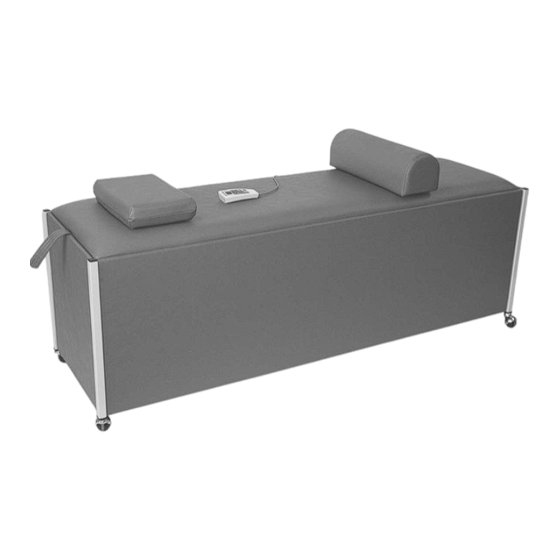
Summary of Contents for Lloyd COSMIC III
-
Page 2: Table Of Contents
Calibration Instructions..............7 Product Disclaimer................8 Table Specifications................. 8 Assisting Patients On & Off Table........... 9 Cabinet Assembly................10 Roller Carriage Assembly..............11 Travel Carriage Assembly..............12 Electrical Assembly................13 Cosmic III Wiring Diagram...............14 Hand Held Control Diagram............15 Table Serial Number... -
Page 3: Safety And Maintenance
WELCOME!! Lloyd Table Company, a proud supporter of today’s chiropractors, has established the finest line of chiropractic tables in the world. Table products unique in versatility and function, designed to meet your needs. SAFETY Concerned for a safe working and treatment environment, Lloyd Table Company asks that you follow the safety tips below. - Page 4 MAINTENANCE The following list covers all areas of the Cosmic III Inter-segmental Traction Table that should be checked, cleaned and have worn parts replaced during a preventative maintenance. Maintenance schedules are listed below and it is suggested that a maintenance routine every six (6) months should be performed by a qualified service technician.
-
Page 5: Setup Instructions
SETUP INSTRUCTION Read and complete all steps of instructions before operating your Cosmic III table. Remove Cosmic III from crate Remove the tabletop from the base of the table, by simply lifting the strap on top. Remove Contents-Bag (Hand Control, A/C Cord,and Wheels). -
Page 6: Electrical Connection
Mount Hand Control Cradle to side of table or on wall. Plug in A/C cord to back or foot end panel (See Fig. 4) Master Power Switch Fig. 4 Plug A/C cord into Grounded wall outlet. Turn table on by pressing the master power switch (See Fig. 4) Once the master power is tuned on, the massage rollers will automatically lower. -
Page 7: Operating Instructions & Functions Of The Controls
The direction in which the rollers rotate is adjustable. FUNCTIONS OF THE CONTROLS Before operating functions of the Cosmic III, the table must first be plugged into a three prong-grounding receptacle. The hand held control consists of the following switches:... - Page 8 FACTORY PRESET PROGRAM The Cosmic III is factory set with the following parameters: 1. The treatment time is preset for 10 minutes. 2. The direction of the massage rollers is rotating toward the foot (F) end of the table. 3. The massage roller carriage “TRAVEL” is turned on.
-
Page 9: Calibration Instructions
!! NOTE !! Your Cosmic III has already been calibrated at the factory. The following procedures are to be carried out by a qualified service representative & only if you recieve a “E-3” messa ge on the control head. Hand... -
Page 10: Product Disclaimer
DISCLAIMER Lloyd Table Company does not represent or warrant under any circumstances that a particular result can or will be achieved by using this product. The choice to use the product, the method or methods of use, the diagnosis of the patient’s condition and application for the patient is solely the... -
Page 11: Assisting Patients On & Off Table
ASSISTING PATIENTS ON THE TABLE * The doctor or trained staff should always place the patient on the table. Do NOT allow the patient to get on the table without help. This could cause strain to the patent or a loss of balance. -
Page 12: Cabinet Assembly
COSMIC CABINET ASSEMBLY ITEM PART N0. DESCRIPTION QTY. 43125 TOP ASS’Y 43101 SIDE ASS’Y 43118 BACK END ASS’Y 43117 SUPPORT RAIL 56485 GUIDE RIAL 43121 CROSS BRACE 43120 ELECTRICAL PLATFORM 43123 FRONT END PANEL ASS’Y 22486 FLAT HD. SHEET ROCK SCREW, #8 X 1 5/8 20010 HEX.HD. -
Page 13: Roller Carriage Assembly
ROLLER CARRIAGE ASSEMBLY ITEM PART N0. DESCRIPTION QTY. 56475 ROLLER CARRIAGE ASS’Y 56450 ROLLER STAR ASS’Y 56113 WHEEL 22690 CLEVIS PIN, 3/8 RD X 1 ¾ 22640 COTTER PIN 56489 AXLE ROD 20220 HEX HD. BOLT, 5/16-18UNC X 1 21710 FLAT WASHER, 5/16ID X .688OD 22810 BALL BEARING... -
Page 14: Travel Carriage Assembly
TRAVEL CARRIAGE ASSEMBLY 20 17 ITEM PART N0. DESCRIPTION QTY. 56465 TRAVEL CARRIAGE FRAME 24437 RUBBER WHEEL 2” 21620 FLAT WASHER, 1/4ID X 9/16OD 20022 HEX BOLT, 1/4-20UNC X 1.00 20002 SHLD BOLT, ¼-20UNC X 3/8 20795 HEX NUT, #10-24 UNC (NYLON) 22818 BALL BEARING, ROLLER CARRIAGE 21710... -
Page 15: Electrical Assembly
ELECTRICAL ASSEMBLY 12 13 ITEM PART N0. DESCRIPTION QTY. 30590 ROTATION MOTOR 30516 VIBRATION MOTOR 35215 MOTOR BRACKET 44961 POTENTIOMETER SWITCH ASS’Y 37940 SPACER, CIRCUIT BOARD 30591 HEIGHT MOTER 45205 CABLE ASS’Y, HEIGHT MOTOR 31508 CIRCUIT BOARD 38347 WIRE TERMINAL (3 POSITION) 36510 FUSE HOLDER 36172... -
Page 16: Cosmic Iii Wiring Diagram
COSMIC III WIRING DIAGRAM Page 14... -
Page 17: Hand Held Control Diagram
HAND HELD CONTROL DIAGRAM Page 15...


Need help?
Do you have a question about the COSMIC III and is the answer not in the manual?
Questions and answers