Table of Contents
Advertisement
Advertisement
Table of Contents

Related Manuals for Lloyd GALAXY ULTIMATE


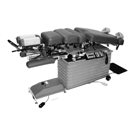
Summary of Contents for Lloyd GALAXY ULTIMATE
-
Page 3: Table Of Contents
CONTENTS OPERATIONS PAGE PARTS / ASSEMBLY PAGE Chest Cushion Assembly......31 - 32 Safety and Maintenance....... 1 - 2 T-Pelvic Cushion (Non-Rotation).... 33 Head Rest Cushion........3 - 7 Telescoping T-Bar........34 Chest Cushion..........8 Ankle Rest Adjustable Height....35 Manual &... -
Page 4: Safety And Maintenance
WELCOME!! Lloyd Table Company, a proud supporter of today’s chiropractors, has established the finest line of chiropractic tables in the world. Table products unique in versatility and function, designed to meet your needs. SAFETY Concerned for a safe working and treatment environment, Lloyd Table Company asks that you follow the safety tips below. - Page 5 MAINTENANCE The following steps should be performed on a regular basis to maintain your Lloyd table in a smooth operating condition and to assure its long life and top quality appearance. An initial inspection and periodic future inspections should be made to insure that nuts and bolts have not loosened in shipping or during daily operations.
-
Page 6: Head Rest Cushion
The following sections provide explanations on the operation of your Lloyd table. All references to right and left, will be in relationship to your view, as you face table from the foot end. All references to the front will refer to the head end of the table. - Page 7 Standard - Deluxe Head To Elevate the Head Cushion The head cushion is assisted by a gas shock in raising the cushion. With a hand supporting the head cushion, turn the Elevation Knob (No. 2) on either side of the table upward to unlock.
- Page 8 Optional - Deluxe Head with Drops #8 Tension Knob #7 Cocking Handle #9 Selector Knob (Right Side of Table) Operating the Straight / Toggle Drop: CAUTION: THE DROP CUSHION TENSION SHOULD BE CHECKED AND TESTED BEFORE ADJUSTING A PATIENT. NOTE - DROP SHOULD BE IN DOWN / DEACTIVATED POSITION BEFORE MOVING SELECTOR KNOB (NO.
- Page 9 Optional - Total Dimension Flexion Head Left Side #8 Flexion Assist Handle #1 Selector Knob #7 Face Opening Lever #2 Cocking Handle #6 Rotation Release Knob #3 Lateral Side Bending Release Knob #5 Flexion / Tilt Knob #4 Traction Release Knob Forward &...
- Page 10 Optional - Total Dimension Flexion Head WARNING: THE FOLLOWING CERVICAL OPERATIONS ARE ONLY TO BE OPERATED BY A PROFESSIONAL PRACTITIONER, EDUCATED IN THE PROCEDURE OF FLEXION-DISTRACTION AND TRACTION, ON THE SPINE. Lateral Side Bending To unlock the Lateral Side Bending Feature rotate the Lateral Side Bending Release Knob (No.
-
Page 11: Chest Cushion
Chest Cushion The chest cushion is designed to accommodate large and small abdomen patients, along with the versatility of being a stationary or floating cushion. Optional - Drop Chest & Lumbar Shown Below #3 Spring Breakaway Tension Knob #1 Adjustable Chest #2 Spring Breakaway Handle Release Knob... -
Page 12: Manual & Automatic Drops
Chest Cushion - Manual Drops #2 Tension Control Knob #1 Cocking Handle Chest & Lumbar Drop - Manual Cocking the Drop Chest or Lumbar Cushion Pull up on the Cocking Handle (No. 1) to cock the desired drop cushion. Adjust the tension on either side by turning the Tension Control Knob (No. 2) Right side: Clockwise - Decreases Tension Counterclockwise - Increase Tension Left Side:... - Page 13 Automatic Cocking Drops #1 Automatic Drop Selector Knob Cervical (Head Cushion) Drop - Automatic To Cock the Cervical (Head Cushion) Drop: Rotate the selector knob (No. 1) to “C” to select the Cervical (Head Cushion) drop. Step on the white strip to activate the auto cocking drop. CAUTION: THE DROP CUSHION TENSION SHOULD BE CHECKED AND TESTED BEFORE ADJUSTING PATIENT.
-
Page 14: Head & Chest Extension / Retraction
Automatic Cocking Drops To Cock the Pelvic Cushion Drop: Rotate the selector knob (No. 1) to “P” to select the Pelvic drop. Step on the white strip to activate the auto cocking drop. CAUTION: THE DROP CUSHION TENSION SHOULD BE CHECKED AND TESTED BEFORE ADJUSTING PATIENT. -
Page 15: Pelvic Cushion - Flexion
Pelvic Cushion Flexion - Distraction The Pelvic section is designed with the capability of Traction, Lateral Side Bending, Flexion, and optional rotation #1 Up Speed Control #2 Down Speed Control #3 Flexion Lock Handle (Yellow) #4 Flexion Pressure Gauge WARNING: THE FOLLOWING PELVIC OPERATIONS ARE ONLY TO BE OPERAT- ED BY A PROFESSIONAL PRACTITIONER, EDUCATED IN THE PROCEDURE OF FLEXION - DISTRACTION AND TRACTION, ON THE LOWER BACK AND SPINE. - Page 16 Pelvic Cushion Flexion - Distraction Manual Flexion BEFORE ENGAGING PELVIC FLEXION, BE SURE THE PRESSURE IS PROPERLY ADJUSTED TO SUPPORT PATIENT (SEE FLEXION PRESSURE PAGE 12). Turn the Yellow Flexion Lock Handle (Page 12, No. 3) up to engage manual flexion. Simply push down on the pelvic, ankle cushion, or optional T-Bar to achieve flexion.
- Page 17 Pelvic Cushion Flexion - Distraction #11 Delay On/Off Switch #7 Pelvic Retraction #8 Pelvic Extension #9 Flexion Height Adjustment - Up #10 Flexion Height Adjustment #6 Reset Button - Down #2 Counter Load Button #4 Auto Flexion Start Button #5 Auto Flexion Stop Button #12 Patient Stop Switch #3 Counter Display...
- Page 18 Pelvic Cushion Flexion - Distraction Adjusting the Depth of the Up & Down Position ALWAYS CHECK THE UP/DOWN SPEED OF THE PELVIC CUSHION BEFORE ADJUSTING THE PATIENT. SEE FLEXION SPEED CONTROL PAGE 12 & 13. Fig. #1 Fig. #2 Fig. #3 Fig.
-
Page 19: Pelvic Lateral Side Bending
Pelvic Cushion Flexion - Distraction Delay Off/On Switch Up Delay Down Delay Up Delay Feature The Up delay adjustment knob controls the amount of time the pelvic cushion stays in the highest set position from 0 to 30 seconds. Simply turn the knob clockwise to increase the delay. Down Delay Feature The down delay adjustment knob controls the amount of time the pelvic cushion stays in the lowest set position from 0 to 30 seconds. -
Page 20: Pelvic Rotation & Telescoping T-Bar
Pelvic Rotation & T - Bar Telescoping T-Bar #1 Rotation Lock Handle Pelvic Rotation (Optional) To Unlock the Pelvic Rotation Support the edge of the pelvic cushion. Pull up and slide the Rotation Lock Handle (No. 1) towards the rear of the table to unlock. To lock the Pelvic Rotation Place the Pelvic Cushion into it’s horizontal position. -
Page 21: Ankle Rest & Lumbar Extension
Ankle Rest #2 Vertical Lock Lever #1 Horizontal Lock Knob Ankle Rest Adjustment To Extend or Retract the Ankle Rest Loosen the Horizontal Lock Knob (No. 1) and slide the cushion to the desired length. Once the cushion is adjusted, tighten the lock knob. Table will not tilt with ankle rest cushion extended see page 19. -
Page 22: Control / Indicator Box
Control / Indicator Box Ankle Rest Pelvic Flexion Pelvic Extension Side Bending Cushion Extension Button Indicator Box The four indicator lights on the control box represent a safety switch for four different operations. When any of the lights are illuminated, the table will not hylo up or down until that particular function(s) is secured in position and all lights are out. -
Page 23: Tilt Safeguard
Control / Indicator Box Ankle Rest Light The ankle rest safety switch is secured, by sliding cushion forward and locking into position (Page 18). Cushion Extension Button The Cushion Extension switch is used to move head, chest, and pelvic cushions at once. This allows the cushions to maintain the same patient spacing, while shuttling the patient forward and to provide foot clearance with the foot plate when raising the table to verticle position (tilted). -
Page 24: Foot Pedal Control
Master Power Switch Master Power Switch Fuse Holder The Master Power Switch is located on the front left side of the base frame. The switch is operated by pushing on the left or right side, marked with a zero or dash. ON is indicated with a dash (-) B. -
Page 25: Height Select Panel
Height Select Panel #1 Height Select #2 Auto / Manual #3 Lower (Elv) / (Tilt) Switch #4 Lower (Tilt) / #5 Beeper / Mute (Elevate) Switch Switch Height Select (No. 1) The height select panel consists of nine height select buttons whereby the operator can preselect a desired height. The buttons range from 22 to 38 inches, at two inch increments. -
Page 26: Tilt Frame
TILT FRAME ASS’Y Page 23... - Page 27 TILT FRAME ASS’Y ITEM PART N0. DESCRIPTION QTY. 58685 TILT FRAME ASS'Y 40030 ARM REST ASS'Y (RH) 22031 SCREW,MACH, SOC HD, FLAT, ¼-20 UNC X 1 ¼ 55574 GUIDE RAIL 22085 HEX. HD. LAG SCREW, ¼ X 3.00 58790 GUIDE ROD 40010 ARM REST CUSHION (LH) 21110...
-
Page 28: Scissor Frame
SCISSORS FRAME ASS’Y ITEM PART N0. DESCRIPTION QTY. 58500 SCISSORS BRACE FRAME ASS’Y 58515 SCISSORS YOKE FRAME ASS’Y 58498 CYLINDER SUPPORT BLOCK 20208 SOCKET HEAD BOLT, ½-13 UNC SHOU 5/8 X 5/8 22792 BEARING, ROLLER, 5/8 ID 20056 SOCKET HEAD BOLT, ¼-20 UNC X 2 ½ 58653 REAR YOKE ASS’Y 22230... -
Page 29: Base Frame
BASE FRAME ASSEMBLY ITEM PART N0. DESCRIPTION QTY. 58672 FRONT CROSS BAR 58671 MIDDLE CROSS BAR 58644 GUIDE ROD 22853 BUSHING, 1 ¼ ID X 1 13/32 OD 55982 SLIDE BLOCK, 1 ¼ X 2.00 X 2.00 (LH) 56113 WHEEL 56114 BUSHING, ½... -
Page 30: Deluxe Head Frame
DELUXE HEAD FRAME ASS’Y ITEM PART N0. DESCRIPTION QTY. 56051 FASTER PLATE ASS’Y 57221 ADJUSTMENT ARM 55929 CENTER BAR 21616 PLASTIC FLAT WASHER, ¼ ID X ¾ OD 24020 HANDLE 22050 RD. HD. MACHINE SCREW, ¼-20 UNC X 2 ½ 21450 HEX. -
Page 31: Deluxe Head Cushions
DELUXE HEAD CUSHION ASS’Y ITEM PART NO. DESCRIPTION 40110 CUSHION, HEAD - LEFT HAND 40130 CUSHION, HEAD - RIGHT HAND 29999 HEADREST PAPER 30400 BLOCK, SLIDE, FRONT, FWD DROP HEAD 22009 OVAL HD. MACHINE SCREW, #10-24 NC X 1 1/2 57174 SPACER, 3/16 ID X ½... -
Page 32: Deluxe Head I-Frame
I-FRAME ASSEMBLY DELUXE & FROWARD MOTION HEAD Page 29... - Page 33 I-FRAME ASSEMBLY DELUXE & FROWARD MOTION HEAD ITEM PART N0. DESCRIPTION QTY. 55941 I-FRAME ASS’Y 50872 GUIDE ROD, ½ RD. X 7 7/8 30296 PRESSURE CYLINDER, F/M 89, 50# 30297 PRESSURE CYLINDER, DELUXE HD. 40# 24186 TENSION KNOB 56019 GEAR RACK 56002 SUPPORT PIN, 5/16 RD.
- Page 34 CHEST CUSHION ASS’Y SPRING BREAKAWAY Page 31...
-
Page 35: Chest Cushion Assembly
CHEST CUSHION ASSEMBLY SPRING BREAKAWAY ITEM PART N0. DESCRIPTION QTY. 40210 CUSHION, CHEST - STANDARD 40230 CUSHION, CHEST - WIDE 40290 CUSHION, EXTENSION - STANDARD 40291 CUSHION, EXTENSION - WIDE 51010 BRACE, CUSHION (LH) 51030 BRACE, CUSHION (RH) 20022 BOLT, HEX HEAD, ¼ - 20 NC X 1 20361 BOLT, HEX HEAD, 3/8 - 16 NC X 1 ¾... -
Page 36: T-Pelvic Cushion (Non-Rotation)
T-PELVIC ASSEMBLY NON-ROTATION ITEM PART N0. DESCRIPTION QTY. 40292 PELVIC CUSHION ASS’Y 22888 CAP BUSHING, BRASS 58542 GUIDE FRAME ASS’Y 58527 CARRIAGE FRAME ASS’Y 22850 BUSHING, NYLON, ¾ ID X 7/8 OD X ¾ 22615 CLEVIS PIN, 5/16 X 2 22639 COTTER PIN, 3/32 X ½... -
Page 37: Telescoping T-Bar
T-BAR ASSEMBLY ITEM PART N0. DESCRIPTION QTY. 58406 T-HANDLE, (SHORT) 58405 T-HANDLE, (ANGLED) 58400 GUIDE TUBE, (SHORT) 58398 GUIDE TUBE, (ANGLED T-BAR) 58411 MOUNTING BLOCK 58405 LOCK ROD 20507 HEX HD. BOLT, 7/16-14 UNC X 3 ¼ 20503 HEX HD. BOLT, 7/16-14 UNC X 1 ¼ 21290 HEX NUT, 7/16-14 UNC 20054... -
Page 38: Ankle Rest Adjustable Height
ANKLE REST ADJUSTABLE HEIGHT ITEM PART N0. DESCRIPTION QTY. 40410 ANKLE REST CUSHION 56507 BASE PLATE 30774 COMPRESSION SPRING 56519 LOCK HANDLE 56525 GUIDE BLOCK 56518 GUIDE ROD 22468 SCREW, WOOD, RD HEAD, #10 X 7/8 24236 GUARD, TEE HANDLE 22610 PIN, CLEVIS, 5/16 X 7/8 56539... -
Page 39: Cover & Bellows
COVER & BELLOWS ASSEMBLY ITEM PART N0. DESCRIPTION QTY. 58665 TOP BELLOWS FRAME 699220 BELLOWS COVER 58758 COVER CLAMP 21420 HEX NUT, #8-32UNC 21510 FLAT WASHER, 3/16ID 699230 ELECTRICAL COVER 21979 PAN HD SCREW, #6-32UNC X 5/8 22450 RD HD SCREW, #8 x 5/8 697335 CYLINDER COVER 699235... -
Page 40: Hydraulics
HYDRAULICS Page 37... - Page 41 HYDRAULICS ITEM PART N0. DESCRIPTION QTY. 623445 PUMP, MOTOR & BLOCK ASS'Y (Non- Auto) 623446 PUMP, MOTOR & BLOCK ASS'Y (Auto Drop & Auto Flexion) 623451 PUMP, MOTOR & BLOCK ASS'Y (Auto Drop w/o Auto Flexion) 45530 HOSE, HYDRAULIC, ¼" X 50 (Tilt Cylinder) 45366 HOSE, HYDRAULIC, 3/16 X 56 ½...
- Page 42 ULTIMATE HYDRAULIC ASSEMBLIES # 623445 - Non - Auto Pump, Motor & Block Assembly # 30495 - Pump & Motor, 115 v # 23130 - Fitting, 90 Degree, 1/8 Male - Female # 23155 - Fitting, 90 Degree, More # 4 - 1/4 # 23336 - Nipple, Pipe, 5"...
-
Page 43: Manintenance Schedual
For your convenience a table maintenance schedule has been provided to keep track of all repairs and parts purchases. Date Part Number ***Always include the table’s serial number when calling Lloyd Table Company Service Department*** Telephone: 319-455-2110 Toll Free: 800-553-7297 Fax: 319-455-2166 Email: service@lloydtable.com... -
Page 44: Electrical Assembly
ELECTRICAL CABLE ASS’Y # 44218 ITEM DESCRIPTION ITEM DESC 110 VOLT 100 VOLT 220 VOLT -HS (HEIGHT SELECT) FUSE # 36335 # 36341 # 36334 -AF (AUTO FLEXION) 24 V 1 AMP 2 AMP 0.8 AMP -2 (FOOT SWH HARNESS) -5 (SEQUENCE BOX) FUSE # 36235... - Page 45 ELECTRICAL ITEM PART N0. DESCRIPTION QTY. 45040 CIRCUIT BOARD ASS'Y, CONTROL LOGIC DRIVER 44081 PEDAL ASS'Y, DIRECTION CONTROL 44082 PEDAL ASS'Y, FLEXION CONTROL 44083 TAPE SWITCH, 36" ( AUTO DROP ONLY 44084 TAPE SWITCH, 12" ( AUTO DROP ONLY W/ONE DROP 45038 CIRCUIT BOARD ASS'Y, HEIGHT SELECT 52037...
-
Page 46: Straight Drop Head
STRAIGHT DROP HEAD ASS’Y Items 49, 50, 51, 52, 53 and 54 are require only for Auto Cocking Cervical Tables. Page 43... - Page 47 STRAIGHT DROP HEAD ASSEMBLY ITEM PART N0. DESCRIPTION QTY. 56011 FASTER PLATE ASS’Y, ’89 STRAIGHT DROP HD 57201 OUTSIDE DROP FRAME ASS’Y, ’89 FM HEAD 55850 TEE WEDGE ASSEMBLY 22017 SCREW, MACHINE, FLAT HEAD, ¼ - 20 UNC X ½ 55929 CENTER ROD ASSEMBLY 21616...
-
Page 48: Forward Motion Drop Head
FORWARD MOTION HEAD FRAME ASS’Y NOTE: ITEMS 28, 33, 34, 35, 36, 37, 38 & 40 ARE USED ONLY FOR TABLES WITH AUTO COCKING CERVICAL. Page 45... - Page 49 FORWARD MOTION HEAD FRAME ITEM PART NO. DESCRIPTION 56059 OUTSIDE DROP FRAME ASS’Y 57201 OUTSIDE HEAD FRAME ASS’Y 55850 TEE WEDGE 57221 ADJUSTMENT ARM, HEAD CUSHION 57175 LINKAGE BAR, 1/8 X 1/2 X 3 9/16 21995 PAN HD. MACHINE SCREW, #10-24 NC X 1/2 22860 BUSHING, 3/16 ID X 1/4 OD 30722...
-
Page 50: Flexion Head Cushion Assembly
FLEXION HEAD CUSHION ASSEMBLY Page 47... - Page 51 FLEXION HEAD CUSHION ASSEMBLY ITEM PARTN0. DESCRIPTION QTY. 40980 HEAD CUSHION ASSEMBLY (RH) 40979 HEAD CUSHION ASSEMBLY (LH) 57155 GUIDE BRACKET 57156 GUIDE BRACKET 22003 SCREW, MACHINE, PAN HEAD, #10 – 24 UNC X ¾ 55825 INSIDE HEAD FRAME 57174 SPACER, FORWARD DROP, 3/16 X 1/2 X 5/8 22860 BUSHING, 3/16 ID X ¼...
-
Page 52: Flexion Head - Shuttle Assembly
FLEXION HEAD SHUTTLE ASS’Y Page 49... - Page 53 FLEXION HEAD SHUTTLE ASS’Y ITEM PART N0. DESCRIPTION QTY. 55750 SHUTTLE ASS’Y 55787 LINKAGE ROD 22740 SWIVEL JOINT END 22689 SHEARPROOF PIN, ¼ 1 1/4 55757 ROTATION CYLINDER 55959 PLUNGER 30740 COMPRESSION SPRING 24186 ADJUSTMENT HANDLE 21210 HEX NUT, 3/8-16 UNC 20199 SHOULDER BOLT, 5/16-18 UNC X ½...
-
Page 54: Flexion Head - Slide Frame
FLEXION HEAD SLIDE FRAME ASSEMBLY Page 51... - Page 55 FLEXION HEAD SLIDE FRAME ASSEMBLY ITEM PART N0. DESCRIPTION QTY. 55778 SLIDE BRACKET ASS’Y 55794 LOCK FRAME ASS’Y 22865 BUSHING, ¼ ID X 5/16 OD 22657 ROLL PIN 1/8 X 3/8 22660 LOCK KNOB 22031 SOCKET HD SCREW, ¼-20 UNC X 1 ¼ 30750 COMPRESSION SPRING 55762...
-
Page 56: Flexion Head Rotation Block
ROTATION BLOCK ASSEMBLY FLEXION HEAD Item 56 - Flexion Handle Kit #634020 Part No. Description 55838 Handle Tube 55836 Side Ass’y (RH) 55837 Side Ass’y (LH) 24023 Handle Grip 24024 Adjustable Thumb Handle 20188 Socket Hd. Bolt #10-24 22410 Pan Hd. Screw Page 53... - Page 57 ROTATION BLOCK ASSEMBLY FLEXION HEAD ITEM PART N0. DESCRIPTION QTY. 55777 ROTATION FRAME ASSEMBLY, FLEXION HEAD 55773 PIVOT ARM ASSEMBLY, FLEXION HEAD 55963 STABILIZER BRACKET ASS’Y, SWIVEL HEAD 55788 GUIDE ROD, CRADLE ASS’Y, FLEX HD, 3/8 RD X 7 5/8 21610 WASHER, FLAT PLASTIC, 0.26 ID X ½...
-
Page 58: T -Drop Chest Ass'y
T- DROP CHEST ASS’Y FULL CUSHION Page 55... - Page 59 T- DROP CHEST ASS’Y FULL CUSHION ITEM PART N0. DESCRIPTION QTY. 40235 CHEST CUSHION ASS’Y 57433 FRONT TEE WEDGE ASS’Y 57429 REAR TEE WEDGE ASS’Y 20022 HEX HD BOLT, ¼-20UNC X 1.00 20350 HEX HD BOLT, 3/8-16UNC X 1 ¼ 57435 SIDE RAIL 21210...
-
Page 60: Drop Chest & Lumbar
DROP CHEST & LUMBAR CUSHION Note: Item #40 is used only on table’s with Breakaway Chest. Note: For Detail Parts on Breakaway Chest refer to Deluxe Chest Cushion (pages 31 & 32). Page 57... - Page 61 DROP CHEST & LUMBAR CUSHION ITEM PART N0. DESCRIPTION QTY. 57309 CHEST & LUMBAR FRAME ASSEMBLY 40510 CUSHION, DROP CHEST 40530 CUSHION, DROP LUMBAR 57330 MOUNTING PLATE ASS'Y 57416 COCKING HANDLE BAR (RH) 57436 COCKING HANDLE BAR (LH) 30420 DROP BLOCK, ALUMINUM (LH) 30426 SHAFT, STEEL 22710...
- Page 62 ROTATION CHEST FRAME ASS’Y 20 55 Page 59...
-
Page 63: Rotation Chest Frame Assembly
ROTATION CHEST FRAME ASSEMBLY ITEM PART N0. DESCRIPTION QTY. 55997 I-FRAME ASS'Y, ROTATION CHEST 57303 GEAR TRAIN FRAME ASS'Y, SWIVEL YOKE 57401 BLOCK, GUIDE, SWIVEL CHEST ASS'Y, 1 ¼ X 1 ½ X 2 ¾ 20024 BOLT, SOCKET HEAD, ¼ - 20 NC X 1 ¼ 57394 BLOCK, LOCKING ROD, SWIVEL CHEST, 7/16 X 5/8 X 1 7/16 20023... - Page 64 DROP CHEST & LUMBAR CUSHION Note: Item #40 is used only on table’s with Breakaway Chest. Note: For Detail Parts on Breakaway Chest refer to Deluxe Chest Cushion (pages 22 & 23). Page 61...
-
Page 65: Rotation Chest Cushion Assembly
ROTATION CHEST CUSHION ASSEMBLY DROP DORSAL & LUMBAR ITEM PART N0. DESCRIPTION QTY. 57308 FRAME ASS'Y, ROTATION CHEST 40510 CUSHION, DORSAL 40530 CUSHION, LUMBAR 40230 CUSHION, EXTENSION 57384 TONGUE, EXTENSION, 9/16 RD X 9 3/8 22030 SCREW, MACH, FLAT HEAD, ¼ - 20 NC X 1 56202 GUARD, CUSHION 22460... -
Page 66: T -Drop Pelvic (Non Rotation)
T-DROP PELVIC ASS’Y NON-ROTATION 32 33 Page 63... - Page 67 T-DROP PELVIC ASS’Y NON-ROTATION ITEM PART N0. DESCRIPTION QTY. 40307 PELVIC CUSHION ASS’Y 56493 STRIKER PLATE 22469 FLAT HD WOOD SCREW, #10 X 7/8 21210 HEX NUT, 3/8-16UNC 56359 COCKING ARM 22810 ROLLER BEARING 20350 HEX HD BOLT, 3/8-16UNC X 1 ¾ 22250 SET SCREW, 5/16-24UNF X ½...
-
Page 68: T -Drp Pelvic (Rotation)
T-DROP ROTATION PELVIC ASSEMBLY Page 65... - Page 69 T-DROP ROTATION PELVIC ASSEMBLY ITEM PART N0. DESCRIPTION QTY. 40307 PELVIC CUSHION ASSEMBLY 56493 STRIKER PLATE 22469 FLAT HD WOOD SCREW, #10 X 7/8 21210 HEX NUT, 3/8-16UNC 56359 COCKING ARM 22810 ROLLER BEARING 20350 HEX HD BOLT, 3/8-16UNC X 1 ¾ 22250 SET SCREW, 5/16-24UNF X ½...
-
Page 70: Hydraulics - Auto Drops
HYDRAULIC ASSEMBLY AUTO T-DROPS Cocking Cylinder item #28, specify fitting type when ordering. Page 67... - Page 71 HYDRAULIC ASSEMBLY AUTO T-DROPS ITEM PART N0. DESCRIPTION QTY. 623452 MOTOR &PUMP 45270 HYD. HOSE 3/16 X 17 ½ (Pelvic only) 45373 HYD. HOSE 3/6 X 66 (All Auto) 23047 COUPLER MALE ¼” JIC (Pelvic only) 45362 HYD. HOSE, 3/16 X 52 ½ (Pelvic only) 31010 SELECTOR VALVE 23130...
-
Page 72: Electronic Diagrams
SAFETY LIGHT PANEL Page 69... - Page 73 ULTIMATE CABLE JUNCTION BOX Page 70...
- Page 74 ULTIMATE CABLE JUNCTION BOX Page 71...
- Page 75 ULTIMATE CABLE JUNCTION BOX Page 72...
- Page 76 ULTIMATE HARNESS CONNECTIONS Viewed from wire side of connector Cable Group 1 Wires: Retract Pelvic / Extend Table (Black) Pelvic Extended Safety Switch (Brown) Side Bending Safety Switch (Red) Ankle Rest Safety Switch (Red-Black) Pelvic Flexion Safety Switch (Red-Yellow) Extend Pelvic (from Auto Flex Panel) (Red-Green) Extend Table (Chest Extension) (Orange) Ground (Yellow) Ground (Green)
Need help?
Do you have a question about the GALAXY ULTIMATE and is the answer not in the manual?
Questions and answers
Loyd High Low table with hydraulic drops and lift and suddenly lost hydraulics lift and raising the table, looking for maybe a breaker or insight for help
The hydraulic lift on a Lloyd Galaxy Ultimate high-low table could fail due to the following reasons:
1. Low Hydraulic Fluid Level: If the fluid level in the pump’s reservoir tank is low, the lift may not function properly.
Fix: Check the fluid level yearly and refill with the recommended hydraulic fluid (Lubriplate HO1 or hydraulic jack oil).
2. Oil Leaks or Drips: Leaks in the hydraulic system can reduce the effectiveness of the lift.
Fix: Perform periodic inspections for oil leaks and repair or replace faulty components.
3. Improper Maintenance: Lack of lubrication on frame pivot points and sliding mechanisms could lead to operational issues.
Fix: Lubricate these parts every six months (do not lubricate friction locks).
4. Electrical Issues: If the directional foot pedal or power system is malfunctioning, the lift may fail.
Fix: Ensure the power switch is turned on and inspect the fuse holder. Replace blown fuses with the same size rating after unplugging the power cord.
Regular maintenance and inspections are essential to prevent hydraulic lift failure.
This answer is automatically generated