Table of Contents
Advertisement
Quick Links
Specifications
Input Voltage:
Frequency:
Voltage Regulation:
Output Voltage Range:
Maximum Forcing Output:
Rated Continuous Output:
Minimum Field Resistance:
Min Residual Build up Voltage:
Under Frequency Protection:
Physical Size:
Weight:
Integrated Control Module:
Repairable:
Internal Protection:
External Voltage Adjustment:
System Operating Indicator:
Optional External Controls
Integrated 0-10VDC / 4-20mA Interface:
208 - 240vac
50 or 60 Hz
+/- .25% From NL to FL
0-210vdc @ 240vac input
210vdc @ 30adc
125vdc @ 25adc
7Ω @ 210vdc output
5vac
Yes, VPH reduction
10 x 10 x 4 in.
4 lb.
PCMG-B
Yes
Fuses, cartridge type
Yes
Yes
Yes
Yes
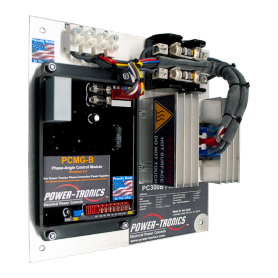
PC300B
Phase Control
The Power-Tronics PC300B Phase control
is a self-contained complete Phase control
designed for continuous operation at up to
210vdc at 30Adc!
The PC300B is uniquely designed to sit in
a compact footprint while being passively
convection cooled for a long service life.
Because of its unique modular design, the
PC300B minimizes downtime should a
repair ever be necessary! All serviceable
parts are easily removable without the
need to remove the chassis from the
mounting cabinet or tray. The compact
design allows a wide variety of installation
methods, including installations where
space is at a premium.
Over 30 years of field use and design
refinement makes the PC300B a time-
proven design, utilizing high-reliability
components, and a unique modular design
to simplify repair. The PC300B is
designed to provide a lifetime of service
and is specifically built to minimize failures
and potential downtime!
The PCMG-B control module includes an
internal 0-10VDC or 4-20mA interface
module to allow a wide variety of VAR, PF,
or other PLC controls to remotely control
the unit. An optional motorized
potentiometer allows remote operation by
dry contact switching or older pulsed-DC
control schemes.
The PC300B Phase control is the latest
upgrade to the PC300B series of phase
controls.
© 2021 Power-Tronics, Inc.
Advertisement
Table of Contents

Subscribe to Our Youtube Channel
Related Manuals for Power-Tronics PC300B


Summary of Contents for Power-Tronics PC300B
- Page 1 Phase control designed for continuous operation at up to 210vdc at 30Adc! The PC300B is uniquely designed to sit in a compact footprint while being passively convection cooled for a long service life. Because of its unique modular design, the...
-
Page 2: Table Of Contents
Fully Automatic Remote Adjustment Wiring Diagram:..........11 Automatic / Manual Selectable Remote Adjustment Wiring Diagram:....12 Initial Setup and Commissioning:................13 Bench Check Procedures:...................14 Installation Warranty Form:..................15 Product Warranty Certificate:..................16 For Technical Support: Visit our website at: www.power-tronics.com Call Us at: (830) 895-4700... -
Page 3: Introduction And Functional Description
(It can give a false reading!) Functional Description The PC300B Phase Control is the result of over 30 years of engineering efforts and offers high- demand features at a competitive price point. The PC300B is a proven design and is engineered to greatly simplify setup while offering extreme reliability. -
Page 4: Determining Application Sizing
PC300B is the correct product for your application. To determine if the PC300B is the correct product for your load you need to know any two of the following 3 specifications from the rating plate of your load:... - Page 5 If you show more than 1% difference in reading your device has brush and ring contact problems and will need cleaning or maintenance before installing the PC300B. Failure to correct brush and ring contact problems will result in severe damage to the phase control as well...
-
Page 6: Included Parts & Accessories
Included Parts & Accessories The PC300B Static Exciter includes the following parts and accessories to ensure a quick and easy installation: Included Parts List: • Vibration Isolators Qty: 4 • ¼-20 Self-Locking Nuts Qty: 8 • #16-14AWG Compression Terminal Qty: 1 •... -
Page 7: Mounting Dimensions & Chassis Ground
Chassis Should Be Grounded For Safety!!! Use Supplied Compression Terminal And Bellville Washer Provided In Accessories Kit Attach to Bottom Right Mounting Point. Torque to 125 in•lbf (15N•M) For Technical Support: Visit our website at: www.power-tronics.com Call Us at: (830) 895-4700... -
Page 8: Input Power & Field Connection Diagram
Suitable for use on Electrical Generators Without a Suitable Voltage Control Source!!! The PC300B is a Full-Wave rectified phase control, which allows a maximum of 210VDC @ 240VAC or 105VDC @120VAC at 30 ADC continuous. This product is typically used on slip-ring synchronous motors or on inductive loads with full load control field voltages of 125VDC or less and full load exciter field amperage between 5 and 30ADC. -
Page 9: Pcmg-B Control Module
Input for 0-10V or 4-20mA Signal V/MA Jumper: Installed for 4-20ma Signal Remove for 0-10V Signal Power Base Voltage V/MA Jumper Status Trim Control Lamp 25 Turn Pot! For Technical Support: Visit our website at: www.power-tronics.com Call Us at: (830) 895-4700... -
Page 10: Standard Control Wiring Diagram
Standard Control Wiring Diagram This wiring diagram shows the default control wiring configuration for the PC300B and assumes manual control with a remote potentiometer. Power wiring is shown on Page 8. NOTE: It is not necessary to jumper terminals R1 and R2 if not... -
Page 11: Fully Automatic Remote Adjustment Wiring Diagram
Fully Automatic Remote Adjustment Wiring Diagram This wiring diagram shows ONLY the control wiring configuration for fully-automatic Remote Control of the PC300B. Control wiring is shown on Page 10. 0-10VDC 4-20mA Control Signal NOTE: Purple and Orange Jumpers are supplied in... -
Page 12: Automatic / Manual Selectable Remote Adjustment Wiring Diagram
Automatic / Manual Selectable Remote Adjustment Wiring Diagram This wiring diagram shows ONLY the control wiring configuration for selectable fully-automatic or manual Remote Control of the PC300B. Control wiring is shown on Page 10. 0-10VDC Switch Position: 4-20mA Control Signal Automatic é... -
Page 13: Initial Setup And Commissioning
Install the PC300B and wire according to the correct wiring diagram and control wiring diagram (Pages 8-12). If installing the PC300B on a load containing slip rings and brushes, verify that the brushes and brush riggings are isolated, ungrounded, and connected ONLY to the PC300B. -
Page 14: Bench Check Procedures
Install a temporary jumper wire between terminals G1 and G2 on the PCMG-B Control Module. Input 208-240VAC fused at no more than 5A into the PC300B. The test light should be OFF. Attach a 100KΩ potentiometer to R1 and R2 terminals on the PCMG-B Control Module. -
Page 15: Installation Warranty Form
Rated KVA: Primary Load (Please Explain): Repair/Warranty Request Information Company Name: Contact Person: Telephone Number: Email Address: Ship-To Address (City, State, Zip, Country): Problem Description/History (Please be detailed!!!): For Technical Support: Visit our website at: www.power-tronics.com Call Us at: (830) 895-4700... -
Page 16: Product Warranty Certificate
These problems should be protected with external devices provided by the customer such as fuses, surge suppressors, over/under voltage and frequency controls. Power-Tronics, Inc., warranties only parts and workmanship of this product for a period of 3 years from the original date of purchase from Power-Tronics, Inc. Under warranty, Power- Tronics, Inc.
Need help?
Do you have a question about the PC300B and is the answer not in the manual?
Questions and answers