Table of Contents
Advertisement
Quick Links
Specifications
Input Voltage:
Frequency:
Output Voltage:
Maximum Continuous Output:
Maximum Forcing Output:
Minimum Field Resistance:
Physical Size:
Weight:
Repairable:
© 2012 Power-Tronics, Inc.
208-240vac
N/A
0-105vdc @ 240vac input
90adc
100adc
1.05Ω @ 105vdc output
10 x 10 x 8 in.
8 lbs
Yes
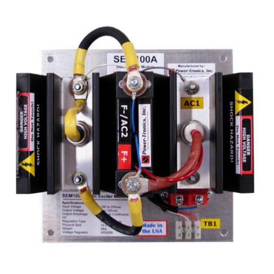
SEM100A
Static Exciter Module
The Power-Tronics SEM100A Static
Exciter Module is a self-contained
external rectifier assembly for all
Power-Tronics XR and UVR series
voltage regulators. The SEM100A
Static Exciter Module allows a
standard Power-Tronics voltage
regulator to control exciter fields with
current requirements up to 100 amps
DC at 105VDC!
The SEM100A is a unique design,
intended to offer the capacity of a full
static exciter while reducing its
physical footprint for installations with
space restrictions.
The SEM100A is a very robust design
and is intended to operate for a
lifetime. However, should repair ever
be necessary, the SEM100A is
extremely simple to repair, minimizing
downtime!
The SEM100A Static Exciter is
compatible with all Power-Tronics
UVR, XR, and certain older VR series
voltage regulators, as well as the
Power-Tronics PC500X, UVR500PC,
and XR500PC phase controllers!
Advertisement
Table of Contents

Related Manuals for Power-Tronics SEM100A


Summary of Contents for Power-Tronics SEM100A
- Page 1 The SEM100A is a very robust design and is intended to operate for a lifetime. However, should repair ever Specifications...
-
Page 2: Table Of Contents
Table of Contents Introduction and Functional Description:..............3 Determining Application Sizing:...................4 Hookup Diagram:......................6 Parallel Hookup Diagram:....................7 Initial Setup and Commissioning:.................8 Optional Power-Tronics Add-On Modules:..............9 Application Troubleshooting:..................10 Bench Check Procedures:...................11 Installation Warranty Form:..................12 Product Warranty Certificate:..................13 © 2012 Power-Tronics, Inc. -
Page 3: Introduction And Functional Description
(It can give a false reading!) Functional Description The SEM100A Static Exciter Module has a proven track record of over 20 years of extreme reliability and robustness. It offers an inexpensive and unique way to upgrade a standard voltage regulator to a reduced size static exciter with a minimum of connections and a minimum of installation space. -
Page 4: Determining Application Sizing
SEM100A is the correct product for your application. To determine if the SEM100A is the correct product for your generator you need to know any two of the following 3 specifications from the rating plate of your generator:... - Page 5 R is your measured field resistance. Using the values you just measured and calculated, see the chart on the previous page to determine whether the SEM100A is the correct product for your application. © 2012 Power-Tronics, Inc.
-
Page 6: Hookup Diagram
For use on 480V systems, either connect the SEM100A to the winding center taps T7 and T8 or use a 480-240V step-down transformer. Connecting the input of the SEM100A to 2 different legs of the generator as shown in the diagram below will result in greater regulation accuracy than when connecting line- neutral. -
Page 7: Parallel Hookup Diagram
Parallel Connection Diagram To use the SEM100A Static Exciter Module in a parallel configuration either with another generator or with a buss such as a utility, use the diagram below for proper hookup with the SEM100A. NOTE: Power-Tronics products parallel using the Reactive Droop compensation method. This allows our products to parallel with existing systems easily while also allowing islanded operation with the flip of a switch. -
Page 8: Initial Setup And Commissioning
Initial Setup and Commissioning Install the regulator and SEM100A module and wire up to the connection diagram. If installing the SEM100A on a brush-type generator, verify that the brushes and brush riggings are isolated, ungrounded, and connected ONLY to the SEM100A. -
Page 9: Optional Power-Tronics Add-On Modules
Optional Power-Tronics Add-On Modules Power-Tronics offers a wide array of optional add-on modules for the SEM100A Static Exciter Module from automatic flashing modules to digital interface cards. For more information on any of the modules below, visit our online catalog at: www.power-tronics.com... -
Page 10: Application Troubleshooting
16. Isolation transformer is too small. 17. Isolation transformer is needed. 18. Exciter fields are not isolated from other circuits. 19. Input and field circuit are being fed by a common cable or conduit. 20. Incorrect hookup or wiring. © 2012 Power-Tronics, Inc. -
Page 11: Bench Check Procedures
Connect a 1000Ω resistor to the red wire on the SEM100A. Input 120VAC fused at no more than 5A into the SEM100A. The test light should be OFF. Touch the 1000Ω resistor connected to the red wire to the gray wire terminal. The test light should light to HALF Brightness. -
Page 12: Installation Warranty Form
It is very important that you fill out this form completely when installing a voltage regulator. This form serves as a history record on the application. This form also contains the information needed by Power-Tronics, Inc., for repair and troubleshooting of any product you may be having problems with. -
Page 13: Product Warranty Certificate
These problems should be protected with external devices provided by the customer such as fuses, surge suppressors, over/under voltage and frequency controls. Power-Tronics, Inc., warranties only parts and workmanship of this product for a period of 2 years from the original date of purchase from Power-Tronics, Inc. Under warranty, Power- Tronics, Inc.
Need help?
Do you have a question about the SEM100A and is the answer not in the manual?
Questions and answers