Table of Contents
Advertisement
Quick Links
C H A P T E R O V E R V I E W
Operating Instructions
............................................................................................................................................................
............................................................................................................................................................
............................................................................................................................................................
Attachment
....................................................................................................................................
Manufacturer in terms of 97/23/EC
The full name and address of the manufacturer is:
Lenhardt & Wagner GmbH
An der Tuchbleiche 39
68623 Hüttenfeld / Germany
Phone: +49 (0) 62 56 - 85 88 0 - 0
Fax: +49 (0) 62 56 - 85 88 0 - 14
E-Mail: service@lw-compressors.com
Internet: www.lw-compressors.com
...............................................................................................................
A
B
C
D
E
Advertisement
Chapters
Table of Contents

Related Manuals for L&W SC-300 E


Summary of Contents for L&W SC-300 E
- Page 1 C H A P T E R O V E R V I E W Operating Instructions ....................................................................................................................Attachment ............................ Manufacturer in terms of 97/23/EC The full name and address of the manufacturer is: Lenhardt & Wagner GmbH An der Tuchbleiche 39 68623 Hüttenfeld / Germany Phone: +49 (0) 62 56 - 85 88 0 - 0...
- Page 2 S E R V I C E I N F O R M A T I O N / W A R R A N T Y Compressor information Type designation Serial number Date of construction Purchase information Purchase date First commissioned on Warranty period Dealer's stamp...
- Page 3 Operating Instructions Breathing Air Compressor LW SC-300 E / LW SC-350 E Version: 12/22-E...
-
Page 4: Table Of Contents
Check V-belt tension / Tension V-belt ....................43 Compressor lubrication / Check oil level ..................44 Oil change ............................45 Oil filter maintenance ........................46 Final pressure switch ........................47 Page A - 2 LW SC-300 E / LW SC-350 E Version: 06.12.2022... - Page 5 Pressure gas vessel test ........................64 Maintenance records ....................... 65 - 70 Storage Conservation / storage of the compressor ..................71 De-conservation, commissioning ....................71 Transportation instructions / Disposal ..................... 72 Page A - 3 LW SC-300 E / LW SC-350 E Version: 06.12.2022...
-
Page 6: General Information / Description Of Warning Symbols
Indicates a potentially hazardous situation which, if not avoided, could result in physical injury or damage to the product or environment. Note Indicates additional information on how to use the unit. Page A - 4 LW SC-300 E / LW SC-350 E Version: 06.12.2022... -
Page 7: Scope Of Delivery
• Oil pressure monitoring c/w auto shut down • Power cable and plug • Cylinder head temperature monitoring with • Special voltages / frequencies on request auto shut down Page A - 5 LW SC-300 E / LW SC-350 E Version: 06.12.2022... -
Page 8: Technical Data
Noise level from a distance of 1 m [dB(A)]: Dimensions W x D x H [mm]: 1060 x 640 x 1000 Weight [kg]: approx. 240 approx. 240 Content Volume Filter housing [l]: 0.98 0.98 Page A - 6 LW SC-300 E / LW SC-350 E Version: 06.12.2022... -
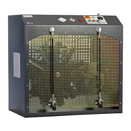
Page 9: Unit Assembly
D E S C R I P T I O N Unit Assembly Designation Filling pressure gauge Switchboard Filling hoses (optional: without filling hoses) Filling valves Page A - 7 LW SC-300 E / LW SC-350 E Version: 06.12.2022... -
Page 10: Switchboard
D E S C R I P T I O N Switchboard Designation Emergency shut-off switch Hour counter ON button OFF button Drain test button Page A - 8 LW SC-300 E / LW SC-350 E Version: 06.12.2022... -
Page 11: Flow Chart
19. Filtergehäuse / Filter Housing 38. Kreuzventil (Option) / Filling Valve „Cross 20. Öl-/Wasserabscheider / Oil-/Water Separator Design“ (Option) 21. Druckhalteventil / Pressure Maintaining Valve 39. Füllschlauch / Filling Hose Page A - 9 LW SC-300 E / LW SC-350 E Version: 06.12.2022... -
Page 12: Safety Precautions
S A F E T Y P R E C A U T I O N S... -
Page 13: Intended Use / Operators
Only trained personnel are permitted to work on the unit! Warning Work on the electrical equipment on / with the machine / unit may only be carried out by qualified electricians. Page A - 11 LW SC-300 E / LW SC-350 E Version: 06.12.2022... -
Page 14: Safety Instructions On The Unit
Importance of notes and warning signs that are affixed to the compressor according to the application or its equipment. Warning Note High voltage! Ensure correct direction of rotation! Page A - 12 LW SC-300 E / LW SC-350 E Version: 06.12.2022... -
Page 15: General Safety Precautions
• Do not use the product in areas prone to explosion or in the presence of flammable gases. The product is not designed for these applications. An explosion might be the result if certain conditions apply. Page A - 13 LW SC-300 E / LW SC-350 E Version: 06.12.2022... -
Page 16: Unit Customised Safety Notices
• Soundproofing equipment on the compressor has to be activated in safety function during operation. • When handling with fats, oils and other chemical agents, observe the note for the product- related safety. Page A - 14 LW SC-300 E / LW SC-350 E Version: 06.12.2022... -
Page 17: Maintenance Instructions
• Only personnel with particular knowledge and experience with pneumatics may carry out work on pneumatic equipment. • Only personnel with particular knowledge and experience in gas equipment may carry out work on gas equipment. Page A - 15 LW SC-300 E / LW SC-350 E Version: 06.12.2022... -
Page 18: Transportation Instructions / Safety Regulations
No guarantees whatsoever are valid for damage caused or favoured by the non-consideration of these directions for use. Page A - 16 LW SC-300 E / LW SC-350 E Version: 06.12.2022... -
Page 19: Installation
I N S T A L L A T I O N... -
Page 20: Installation In Closed Rooms
Pos. Length of Intake Hose [m] Diameter of Intake Hose [mm] ≤ 03 Ø 30 ≤ 10 Ø 80 ≤ 15 Ø 100 ≤ 20 Ø 120 Page A - 18 LW SC-300 E / LW SC-350 E Version: 06.12.2022... -
Page 21: Dimensions
I N S T A L L A T I O N Dimensions Fig. Dimensions Page A - 19 LW SC-300 E / LW SC-350 E Version: 06.12.2022... -
Page 22: Minimum Distances
Front side min. 1500 mm, sides min. 500 mm, rear side min. 500 mm. Avoid anything in this area which can restrict the cooling air flow. 1500 Fig. Minimum distances Page A - 20 LW SC-300 E / LW SC-350 E Version: 06.12.2022... -
Page 23: Ventilation
• The fan capacity for fresh air and warm air must meet at least the required cooling air flow. The fans must have the same capacity. Fig. Ventilation through facade Fig. Ventilation via ventilation stack Page A - 21 LW SC-300 E / LW SC-350 E Version: 06.12.2022... -
Page 24: Electrical Installation
• Fuse the motor correctly (see table; use slow-blow fuses). Fig. Compressor name plate Designation Circuit diagram number Compressor type Power supply Frequency Motor current consumption Nominal motor power Page A - 22 LW SC-300 E / LW SC-350 E Version: 06.12.2022... - Page 25 Recommended fuses for 220 - 240 V operating voltage Nominal motor power Fusing start A Connection in mm² [kw] Direct Star/Delta Contactor supply Motor S/D 14.8 19.6 26.4 18.5 Page A - 23 LW SC-300 E / LW SC-350 E Version: 06.12.2022...
-
Page 26: Operation
O P E R A T I O N... -
Page 27: Important Operation Instructions
Ensure that all persons handling the compressor are familiar with function and operation of the unit. Wear hearing protection When working on a running machine, always wear hearing protection. Page A - 25 LW SC-300 E / LW SC-350 E Version: 06.12.2022... -
Page 28: First Commissioning
- Drain test - press the test button - If correct, air escapes Stop the compressor by pushing the OFF button. 10. Open all filling valves carefully to vent. Page A - 26 LW SC-300 E / LW SC-350 E Version: 06.12.2022... - Page 29 Settings Motor Type Initial Installation Operation after running in Electric motors 50Hz 500 N 400 N Electric motors 60Hz 400 N 300 N Page A - 27 LW SC-300 E / LW SC-350 E Version: 06.12.2022...
- Page 30 2nd and 3rd stages can not be sufficiently lubricated, with the consequence that the pistons will be damaged. Furthermore, cooling air flow will not be sufficient. Rotation direction arrow Page A - 28 LW SC-300 E / LW SC-350 E Version: 06.12.2022...
-
Page 31: Daily Commissioning
• Check compressor oil level by the oil sight glass. • Check if filter cartridge is in place / observe filter cartridge life! • Ensure toxic-free, pure intake air. Page A - 29 LW SC-300 E / LW SC-350 E Version: 06.12.2022... -
Page 32: Filling Procedure
Fill compressed air cylinders to the desired pressure, subsequently close the filling valves slowly. Close and vent all filling valves. Disconnect all compressed air cylinders from filling valves. Page A - 30 LW SC-300 E / LW SC-350 E Version: 06.12.2022... -
Page 33: Switch Off The Compressor
(only in case of emergency!). Note After automatic or manual switching off, all pressure vessels and filter housings of the compressor will be automatically vented. Page A - 31 LW SC-300 E / LW SC-350 E Version: 06.12.2022... -
Page 34: Remedying Faults
R E M E D Y I N G F A U L T S... - Page 35 Cylinder(s), piston(s) or piston ring(s) used up Replace V-belt slips Tension V-belt See chapter "Final pressure can not be reached" See chapter "Final pressure can not be reached" Page A - 33 LW SC-300 E / LW SC-350 E Version: 06.12.2022...
- Page 36 Mole carbon filter cartridge saturated Replace Compressor oil unsuitable Use prescribed oil quality Filter cartridge unsuitable Use prescribed filter type Cylinder(s), piston(s) or piston ring(s) defective Replace Page A - 34 LW SC-300 E / LW SC-350 E Version: 06.12.2022...
- Page 37 Check fusing of the power supply / observe Valid only for E models regulations Emergency stop switch has tripped Unlock emergency stop switch, close compressor housing door correctly Page A - 35 LW SC-300 E / LW SC-350 E Version: 06.12.2022...
- Page 38 Operating temperature too high Observe prescribed operating temperatures Oil leak at the compressor block Tighten corresponding mounting screws, if necessary replace corresponding paper sealing / o-ring / shaft seal Page A - 36 LW SC-300 E / LW SC-350 E Version: 06.12.2022...
-
Page 39: Maintenance And Service
M A I N T E N A N C E A N D S E R V I C E... -
Page 40: Service, Repair And Maintenance
Carry out maintenance or service work when the unit is switched off and protected against unexpected restart. Warning Risk of burns! Carry out maintenance or service work when the unit has cooled down. Page A - 38 LW SC-300 E / LW SC-350 E Version: 06.12.2022... -
Page 41: Maintenance Lists / Maintenance Intervals
Oil change 000001 Every 3 months or as required Maintenance work Type Quantity Order No. Check automatic condensate drain, open manual condensate taps Check/Retorque all connections and bolts Page A - 39 LW SC-300 E / LW SC-350 E Version: 06.12.2022... - Page 42 Every 500 operating hours Maintenance work Type Quantity Order No. Change intake filter 000170 Check pressure maintaining/non-return valve Check V-belt tension and condition see above see above see above Page A - 40 LW SC-300 E / LW SC-350 E Version: 06.12.2022...
- Page 43 Replace o-rings of the final filter housing 001769 Replace sintered metal filter of oil filter 000184 Replace o-ring of oil filter 000435 Oil change ( at least once a year!) 000001 Page A - 41 LW SC-300 E / LW SC-350 E Version: 06.12.2022...
- Page 44 Order No. Replace all inlet and outlet valves incl. Gaskets 1st stage 002093 2nd stage 000542 3rd stage 000543 Upper gasket 1st 000257 Lower gasket 1st 000258 Page A - 42 LW SC-300 E / LW SC-350 E Version: 06.12.2022...
-
Page 45: Check V-Belt Tension / Tension V-Belt
Settings Motor Type Initial Installation Operation after running in Electric motors 50Hz 500 N 400 N Electric motors 60Hz 400 N 300 N Page A - 43 LW SC-300 E / LW SC-350 E Version: 06.12.2022... -
Page 46: Compressor Lubrication / Check Oil Level
The oil level should be between the notch and the end of the Oil dipstick oil dipstick. If there is no oil between the notch and the end of the oil dipstick, refill immediately new full synthetic compressor oil. Page A - 44 LW SC-300 E / LW SC-350 E Version: 06.12.2022... -
Page 47: Oil Change
Oil and oil capacity Approx. 1800 ml synthetic compressor oil is necessary for one oil change. Only use synthetic compressor oil which is recommended as suitable from L&W. Page A - 45 LW SC-300 E / LW SC-350 E Version: 06.12.2022... -
Page 48: Oil Filter Maintenance
Fig. 2 - Loosen mounting screws of the filter cover Fig. 3 - Change o-ring Fig. 4 - Change sinter filter Fig. 5 - Place filter washer and washer Page A - 46 LW SC-300 E / LW SC-350 E Version: 06.12.2022... -
Page 49: Final Pressure Switch
Example settings: Safety valve Max. Operating Pressure 225 bar 215 bar 250 bar 240 bar 330 bar 320 bar Page A - 47 LW SC-300 E / LW SC-350 E Version: 06.12.2022... -
Page 50: Maintenance And Service
All oil / water separators have an integrated sinter filter which has to be replaced every 1,000 operating hours. Oil / water separators final stage Page A - 48 LW SC-300 E / LW SC-350 E Version: 06.12.2022... -
Page 51: Oil / Water Separators 2Nd Stage - Maintenance
The oil / water separator maintenance is now completed. Fig. 2 - Remove sinter filter holder Fig. 3 - Change sinter filter Fig. 4 - Change o-ring Page A - 49 LW SC-300 E / LW SC-350 E Version: 06.12.2022... -
Page 52: Oil / Water Separators Final Stage - Maintenance
• Tighten pipe connections and mounting screws. The oil / water separator maintenance is now completed. Fig. 1 - Loosen ring nut Fig. 2 - Change sinter filter Fig. 3 - Change o-ring Page A - 50 LW SC-300 E / LW SC-350 E Version: 06.12.2022... -
Page 53: Pneumatic Condensate Valve - Maintenance
• Tighten pipe connections and mounting screws. Pneumatic Condensate Valve Pneumatic condensate valve maintenance is now completed. Fig. 2 - Loosen connection Fig. 3 - Change sinter filter Page A - 51 LW SC-300 E / LW SC-350 E Version: 06.12.2022... -
Page 54: Filter Housing / Filter Cartridge
Filter cartridges should be changed at the following intervals, at +20°C or more often, depending on humidity and ambient temperature: Standard life time at 20°C: • 28 hours for LW SC-300 E • 43 hours for LW SC-350 E Page A - 52 LW SC-300 E / LW SC-350 E Version: 06.12.2022... -
Page 55: Filter Cartridge Change
Do not run the compressor with empty unfilled cartridges. Only use genuine L&W cartridges. Filter cartridge change LW SC-300 E / LW SC-350 E Change filter cartridge as follows: · Stop the compressor and carefully open the drain valves. Wait till the filter housing is completely vented;... -
Page 56: Filter Housing - Maintenance
• Mount the filter housing • Mount the mounting bracket (Fig. 3) The filter housing maintenance is now completed. Fig. 2 - Change o-ring Abb. 3 - Befestigungsbügel Page A - 54 LW SC-300 E / LW SC-350 E Version: 06.12.2022... -
Page 57: Inlet Filters / Inlet Filter Cartridge Change
• Assemble intake filter • Tighten nut The inlet filter cartridge change is now completed. (Fig.2) Remove cover and (Fig.1) Loose nut (Fig.3) Mount the intake filter replace filter cartridge Page A - 55 LW SC-300 E / LW SC-350 E Version: 06.12.2022... -
Page 58: Cylinder Heads And Valves
There are no special tools required to replace these valves. Available special tools Special tools are not necessary for dismounting inlet and outlet valves but make work easier. Order number: 006847 Special tool Page A - 56 LW SC-300 E / LW SC-350 E Version: 06.12.2022... -
Page 59: Replace Inlet And Outlet Valve 1St Stage
• Check valve head if defective Install Inlet / Outlet Valve - see following page Fig. 2 - Pull out inlet and outlet valve Fig. 3 - Copper valve ring Page A - 57 LW SC-300 E / LW SC-350 E Version: 06.12.2022... - Page 60 • Connect pipe connections and tighten (Fig. 6). Inlet and outlet valves change 1st stage is now completed. Fig. 5 - Screw valve head screws in Fig. 6 - Connect pipe connections and tighten Page A - 58 LW SC-300 E / LW SC-350 E Version: 06.12.2022...
-
Page 61: Replace Inlet And Outlet Valves 2Nd And 3Rd Stage
Fig. 3 - Remove lower valve gasket Fig. 4 - Remove inlet and outlet valve Fig. 5 - Ensure correct mounting position of the upper valve gasket Page A - 59 LW SC-300 E / LW SC-350 E Version: 06.12.2022... -
Page 62: Safety Valves
If a safety valve blows off, it indicates problems with either inlet or outlet valve of the following stage. Note Replace defective safety valves immediately! Safety valve 3rd stage Page A - 60 LW SC-300 E / LW SC-350 E Version: 06.12.2022... -
Page 63: Pressure Maintaining / Non Return Valve
/ condensate drain valves. After compressor stop, the indicated filling pressure remains constant, if the non return valve is working correctly. Page A - 61 LW SC-300 E / LW SC-350 E Version: 06.12.2022... -
Page 64: Safety Valve Test
• Turn the adjusting screw of the final pressure switch back (one turn counterclockwise). Pressure switch • Check the cut-out pressure. Adjust if necessary! The safety valve test is now completed. Page A - 62 LW SC-300 E / LW SC-350 E Version: 06.12.2022... -
Page 65: Leak Test
(Leichtes Zischen durch Ansaugfilterstutzen ist zu vernachlässigen). Sollten Abblasgeräusche auftreten, lokalisieren Sie die Abblasstelle(n). • Lassen Sie den AUS-Schalter los. Der Leckage-Test ist nun abgeschlossen. Abb. - AUS-Schalter Page A - 63 LW SC-300 E / LW SC-350 E Version: 06.12.2022... -
Page 66: Pressure Gas Vessel Test
Max. numbers of load cycles for operation with max. allowable pressure variation Final pressure [bar] Load cycles Operating hours [h] 35.000 8.750 Caution The filter container (P/N: 010706) has to be replaced after 15 years! Page A - 64 LW SC-300 E / LW SC-350 E Version: 06.12.2022... -
Page 67: Maintenance Records
M A I N T E N A N C E R E C O R D S... - Page 68 By adding themselves to this list, the person that signs it confirms having been given a yearly introduction/instruction about the function and operation of the compressor unit.Furthermore, they have be informed about the relevant safety rules and regualtions (TRG, DGRL, BetrSichV, GSG, GSGV). Page A - 66 LW SC-300 E / LW SC-350 E Version: 06.12.2022...
- Page 69 M A I N T E N A N C E R E C O R D S Top up oil, oil change Date Operating hours Oil quantity [l] Name Page A - 67 LW SC-300 E / LW SC-350 E Version: 06.12.2022...
- Page 70 M A I N T E N A N C E R E C O R D S Cartridge change Date Operating hours Difference Name Page A - 68 LW SC-300 E / LW SC-350 E Version: 06.12.2022...
- Page 71 M A I N T E N A N C E R E C O R D S Maintenance work Description Date, signature Page A - 69 LW SC-300 E / LW SC-350 E Version: 06.12.2022...
- Page 72 M A I N T E N A N C E R E C O R D S Replaced Parts Designation Part number Date, signature Page A - 70 LW SC-300 E / LW SC-350 E Version: 06.12.2022...
-
Page 73: Conservation / Storage Of The Compressor
Check safety valve relief pressure of final stage and/or pressure switch setting. • Check all connections and pipe work for leaks. Once all above steps are completed, compressor unit is now ready for use. Page A - 71 LW SC-300 E / LW SC-350 E Version: 06.12.2022... -
Page 74: Transportation Instructions / Disposal
The device can be returned to L&W. Please do not hesitate to contact us if you have any further questions on this issue. Page A - 72 LW SC-300 E / LW SC-350 E Version: 06.12.2022... - Page 75 A T T A C H M E N T Version: 11/12-E...
- Page 76 OPERATING INSTRUCTION FOR SAFETY VALVE Lenhardt & Wagner GmbH An der Tuchbleiche 39 D-68623 Lampertheim – Hüttenfeld www.lw-compressors.com Operating Instruction Safety valve Typ: SiV2 BKZ TÜV.SV.19-1140.5.G.V.P CE 0091 AlMgSi1 F31 1100* Lenhardt & Wagner Set pressure: see mark (hand wheel on top of valve) Maximum outflow: Set pressure 100-159 bar: 750 l / min...
- Page 77 OPERATING INSTRUCTION FOR SAFETY VALVE In order to prevent manipulation of the set pressure, all safety valves are factory fitted with a seal. A safety valve on which the seal has been removed, must be returned to the manufacturer for repair / adjustment before further use.
- Page 78 OPERATING INSTRUCTION FOR SAFETY VALVE Manufacturer: Lenhardt & Wagner GmbH An der Tuchbleiche 39 D-68623 Lampertheim – Hüttenfeld Contact: E-Mail: service@lw-compressors.com Web: www.lw-compressors.com Tel.: +49 (0) 6256 – 85880 0 Fax: +49 (0) 6256 – 85880 14 Note: Only use safety valves which are in a technically perfect condition, for its intended purpose, safety and danger awareness, in compliance with the operating instructions! Faults which could affect safety must be rectified immediately! Notes:...
- Page 79 INFORMATION ON THE SERVICE LIFE OF L&W HIGH PRESSURE HOSES...
- Page 80 CONTENTS Testing hose lines Testing hose lines ............................3 Testing after assembly and before commissioning ................3 Recurring test ............................... 4 Procedure for hose lines found to be "defective" ................. 4 Test intervals ..............................4 Persons qualified to test hose lines ......................5 Maintenance Replacing hose lines ...........................
-
Page 81: Testing Hose Lines
TESTING HOSE LINES Testing hose lines An essential factor in ensuring operational safety when handling L&W compressors is the proper testing of the hose lines used. Tests are necessary: After assembly and before commissioning the hose line. After accidents, changes (modifications) to the compressor system, longer periods of non- ... -
Page 82: Recurring Test
TESTING HOSE LINES Recurring test Since hose lines are subject to influences that cause damage during operation and can lead to dangerous situations, they must be tested recurrently at fixed intervals. The aim of recurring tests is to detect and repair damage in good time. The objective is to ensure that the system remains in a safe condition. -
Page 83: Persons Qualified To Test Hose Lines
TESTING HOSE LINES Persons qualified to test hose lines A qualified person is a person who, through his or her professional training, professional experience and recent professional activity, has the necessary specialist knowledge required for testing work equipment - in this case for testing hose lines. These requirements are defined in the Technical Rules for Industrial Safety TRBS 1203 "Qualified persons - general requirements"... -
Page 84: Replacing Hose Lines
MAINTENAN Replacing hose lines As a general rule, even when stored properly and subjected to permissible stress during use, all hose lines are subject to natural aging, which changes the material and composite properties and reduces the performance of the hose lines. This limits the service life of a hose line and the operator must ensure that hose lines are replaced at appropriate intervals. -
Page 85: Service Life
SERVICE LIFE Service life of L&W high pressure hoses When determining the service life or the replacement interval of the individual hose lines, the concrete specifications and recommendations of the hose line or machine manufacturer must be observed. Furthermore, empirical values resulting from previous tests done under the prevailing operating conditions on site are also relevant. -
Page 86: Storage
STORAGE Storing hose lines When storing hose lines, storage conditions must be aimed at minimizing the natural aging that occurs over time and the associated change in material and composite properties. For this purpose, the following information must be provided: ... - Page 87 ANNEX...
- Page 88 ANNEX SCOPE OF TESTING; TEST CRITERIA Recommended scope of testing "visual inspection" (before initial commissioning or recommissioning) Is all user information required for safe operation of the system available (e.g. flow chart, operating instructions)? Do the hose lines comply with the flow chart or parts list? ...
- Page 89 ANNEX SCOPE OF TESTING; TEST CRITERIA Recommended scope of testing "Functional test" (before initial or recommissioning) Note: Visual inspection must be carried out before the functional test All parts of the system must be tested at least at the maximum working pressure that could be achieved taking into account all intended applications:...
Need help?
Do you have a question about the SC-300 E and is the answer not in the manual?
Questions and answers