Advertisement
Advertisement
Table of Contents

Subscribe to Our Youtube Channel
Related Manuals for Viking DBCV3638


Summary of Contents for Viking DBCV3638
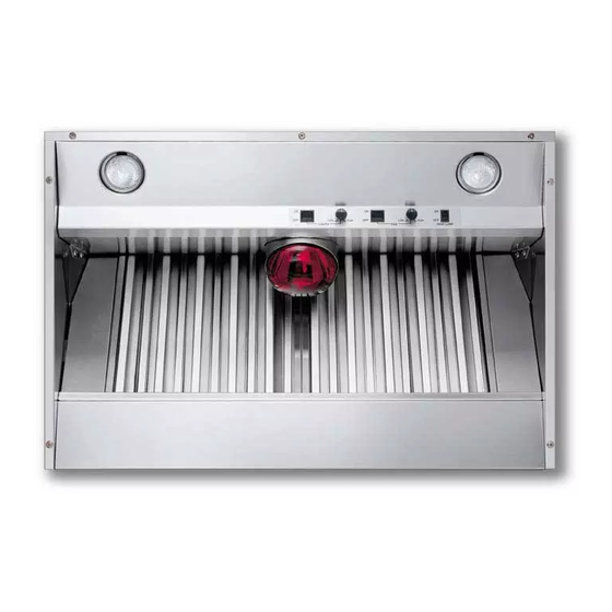
- Page 1 Viking Installation Guide Designer Series Built-In Custom Ventilator System...
- Page 2 These units will not function with a single speed ventilator. All Viking Range ventilator kits are designed specifically for use with Viking Range hoods. Use of any non-Viking Range ventilator kit will void the hood warranty. WARNING - TO REDUCE THE RISK OF FIRE, ELECTRIC...
-
Page 3: Basic Specifications
BASIC SPECIFICATIONS INTERIOR AND EXTERIOR POWER BUILT-IN WALL CUSTOM VENTILATOR SYSTEMS RECOM. DESCRIPTION 30”W. 300 int./440 int. 900 ext./ 1200 ext. 36”W. 300 int./440 int. 900 ext./ 1200 ext. 42”W. 440 int./ 900 ext./ 1200 ext. 48”W. 880 int./ 1200 ext. 1500 ext. -
Page 4: Electrical Supply
HEIGHT OF HOOD The bottom of the hood should be 30” (76.2 cm) to 36” (91.4 cm) above the countertop. This would typically result in the bottom of the hood being 66” (167.6 cm) to 72” (182.9 cm) above the floor. For best performance, it is recommended that the bottom of the hood be 30”... -
Page 5: Installing Hood Canopy
INSTALLING HOOD CANOPY (DBCV/DICV Custom Ventilator Kits Only) *For best results, center the unit over the burners of the cooking product (front to back; right to left). Make sure the back wall of the custom hood canopy is flush with the cutout so the ventilator system may be mounted as shown below. - Page 6 VENTILATOR KIT INSTALLATION DIV300/DiV440 (Also see instructions supplied with ventilator kit) 1. Attach DAMPER to VENTILATOR, as shown, using three (3) HEX SCREWS (provided). Note: Damper flange to be captured by screw heads. 2. Lift ventilator into position inside the hood. 3.
- Page 7 DiV880 (Also see instructions supplied with ventilator kit) 1. Remove front and rear filter rails from hood. 2. Lift ventilator into position inside the hood. 3. Engage (2) tabs on ventilator into (2) slots in top of hood. 4. Fasten ventilator to two (2) THREADED STUDS, using two (2) HEX NUTS (provided). 5.
- Page 8 CONNECTING DUCTWORK -EXTERNAL POWER DEV900/DEV1200/dev1500 (Also see instructions supplied with ventilator kit) 1. Run 10” (25.4 cm) round steel ductwork from external blower to the installation location. For best performance, use the straightest possible duct run and the fewest number of elbows. Tape all joints. 2.
- Page 9 ROOF INSTALLATION EXTERIOR-POWER VENTILATOR DEV900-Exterior Power Ventilator Kit (900CFM) (also see instructions supplied with ventilator kit) 1. Locate the blower on the rear slope of the roof. Place it in a location to minimize duct run. The location should be free of obstacles (T.V. leads, electrical lines, etc.). Bear in mind, if the blower top is level with the roof peak, it will not be seen from the street.
-
Page 10: Wall Installation
WALL INSTALLATION EXTERIOR-POWER VENTILATOR DEV900-Exterior-Power Ventilator Kit (900CFM) 1. Choose a position on the outside wall. Min. 24” (61.0 cm from ground may vary depending on local codes or location. Make sure that no wall studs, pipes or wires run through the opening area. 2. - Page 11 ROOF INSTALLATION EXTERIOR-POWER VENTILATOR Exterior Power Ventilator (also see instructions supplied with ventilator kit) 1. Locate the blower on the rear slope of the roof. Place it in a location to minimize duct run. The location should be free of obstacles (T.V. leads, electrical lines, etc.). Bear in mind, if the blower top is level with the roof peak, it will not be seen from the street.
-
Page 12: Filter Installation
WALL INSTALLATION EXTERIOR-POWER VENTILATOR Exterior Power Ventilator Kit 1. Choose a position on the outside wall. Min. 24” (61.0 cm from ground may vary depending on local codes or location. Make sure that no wall studs, pipes or wires run through the opening area. -
Page 13: Exterior Ventilator Dimensions
EXTERIOR VENTILATOR DIMENSIONS DEV900 10” Dia. 1 /4 ” (71.8 cm) 1 /2 ” (39.4 cm) 14” (35.6 cm) 3 1/2” (8.9 cm) 3 /4 ” (62.9 cm) 3 /4 ” (52.7 cm) (74.9 cm) 1 /2 ” (62.2 cm) Opening for wiring 3 /4... - Page 14 30” W./36” W./42” W. BUILT-IN WALL CUSTOM VENTILATOR SYSTEM DIMENSIONS 5” (12.7 cm) For 900 or 1200 CFM External Ventilation Installation 16” (40.6 cm) (15.2 cm) 6 1/8” (15.6 cm) 17 1/4” (43.8 cm) 8” Round for External Ventilation Duct* For 900 or 1200 CFM External Ventilation Installation (10”...
- Page 15 48” W. BUILT-IN WALL CUSTOM VENTILATOR SYSTEM DIMENSIONS 6 1/8” (15.6 cm) 17 1/4” (43.8 cm) 11” (27.9 cm) 10” (25.4 cm) 5” (12.7 cm) For 880 CFM Internal and 1200 or 1500 CFM External Ventilation Installation 47 5/8” (121.0 cm) 46 5/8”...
- Page 16 36” W./42” W. BUILT-IN ISLAND CUSTOM VENTILATOR SYSTEM DIMENSIONS 11” (27.9 cm) 8” (20.3cm) 5” (12.7 cm) For 900, 1200, or 1500 CFM External** Ventilation Installation 16” (40.6 cm) 11 1/8” (28.3 cm) 21” (53.3 cm) 22 1/4” (56.5 cm) 8”...
- Page 17 54” W. BUILT-IN ISLAND CUSTOM VENTILATOR SYSTEM DIMENSIONS 21” (53.3 cm) 22 1/4” (56.5 cm) 11” (27.9 cm) 10” (25.4 cm) 5” (12.7 cm) For 880 CFM Internal and 1200 or 1500 External Ventilation Installation 53 5/8” (136.2 cm) 52 5/8” (133.7 cm) 26 13/16”...
- Page 18 WIRING DIAGRAM BUILT-IN DESIGNER HOODS REFER ONLY TO FEATURES EQUIPPED WITH THIS UNIT.
- Page 19 Viking Range Corporation 111 Front Street Greenwood, Mississippi 38930 USA (662) 455-1200 For more product information, call 1-888-VIKING1 (845-4641) or visit the Viking Web site at vikingrange.com F20198I (PS042707J)
Need help?
Do you have a question about the DBCV3638 and is the answer not in the manual?
Questions and answers