Advertisement
Quick Links
Advertisement

Related Manuals for Chauvin Arnoux C.A. 760N


Summary of Contents for Chauvin Arnoux C.A. 760N
- Page 1 VOLTAGE DETECTOR „ C.A 760N User's manual E N G L I S H...
- Page 2 Thank you for purchasing a C.A 760N voltage detector. For best results from your instrument: „ read these operating instructions carefully, „ comply with the precautions for use. WARNING, risk of DANGER! The operator must refer to these instructions whenever this danger symbol appears.
-
Page 3: Table Of Contents
PRECAUTIONS FOR USE This device is protected against voltages up to 600V with respect to earth in measurement category IV. The protection provided by the device may be compromised if it is used other than as specified by the manufacturer and so endanger the user. -
Page 4: Presentation
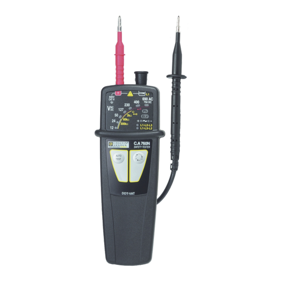
1. PRESENTATION 1.1. C.A 760N Black lead terminated Red test probe. by a test probe. Connection terminals. Bargraph. Phase indica- 600V tor. 690 AC CAT IV 750 DC Hazardous Ω Ω voltage indi- Ω 300k Ω L1-L2-L3 cator. L1-L3-L2 Polarity indi- C.A 760N SAFETY TESTER cator. - Page 5 1.2. ON THE BACk When the device is not in use, the test probes can be stowed on the back. Removable protec- tive caps. Red test probe. Guards. Black test probe. Battery compart- ment cover.
- Page 6 1.3. FUNCTIONS The C.A 760N is a Voltage Detector with indicator lights. It complies with the requirements of standard IEC 61243-3. The main function of the C.A 760N is to test for the absence of any voltage. It detects hazardous voltages, meaning voltages exceeding the ELV (extra low voltage: 50 V or 120 V even if its batteries are low or missing.
-
Page 7: Use
2. USE This device is a detector. The indications it provides must not be used for measurement purposes. 2.1. SELF-TEST Before using the C.A 760N, perform a self-test. This checks the integrity of the leads, the proper operation of the elec- tronic circuit, and the battery voltage. - Page 8 „ If every third indicator is off, there is a problem with the leads. Check that they are correctly connected and that they are actually touching, then press the AUTO TEST button again. If the problem persists, the lead and/or the test probe must be replaced.
- Page 9 If the voltage present is: „ AC, the indicators light to indicate its value and the + (green) and - (orange) indicators light. 600V 690 AC CAT IV 750 DC Ω Ω Ω 300k Ω „ DC, the indicators light to indicate its value and the + in- dicator (green) or the - indicator (orange) lights to indicate the polarity.
- Page 10 2.3. CONTINUITy LEVEL INDICATION Connect the red test probe to the + terminal and the black lead to the COM terminal. Keep your hands behind the guards of the device and of the test probe. Place the test probes on the element to be tested and main- tain a firm contact.
- Page 11 If the test probe is in fact on the phase, the Ph (phase) indica- tor flashes and the device beeps. 600V 690 AC CAT IV 750 DC Ω Ω Ω 300k Ω Warning: if the Ph indicator is not flashing, that does not mean that there is no hazardous voltage on the outlet.
- Page 12 If there is a problem, in other words, if the device fails to detect a change of phase within 10 seconds or if the phases are not balanced, it reports an error by emitting two low- pitched beeps. Otherwise, the device indicates the phase order by lighting: „...
-
Page 13: Characteristics
3. CHARACTERISTICS 3.1. REFERENCE CONDITIONS quantity of influence Reference values Temperature 23±5°C Relative humidity 30 to 75 % HR Supply voltage 3±0,1V Frequency of the measured signal DC or 45 to 65 Hz Type of signal sinusoidal External electric field <1V/m DC external magnetic field <40A/m... - Page 14 3.2.3. PHASE IDENTIFICATION 15Hz<frequency<65Hz and 45Hz<frequency ≤65Hz 50 V <voltage<690 V 150 V <voltage<690 V and frequency<45Hz 3.2.4. PHASE-ORDER Frequency between 45 and 400Hz. Voltage between 50 and 690 Vac between phases. Time to acquisition of the information after contact ≤1s. Retention time of the information: 10s.
- Page 15 The batteries can be replaced by rechargeable batteries, but the life between charges will be much shorter. 3.5. CHARACTERISTICS OF CONSTRUCTION Dimensions (LxWxH) 163 x 64 x 40mm Weight approximately 210g Cord length 90cm Protection class IP65 per IEC 60529 IK04 per IEC 50102 Drop 2 metres...
-
Page 16: Maintenance
This instrument should be checked at least once a year. For checking and calibration, contact one of our accredited metrology laboratories (information and contact details available on request), at our Chauvin Arnoux subsidiary or the branch in your country. 4.4. REPAIR For all repairs before or after expiry of warranty, please return the device to your distributor. -
Page 17: Warranty
5. WARRANTy Except as otherwise stated, our warranty is valid for twelve months starting from the date on which the equipment was sold. Extract from our General Conditions of Sale provided on request. The warranty does not apply in the following cases: „...
Need help?
Do you have a question about the C.A. 760N and is the answer not in the manual?
Questions and answers