Table of Contents
Advertisement
Quick Links
Installation and Operation of the
AMC-1225 Sensor Modules For Use With AMC
IMPORTANT:
Please read these installation and operating instructions completely
and carefully before starting.
filename: 3573405B, DOC, AMC1225 Manual.doc
215 Colonnade Road South, Ottawa, Ontario, Canada K2E 7K3
Tel: (613) 225-9531 • Fax: (613) 225-6965 • U.S. & CANADA Toll Free: (800) 465-5777
E-mail: gas@armstrongmonitoring.com • Internet: www.armstrongmonitoring.com/gas/
1225
Sensor Modules
INSTRUCTIONS
Gas Monitors
The Armstrong Monitoring Corporation
Copyright ©, August 2018, AMC
Advertisement
Table of Contents

Subscribe to Our Youtube Channel
Related Manuals for AMC AMC-1225


Summary of Contents for AMC AMC-1225
- Page 1 1225 Sensor Modules INSTRUCTIONS Installation and Operation of the AMC-1225 Sensor Modules For Use With AMC Gas Monitors IMPORTANT: Please read these installation and operating instructions completely and carefully before starting. Copyright ©, August 2018, AMC filename: 3573405B, DOC, AMC1225 Manual.doc...
-
Page 2: Table Of Contents
6.3 SENSOR REPLACEMENT ..................16 Figure 2-1 AMC-1224, 1225 Sensor Modules ................3 Figure 3-1 Internal Features of the AMC-1224, 1225 Sensor Module .......... 6 Figure 4-1 Hole Mounting ......................8 Figure 4-2 Pole Mounting ......................9 Figure 4-3 Detail Wiring of Sensor Modules ................11 Figure 4-4 Typical System Configuration Layouts .............. -
Page 3: Warranty
AMC shall have no liability for labour or freight costs, or any other costs or charges in excess of the amount of the invoice for the products. -
Page 4: Product Information
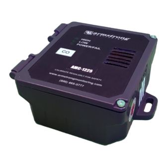
AMC-1225 SENSOR MODULES 2 PRODUCT INFORMATION Figure 2-1 AMC-1225 Sensor Modules 2.1 AMC-1225 SENSOR MODULES Sensor Module Part Number …………………………… Sensor Module Serial Number …………………………. Sensor Element Part Number………………….……….. Sensor Element Serial Number ………………………... Wire Gauge ………………………………………………. 18 AWG @ 150 ft max between units Power Supply Requirement …………………………….. -
Page 5: Factory Calibration
AMC-1225 SENSOR MODULES 2.2 FACTORY CALIBRATION Gas type …………………………………………………………… Low Alarm Setting ………………………………………………... High Alarm Setting ……………………………………………….. Calibration Mixing Chamber Part Number……………………… Note: All Armstrong Monitoring systems must be installed and maintained according to instructions, to ensure proper operation. Only qualified technicians should install and maintain the equipment. -
Page 6: Product Description
AMC-1225 SENSOR MODULES 3 PRODUCT DESCRIPTION In this section a general product description is given followed by a detailed list of the AMC-1224, 1225 unit’s internal features. 3.1 GENERAL DESCRIPTION The AMC-1225 sensor unit provides continuous, reliable surveillance of surrounding air for traces of hazardous gases that are listed in the Product Information Section. - Page 7 AMC-1225 SENSOR MODULES Figure 3-1 Internal Features of the AMC-1225 Sensor Module...
-
Page 8: Installation
AMC-1225 SENSOR MODULES 4 INSTALLATION This section discusses topics relating to the proper installation of the AMC-1225 unit. The proper location, sensor wiring selection and multi-unit interconnection are all discussed in detail in the following section. 4.1 LOCATION AND MOUNTING Mount the sensor unit on a solid non-vibrating surface or structure easily accessible for status checking and calibration. - Page 9 AMC-1225 SENSOR MODULES Figure 4-1 Standard Enclosure Mounting...
-
Page 10: Cable Selection And Wiring
AMC-1225 SENSOR MODULES Figure 4-2 Pole Mounting 4.2 CABLE SELECTION AND WIRING To gain access to the terminal blocks, remove the four (4) screws and front panel from the housing. This will expose the field wiring terminals. The sensor / transmitter output (-,s,+) terminal block connects to the input terminal block of the previous unit or to the sensor / transmitter terminal block in the monitor as shown in Figure 4-3. -
Page 11: Multi-Unit Interconnection
AMC-1225 SENSOR MODULES NOTE: Turn off the power supply before removing or replacing the sensor. Connection should be made using 3 conductor shielded cable ( shield must be grounded at the monitor ). Run cable through steel conduit for best signal transmission and maximum noise rejection. - Page 12 AMC-1225 SENSOR MODULES Figure 4-3 Detail Wiring of Sensor Modules...
-
Page 13: Operation And Calibration
Figure 4-4 Typical System Configuration Layouts 5 OPERATION AND CALIBRATION This section covers instructions for the proper operation and calibration of the AMC-1224, 1225 unit. The operation principles are described in further detail followed by different types of periodic adjustments that might be required throughout the lifetime of the equipment. -
Page 14: Operation
OFF the green LED viewed through the front panel. The condition will exist until the fault is corrected. 5.2 CALIBRATION The AMC-1225 sensor unit is factory calibrated at levels based on set standards. Calibration is recommended two times per year. Transmitters need to be returned to factory for calibration. - Page 15 AMC-1225 SENSOR MODULES NOTE: If the sensor has been replaced, adjust the SIGNAL first, then proceed with LOW alarm and HIGH alarm adjustments. Signal calibration is performed using a digital multimeter set to measure DC voltages to two (2) decimal places (e.g. 0.00 Volts).
- Page 16 AMC-1225 SENSOR MODULES Figure 5-1 Calibration/Verification set-up procedure...
-
Page 17: Maintenance
AMC-1225 SENSOR MODULES 6 MAINTENANCE This section covers topics related to the maintenance of the AMC-1225 unit. A general description of maintenance to be carried out is followed by a verification of operation and then details about the sensor replacement.
Need help?
Do you have a question about the AMC-1225 and is the answer not in the manual?
Questions and answers