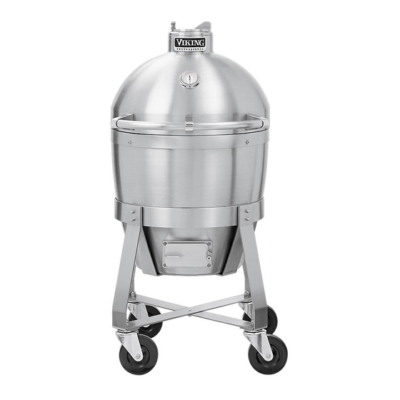
Viking Professional VCQS001SS Installation Instructions Manual
Outdoor cooker cart assembly
Hide thumbs
Also See for Professional VCQS001SS:
- Specifications (4 pages) ,
- Installation manual (6 pages) ,
- User manual (35 pages)
Advertisement
Quick Links
INSTALLATION
INSTRUCTIONS
C4
TM
OUTDOOR COOKER CART ASSEMBLY
Retain for Future Reference
IMPORTANT: PLEASE READ AND FOLLOW
1. Before beginning, please read these instructions completely and carefully.
2. Do not remove permanently affixed labels, warnings, or plates from product.
To mount the cooker to the cart:
Always wear gloves when installing the cooker. Although the cooker and cart is deburred prior to shipment, some
edges may still be sharp enough to cause injury during handling.
1. Remove the stainless steel side burner cover, side burner grates, burner bowls and grate support. (41" W. models
only)
2. Remove the top from the cart. (See Figure 1)
CAUTION: Keep hands and fingers away fro spring area.
3. Install two (2) shipping screws, (one set on each side). (See Figure 2) Remove teh two (2) top nuts and washers on
each side of the hinge mount.
4. Remove all inside parts.
Figure 2
Keep hands and fingers out of
spring area. Lift from bottom
or inside front of hinge.
Stainless cover
Grates
Burner bowls
Grate support
Figure 1
CAUTION
VIKING RANGE CORPORATION
Greenwood, Mississippi 38930 USA
Remove the (2) top nuts and
washers on each side of hinge
Install (2) shipping screws
(one on each side)
111 Front Street
(662) 455-1200
Cart top
Advertisement

Subscribe to Our Youtube Channel
Summary of Contents for Viking Professional VCQS001SS
- Page 1 Lift from bottom or inside front of hinge. Figure 1 CAUTION Install (2) shipping screws (one on each side) VIKING RANGE CORPORATION 111 Front Street Greenwood, Mississippi 38930 USA (662) 455-1200 Cart top Remove the (2) top nuts and...
- Page 2 5. With a minimum of two people, place the cooker on the cooker shelf located in the cart. Also, make sure the cooker is placed on the mounting bracket located on the cart directly under the hinge. The hinge and the inside damper vent should be used for hand holds.
- Page 3 The cart door comes adjusted from the factory. Depending on how level the surface the cart is being placed on, the door may need to be adjusted after the grill is assembled on the cart. There are two adjustment screws on the hinge receiver. (See Figure 5) 1) The front screw is used to center the door in the opening.
-
Page 4: For Your Safety
3. When the side burners are not in use, the gas supply must be turned off at the LP gas supply cylinder. 4. The pressure regulator and hose assembly supplied with the outdoor grill must be used. Replacement pressure regulators and hose assemblies must be those specified by the manufacturer. - Page 5 Check with your local gas utility company or with local codes for instructions on installing gas supply lines. Be sure to check on type and size of run and how deep to bury the lines. If the gas line is too small, the grill will not function properly.
- Page 6 Check with your local gas utility company or with local codes for instructions on installing gas supply lines. Be sure to check on type and size of run and how deep to bury the lines. If the gas line is too small, the grill will not function properly.
- Page 7 L L P P / / P P R R O O P P A A N N E E T T A A N N K K C C O O N N N N E E C C T T I I O O N N Side Burners orificed for use with LP/Propane gas come equipped with a high capacity hose/regulator assembly for connection to a standard 20 lb.
- Page 8 Do not attempt to repair the cylinder valve if it should become damaged. The cylinder must be replaced. 8. If you are unable to stop a leak, shut off the gas supply at the cylinder valve. Remove the cylinder from the grill. Call an authorized gas appliance service technician or LP/Propane gas dealer.
- Page 9 B B U U R R N N E E R R A A D D J J U U S S T T M M E E N N T T Each burner is tested and adjusted at the factory prior to shipment; however, variations in the local gas supply may make it necessary to adjust the burners.
-
Page 10: Cart Dimensions
CART DIMENSIONS 3 3 0 0 ” ” W W . . C C a a r r t t - - F F r r o o n n t t 61-3/4” (156.9 cm) 37-7/8” (96.2 cm) 29-3/8” (77.6 cm) 37-5/8”... - Page 11 3 3 0 0 ” ” W W . . C C a a r r t t - - T T o o p p 61-3/4” (156.7 cm) 29-7/16” (74.8 cm) 4 4 1 1 ” ” W W . . C C a a r r t t - - T T o o p p 73-3/8”...
- Page 12 4 4 1 1 ” ” W W . . C C a a r r t t - - F F r r o o n n t t 4 4 1 1 ” ” W W . . C C a a r r t t - - S S i i d d e e F20293A 73-3/8”...


Need help?
Do you have a question about the Professional VCQS001SS and is the answer not in the manual?
Questions and answers