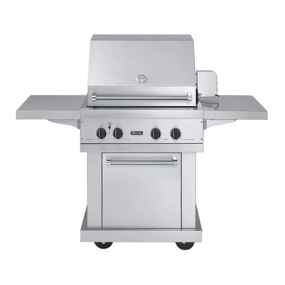
Viking VGBQ300-2RT Installation Manual
30”w. & 41”w. t-series grills
Hide thumbs
Also See for VGBQ300-2RT:
- Specification sheet (8 pages) ,
- Installation instructions manual (18 pages) ,
- Service manual (30 pages)
Advertisement
Quick Links
Advertisement

Summary of Contents for Viking VGBQ300-2RT
- Page 1 Viking Installation Guide Outdoor Gas Grills...
- Page 2 Please Read and Follow! Please Read and Follow! D NGER WARNING WARNING WARNING WARNING WARNING WARNING WARNING CAUTION CAUTION WARNING...
- Page 3 - 1 / ( 7 4 2 ” . 9 c - 5 / ( 4 2 8 ” . 4 c 4 ” - 3 / - 1 / ( 7 4 2 ” . 2 c . 9 c ( 8 3 - 5 / ( 4 2...
- Page 4 53”W. T-Series Grills Description VGBQ530T/VGIQ530T VGBQ532T/VGIQ532T - 3 / ( 7 4 ” - 5 / . 9 c ( 4 2 8 ” . 4 c - 3 / ( 1 3 5 . 1 ” 4 ” - 3 / .
- Page 5 - 1 / ( 7 4 2 ” . 9 c - 5 / ( 4 2 8 ” . 4 c 4 ” - 3 / - 1 / ( 7 4 2 ” . 2 c . 9 c ( 8 3 - 5 / ( 4 2...
- Page 6 - 3 / ( 7 4 ” - 5 / . 9 c ( 4 2 8 ” . 4 c - 3 / ( 1 3 5 . 1 ” Description 4 ” - 3 / . 2 c ( 8 3 VGBQ530E/VGIQ530E VGBQ532E/VGIQ532E...
-
Page 7: For Your Safety
WARNING WARNING DANGER WARNING DANGER CAUTION WARNING DANGER CAUTION DANGER FOR YOUR SAFETY CAUTION CAUTION FOR YOUR SAFETY FOR YOUR SAFETY... - Page 8 - 1 5 / 1 6 ( 5 8 . 3 c ” - 1 / ( 7 4 2 ” 8 ” . 9 c ( 2 0 . 3 c 5 - 3 / 8 ” ( 1 3 - 5 / .
- Page 9 - 1 5 / 1 6 ( 5 8 . 3 c ” - 1 / ( 7 4 2 ” . 9 c - 5 / ( 8 0 8 ” . 2 c - 1 / ( 2 6 4 ”...
- Page 10 Gas inlet and power cord location area ” - 1 / . 1 c ( 1 0 4 ” 2 . 2 ( 7 1 ” ( 9 1 . 4 c * * A - 1 / c c e ( 2 6 4 ”...
- Page 11 Not less than 5.00 inches from inside bottom of countertop. 5.00 inch maximum Vents 5.00 inch 1.00 inch maximum maximum Not less than 1.00 inch from No more than 5.00 inches above inside floor of the floor of the installation. installation.
- Page 12 NOT : If using a Viking GSH12 flexible hose, remove the 1/2” flare adapter and attach hose to the 7/8” (2.2 cm) male flare on the regulator assembly. Male Male Male coupler coupler coupler sleeve sleeve sleeve Installer supplied flexible gas line with 1/2”...
- Page 13 3/8” female 3/8” 3/8” 3/8” flare adapter male male male flare flare flare adapter adapter adapter 3/8” male flare adapter Regulator assembly NOTE: Tank must be mounted in vertical position for proper Ventilation Type 1, QCC-1 connector...
- Page 14 DANGER CAUTION FOR YOUR SAFETY ote: For LP/Propane units, check with a full cylinder. Call an authorized gas appliance service technician or LP/Propane gas dealer. Do not use the grill until the leak is corrected.
- Page 15 CORRECT BLUE LIFTING YELLOW connected to switches on valve panel. replacing the knob, it may be easier to light the burner. NOT : Leave wires CORRECT YELLOW 2 " ( 1 . 8 " ( . 9 BLUE LIFTING NOT : y...
- Page 16 WARNING Groove skewer support Rotisserie motor Mounting bracket Gear box assembly Grounded plug...


Need help?
Do you have a question about the VGBQ300-2RT and is the answer not in the manual?
Questions and answers