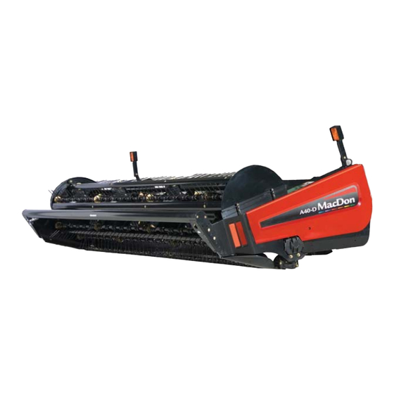
MacDon A40D Operator's Manual
Auger header
Hide thumbs
Also See for A40D:
- Operator's manual (240 pages) ,
- Unloading and assembly instructions (156 pages) ,
- Assembly instructions manual (120 pages)

Subscribe to Our Youtube Channel
Related Manuals for MacDon A40D


Summary of Contents for MacDon A40D
- Page 1 A40D and A40DX Auger Header Operator’s Manual 262334 Revision A Original Instruction The Harvesting Specialists.
- Page 2 © 2023 MacDon Industries, Ltd. The information in this publication is based on the information available and in effect at the time of printing. MacDon Industries, Ltd. makes no representation or warranty of any kind, whether expressed or implied, with respect to the...
- Page 3 EC Declaration of Conformity 262334 Revision A...
- Page 4 262334 Revision A...
- Page 5 262334 Revision A...
- Page 6 262334 Revision A...
- Page 7 STANDARD A40D headers (model year 2017 and later) can be converted to A40DX using conversion kit B5998. Installation of the supplied Reel Speed Sensor kit (MD #318022) is NOT required. GRASS SEED A40D headers (model year 2017 and later) can be converted to A40DX using conversion kit B6384. Installation of the supplied Reel Speed Sensor kit (MD #318022) is REQUIRED.
- Page 8 • Unless otherwise noted, use the standard torque values provided in Chapter 7.1 Recommended Torques, page 233. NOTE: Keep your MacDon publications up-to-date. The most current version can be downloaded from our website (www.macdon. com) or from our Dealer-only site (https://portal.macdon.com) (login required). NOTE: This manual is currently available in English and in Russian.
-
Page 9: Summary Of Changes
Summary of Changes At MacDon, we’re continuously making improvements: occasionally these improvements affect product documentation. The following list provides an account of major changes from the previous version of this document. Section Summary of Change Internal Use Only Throughout manual Added M2 Series Windrower content. - Page 10 Section Summary of Change Internal Use Only Replaced the hazard statement. Technical Publications 4.15 Replacing Skid Shoe Wear Plate, Revised the hazard statement. Technical Publications page 218 Added topic. ECN 55422 5.1.6 Hose Bundle Storage Kit, page 5.1.7 Reel Speed Control Kit, page 226 Added topic.
-
Page 11: Model And Serial Number
Model and Serial Number Record the model number, serial number, and model year of the header in the spaces below. The header serial number plate is located on the top of the left end frame (A). Header Model Number: ____________ Header Serial Number: ____________ Model Year: ______ Figure 1: Header Serial Number Plate Location... -
Page 13: Table Of Contents
3.5 Attaching A40D Auger Headers to M Series Self-Propelled Windrowers............41 3.5.1 Attaching A40D Auger Header to M100 or M105 Self-Propelled Windrower ........... 41 3.5.2 Attaching A40D Auger Header to an M150, M155, or M155E4 Self-Propelled Windrower ......47 3.5.3 Attaching A40D Auger Header to M200 Self-Propelled Windrower ............53 3.5.4 Attaching A40D Auger Header to an M205 Self-Propelled Windrower ........... - Page 14 TABLE OF CONTENTS Adjusting Auger Fore-Aft Position ....................80 Adjusting Vertical Position......................81 3.8.5 Setting Reel Position........................82 Adjusting Reel Fore-Aft Position ....................83 Adjusting Reel Vertical Position ..................... 84 Checking Reel Tine to Header Pan Clearance ................... 86 3.8.6 Setting Tine Aggressiveness ......................87 3.8.7 Adjusting Header Angle.........................
- Page 15 TABLE OF CONTENTS 3.14.6 Raking and Tedding ........................123 3.14.7 Using Chemical Drying Agents ....................123 Chapter 4: Maintenance and Servicing....................125 4.1 Preparing for Servicing ........................125 4.2 Opening/Closing Driveshield......................... 126 4.3 Opening/Closing Endshields ......................... 129 4.4 Adjusting Auger Cover ......................... 130 4.5 Maintenance Requirements .........................
- Page 16 TABLE OF CONTENTS 4.8.10 Adjusting Knife Timing....................... 164 4.9 Header Drive Systems ......................... 167 4.9.1 Header Knife Drive ........................167 Checking/Adjusting V-Belt Tension on Left Side................167 Removing Left V-Belts ....................... 167 Installing Double V-Belts ......................168 Checking and Adjusting Left Timing Belt Tension ................169 Removing Timing Belt from Left Side....................
- Page 17 TABLE OF CONTENTS Chapter 5: Optional Equipment ......................223 5.1 Options and Attachments ........................223 5.1.1 Additional Skid Shoes ......................... 223 5.1.2 Gauge Roller Kit......................... 223 5.1.3 Replacement Reel Bat Kit ......................224 5.1.4 Stub Guard Conversion Kit ......................224 5.1.5 Tall Crop Divider Kit........................
-
Page 19: Chapter 1: Safety
Chapter 1: Safety Understanding and consistently following these safety procedures will help to ensure the safety of those operating the machine and of bystanders. 1.1 Safety Alert Symbols The safety alert symbol indicates important safety messages in this manual and on safety signs on the machine. This symbol means: •... -
Page 20: Signal Words
SAFETY 1.2 Signal Words Three signal words, DANGER, WARNING, and CAUTION, are used to alert you to hazardous situations. Two signal words, IMPORTANT and NOTE, identify non-safety related information. Signal words are selected using the following guidelines: DANGER Indicates an imminently hazardous situation that, if it is not prevented, will result in death or serious injury. WARNING Indicates a potentially hazardous situation that, if it is not prevented, could result in death or serious injury. -
Page 21: General Safety
SAFETY 1.3 General Safety Operating, servicing, and assembling machinery presents several safety risks. These risks can be reduced or eliminated by following the relevant safety procedures and wearing the appropriate personal protective equipment. CAUTION The following general farm safety precautions should be part of your operating procedure for all types of machinery. - Page 22 SAFETY • Wear close-fitting clothing and cover long hair. NEVER wear dangling items such as hoodies, scarves, or bracelets. • Keep all shields in place. NEVER alter or remove safety equipment. Ensure that the driveline guards can rotate independently of their shaft, and that they can telescope freely.
-
Page 23: Operational Safety
SAFETY 1.4 Operational Safety Follow all the safety and operational instructions given in this manual. CAUTION • Follow all safety and operational instructions given in your operator's manual. If you do not have a windrower manual, get one from your Dealer and read it thoroughly. •... -
Page 24: Owner/Operator Responsibilities
• It is your responsibility to read and understand this manual completely before operating the pull-type. Contact your MacDon Dealer if an instruction is not clear to you. • Follow all safety messages in the manual and on safety decals on the machine. -
Page 25: Maintenance Safety
SAFETY 1.6 Maintenance Safety Maintaining your equipment safely requires that you follow the relevant safety procedures and wear the appropriate personal protective equipment for the task. To ensure your safety while maintaining the machine: • Review the operator’s manual and all safety items before operating or performing maintenance on the machine. - Page 26 SAFETY • Wear protective gear when working on the machine. • Wear heavy gloves when working on knife components. Figure 1.10: Personal Protective Equipment 262334 Revision A...
-
Page 27: Hydraulic Safety
SAFETY 1.7 Hydraulic Safety Because hydraulic fluid is under extreme pressure, hydraulic fluid leaks can be very dangerous. Follow the proper safety procedures when inspecting hydraulic fluid leaks and servicing hydraulic equipment. • Always place all hydraulic controls in NEUTRAL before leaving the operator’s seat. -
Page 28: Decommissioning And Disposing Of Agricultural Equipment
SAFETY 1.8 Decommissioning and Disposing of Agricultural Equipment When agricultural equipment is no longer serviceable and needs to be decommissioned and disposed of, recyclable materials including ferrous and non-ferrous metals, rubber, and plastics; fluids such as lubricants, refrigerants, and fuels; and hazardous materials found in batteries, some light bulbs, and electronic equipment must be handled safely and not introduced into the environment. - Page 29 SAFETY • Use appropriate personal protective equipment when removing and handling objects and materials. • Use appropriate personal protective equipment when handling objects with residue from pesticides, fertilizers, or other agricultural chemicals. Follow local regulations when handling and disposing of these objects. •...
-
Page 30: Safety Signs
• If the original part on which a safety sign was installed is replaced, ensure that the repair part displays the current safety sign. • Replacement safety signs are available from your MacDon Dealer. Figure 1.16: Operator’s Manual Decal 1.9.1 Installing Safety Decals Worn or damaged safety decals will need to be removed and replaced. -
Page 31: Safety Sign Locations
SAFETY 1.10 Safety Sign Locations Safety signs are factory-installed in many different locations on the header. Figure 1.17: Left Side of Header A - MD #174632 B - MD #184422 C - MD #166452 D - MD #174436 E - MD #171288 F - MD #184372 G - MD #194464 H - MD #194521... - Page 32 SAFETY Figure 1.19: Right Side of Header A - MD #184422 B - MD #170638 C - MD #166452 Figure 1.20: Decals on Right Side of Header 262334 Revision A...
- Page 33 SAFETY Figure 1.21: Center Deflector A - MD #320514 262334 Revision A...
-
Page 34: Understanding Safety Signs
SAFETY 1.11 Understanding Safety Signs Safety sign decals use illustrations to convey important safety or equipment maintenance information. MD #36651 Driveline entanglement hazard DANGER • A rotating driveline contact can cause death—KEEP AWAY! Do NOT operate without: • Stopping the engine and removing the key before opening the shield. - Page 35 SAFETY MD #166452 Hand and arm entanglement hazard WARNING To prevent injury: • Do NOT operate the machine without the shields in place. • Stop the engine and remove the key from the ignition before opening the shield. Figure 1.24: MD #166452 MD #166466 High-pressure oil hazard WARNING...
- Page 36 SAFETY MD #171281 Hot fluid spray hazard CAUTION To prevent injury: • Do NOT remove fluid fill cap when engine is hot. • Allow engine to cool down before opening fluid fill cap. • Fluid is under pressure and may be hot. Figure 1.27: MD #171281 MD #171288 Auger entanglement hazard...
- Page 37 SAFETY MD #174632 Reel entanglement hazard DANGER To prevent injury from entanglement with the rotating reel: • Stand clear of the header while the machine is running. Figure 1.30: MD #174632 MD #184372 General hazard pertaining to machine operation and servicing DANGER To prevent injury or death from the improper or unsafe operation of the machine:...
- Page 38 SAFETY MD #184422 Hand and arm entanglement hazard WARNING To prevent injury: • Stop the engine and remove the key before opening any shielding. • Do NOT operate the header without the shields in place. Figure 1.32: MD #184422 MD #194464 General hazard DANGER To prevent injury or death:...
- Page 39 SAFETY MD #194521 Auger entanglement hazard DANGER To prevent injury from entanglement with rotating auger: • Stand clear of header while machine is running. • Do NOT operate without shields in place. • Stop engine and remove key before opening shield. General hazard pertaining to machine operation and servicing.
- Page 40 SAFETY MD #304865 Header crushing hazard WARNING To prevent injury or death from the fall of a raised header: • Do NOT lift the header at the marked locations. • Only use locations marked for this purpose to lower the header from the vertical to the horizontal position.
-
Page 41: Chapter 2: Product Overview
The following terms, abbreviations, and acronyms are used in this manual. Table 2.1 Definitions Term Definition MacDon A30S, A30D, A40D, A40DX, standard and Grass Seed auger headers A Series Header American Petroleum Institute American Society of Testing and Materials ASTM... - Page 42 PRODUCT OVERVIEW Table 2.1 Definitions (continued) Term Definition An internally threaded fastener designed to be paired with a bolt O-ring boss: A style of fitting commonly used in port openings on manifolds, pumps, and motors O-ring face seal: A style of fitting commonly used for connecting hoses and tubes. This ORFS style of fitting is also commonly called ORS, which stands for O-Ring Seal RoHS (Reduction of...
-
Page 43: Product Specifications
PRODUCT OVERVIEW 2.2 Product Specifications NOTE: Specifications and design are subject to change without notice, or obligation to revise previously sold units. Table 2.2 A40D and A40DX Auger Header Specifications Cutterbar Effective cutting width 4.3 m (14 ft.) header 4496 mm (14 ft. 9 in.) Effective cutting width 4.9 m (16 ft.) header... - Page 44 PRODUCT OVERVIEW Table 2.2 A40D and A40DX Auger Header Specifications (continued) Delivery opening width 2430 mm (95 11/16 in.) Reel Oval closed section bats with end caps. 6 bats NOTE: Grass Seed Special model has standard seven-bat reel optional 7 bat Steel fingers 6 mm (1/4 in.) diameter...
- Page 45 PRODUCT OVERVIEW Table 2.2 A40D and A40DX Auger Header Specifications (continued) Hydraulic quick couplers Standard Attachments And Accessories Header reversing wrench and guard straightening tool Standard Double Windrow Attachment (DWA) M150/M155/M200/M205 windrowers Optional (non GSS headers only) 262334 Revision A...
-
Page 47: Chapter 3: Operation
Chapter 3: Operation This chapter will describe the operating procedures for the A40D and A40DX Windrower Auger Header. 3.1 Attaching A40DX Auger Header to M2 Series Windrower The header’s hydraulic and electrical multicoupler will need to be connected to the windrower before operation. - Page 48 OPERATION 4. Retrieve hydraulic multicouplers (A) and electrical harness (B) from the header. 5. Route the hose/harness bundle toward the windrower through support (C). Figure 3.2: Hydraulic Hoses in Storage Position 6. Insert hose support (B) into hole (A) in the windrower’s left leg.
- Page 49 OPERATION 12. If a rotary disc header is being replaced by an auger header: Remove hose (A) from storage location (B). Connect hose (A) to knife pressure receptacle (C) on the frame. NOTE: Hose quick disconnect (C) is present only on the following configurations: •...
- Page 50 OPERATION 14. Push latch (A) to unlock platform (B). 1015478 Figure 3.7: Left Platform 15. Pull platform (A) toward the cab until it stops and the latch is engaged. 16. If this is the first time the header is connected to the windrower, calibrate the header.
-
Page 51: Detaching A40Dx Auger Header From M2 Series Windrower
OPERATION 3.2 Detaching A40DX Auger Header from M2 Series Windrower Detaching the A40DX electrical and hydraulic connections from the windrower is a simple procedure because of the multicoupler. Refer to your windrower operator’s manual for procedures to mechanically detach the auger header from the M2 Series Windrower. - Page 52 OPERATION 5. Push latch (A) to unlock platform (B). 1015478 Figure 3.11: Left Platform 6. Pull platform (A) toward the cab until it stops and the latch is engaged. Figure 3.12: Left Platform 7. Remove hose support (A) from the windrower’s left leg. Figure 3.13: Multicoupler 262334 Revision A...
- Page 53 OPERATION 8. Place hydraulics/electrical bundle (A) in the storage position on the header. 9. Detach the header from the windrower. For instructions, refer to your windrower operator’s manual. Figure 3.14: Hydraulics Hoses in Storage Position 262334 Revision A...
-
Page 54: Attaching A40Dx Auger Header To M1 Series Windrowers
IMPORTANT: If attempting to attach an A40D Header to an M1170 or M1240 Windrower, the M1 Series Conversion kit (B5998) or the A40D SP Grass Seed Auger Conversion kit (B6384) must first be installed. These kits include a new manifold and hose bundle required for operation with an M1 Series Windrower, and effectively converts an A40D header into an A40DX header. - Page 55 OPERATION 4. If attaching to a rotary disc-ready windrower, ensure knife drive hose (A) is connected to coupler (B). NOTE: Hose (A) provides power to run the knife/conditioner. 1022401 Figure 3.17: M1170/M1240 – Rotary Disc Header Configured NOTE: M1170, M1170NT, M1170NT5, M2170,and M2170NT Windrowers with standard auger/draper configuration do NOT require the knife drive hose;...
- Page 56 OPERATION 10. Remove the cover from receptacle (A) and connect the electrical harness from the header. Figure 3.20: Windrower Electrical Connector A40DX Grass Seed headers and A40DX headers equipped with Reel Speed Control kit (B6604) A40DX Grass Seed headers have a factory-installed reel speed kit and includes a second electrical connection required for attaching to an M1 or M2 Series Windrower.
-
Page 57: Detaching A40Dx Auger Header From M1 Series Windrower
OPERATION 3.4 Detaching A40DX Auger Header from M1 Series Windrower Follow these steps to detach an A40DX header’s hydraulics and electrical connections from an M1 Series Windrower. Refer to your windrower operator’s manual for procedures to mechanically detach the auger header from the M1 Series Windrower. - Page 58 OPERATION 9. Remove hose support (B) from hole (A) in the windrower left leg, and remove header hose bundle (C) from the windrower. Figure 3.24: Hose Support 10. Keeping hose bundle (A) in hose guide (B), store the hose bundle on top of header walkway (C), away from the windrower.
-
Page 59: Attaching A40D Auger Headers To M Series Self-Propelled Windrowers
M150, M155, M155E4, and M200 Self-Propelled Windrowers with the M Series Reverser kit (B4656) installed need to have the reverser valve hose plumbing changed if switching between a D Series Draper Header with a conditioner to an A40D Auger Header. Changing this plumbing prevents improper operation and damage to the reel drive motor. - Page 60 OPERATION 2. Headers sold in North America: Disengage rubber latch (A) and open driveshield (B). Figure 3.27: Driveshield – Headers Sold in North America 3. Headers sold outside North America: Insert a tool into hole (A) and pry to release latch (B). Disengage rubber latch (C) and open driveshield (D).
- Page 61 OPERATION The driveshield is shown in the open position. Figure 3.29: Driveshield Open 4. Remove cap (A) from the electrical connector and remove the connector from the support bracket. 5. Disengage and rotate lever (B) counterclockwise to the raised position to release the hose bundle (C). Figure 3.30: Support Bracket and Hose Bundle 6.
- Page 62 NOTE: The hoses attached to the connectors are not shown in the illustrations at right. Figure 3.32: A40D Header – 4.3 m and 4.9 m (14 ft. and 16 ft.) Header Shown (5.5 m [18 ft.] Header Similar) A - Reel Pressure...
- Page 63 Figure 3.34: Auger Return and Reel Pressure Hose Bundle 15. If valve blocks are NOT configured as shown (A), install the required fittings as described in the unloading and assembly instructions that were supplied with your A40D Auger Header. Figure 3.35: Valve Block Configuration 262334...
- Page 64 OPERATION 16. Push auger/reel pressure (A) and auger/reel return (B) hose couplers onto the mating receptacles on the valve block until the collar on the receptacle snaps into the lock position. Figure 3.36: Auger/Reel Pressure and Auger/Reel Return Hose Couplers – 4.3 m and 4.9 m (14 ft. and 16 ft.) Header Shown (5.5 m [18 ft.] Header Similar) Figure 3.37: Auger/Reel Pressure and Auger/Reel Return Valve Block Receptacles...
-
Page 65: Attaching A40D Auger Header To An M150, M155, Or M155E4 Self-Propelled Windrower
3.5.6 Routing A40D Auger Header Hydraulic Drive Hoses, page Figure 3.39: Modified Routing M100, M105, and M205 3.5.2 Attaching A40D Auger Header to an M150, M155, or M155E4 Self-Propelled Windrower The header’s hydraulic multicoupler must be connected to the windrower before operation. - Page 66 OPERATION 2. Headers sold in North America: Disengage rubber latch (A) and open driveshield (B). Figure 3.41: Driveshield – Headers Sold in North America 3. Headers sold outside North America: Insert a tool into hole (A) and pry to release latch (B). Disengage rubber latch (C) and open driveshield (D).
- Page 67 OPERATION The driveshield is shown in the open position. Figure 3.43: Driveshield Open 4. Remove cap (A) from the electrical connector and remove the connector from the support bracket. 5. Disengage and rotate lever (B) counterclockwise to the raised position to release hose bundle (C). Figure 3.44: Support Bracket and Hose Bundle 6.
- Page 68 NOTE: The hoses attached to the connectors are not shown in the illustrations at right. Figure 3.46: A40D Header – 4.3 m and 4.9 m (14 ft. and 16 ft.) Header Shown (5.5 m [18 ft.] Header Similar) A - Reel Pressure...
- Page 69 Figure 3.48: Auger Return and Reel Pressure Hose Bundle 15. If valve blocks are NOT configured as shown at right, install the required fittings as described in the A40D and A40DX Auger Header Unloading and Assembly Instructions, which were supplied with your A40D Auger Header.
- Page 70 16. Locate auger pressure (A) and auger/reel return (B) hoses. 17. Proceed to 3.5.5 Configuring Reverser Valve Jumper Hose for A40D Auger Header, page Figure 3.51: Auger Pressure and Auger/Reel Return Hose Couplers – 4.3 m and 4.9 m (14 ft. and 16 ft.) Header Shown (5.5 m [18 ft.] Header Similar)
-
Page 71: Attaching A40D Auger Header To M200 Self-Propelled Windrower
Figure 3.54: Drive Hoses If only three drive hoses are present, before following the procedure below, configure the M200 to run an A40D Auger Header by installing kit B4651. The kit includes an additional hose (A), hardware, and installation instructions. - Page 72 OPERATION 2. Headers sold in North America: Disengage rubber latch (A) and open driveshield (B). Figure 3.56: Driveshield – Headers Sold in North America 3. Headers sold outside North America: Insert a tool into hole (A) and pry to release latch (B). Disengage rubber latch (C) and open driveshield (D).
- Page 73 OPERATION The driveshield is shown in the open position. Figure 3.58: Driveshield Open 4. Remove cap (A) from the electrical connector, and remove the connector from the support bracket. 5. Disengage and rotate lever (B) counterclockwise to the raised position to release hose bundle (C). Figure 3.59: Support Bracket and Hose Bundle 6.
- Page 74 NOTE: The hoses attached to the connectors are not shown in the illustrations at right. Figure 3.61: A40D Header – 4.3 m and 4.9 m (14 ft. and 16 ft.) Header Shown (5.5 m [18 ft.] Header Similar) A - Reel Pressure...
- Page 75 Hose Bundle 15. If valve blocks are NOT configured as shown at right, install the required fittings as described in the unloading and assembly instructions supplied with your A40D Auger Header. Figure 3.64: M200 with Reverser Valve Figure 3.65: M200 without Reverser Valve...
- Page 76 A40D Auger Header. Figure 3.67: M200 with Reverser Valve Figure 3.68: M200 without Reverser Valve 19. Proceed to 3.5.5 Configuring Reverser Valve Jumper Hose for A40D Auger Header, page 262334 Revision A...
-
Page 77: Attaching A40D Auger Header To An M205 Self-Propelled Windrower
OPERATION 3.5.4 Attaching A40D Auger Header to an M205 Self-Propelled Windrower The header’s hydraulic multicoupler must be connected to the windrower before operation. DANGER To prevent injury or death from the unexpected start-up of the machine, always stop the engine and remove the key from the ignition before leaving the operator’s seat for any reason. - Page 78 OPERATION 3. Headers sold outside North America: Insert a tool into hole (A) and pry to release latch (B). Disengage rubber latch (C) and open driveshield (D). Figure 3.71: Driveshield – Headers Sold outside North America The driveshield is shown in the open position. Figure 3.72: Driveshield Open 262334 Revision A...
- Page 79 OPERATION 4. Remove cap (A) from the electrical connector and remove the connector from the support bracket. 5. Disengage and rotate lever (B) counterclockwise to the raised position to release the hose bundle (C). Figure 3.73: Support Bracket and Hose Bundle 6.
- Page 80 • Knife and conditioner return (B) • Case drain (C) • Knife and conditioner pressure (D) Figure 3.75: A40D Hose Connections – 4.9 m (16 ft.) Header Shown Figure 3.76: A40D Hose Connections – 5.4 m (18 ft.) Header Shown 13.
- Page 81 • If attaching the header to an M150, M155, M155E4, or M200, do NOT change the reel pressure connection to the motor, UNLESS switching to windrower models M100, M105, or M205. All model years of A40D / A40D GSS are factory-configured for M150, M155, M155E4, and M200.
-
Page 82: Configuring Reverser Valve Jumper Hose For A40D Auger Header
Figure 3.81: A40D Hose (B) Position (A40D on M200 Shown; M150, M155, and M155E4 Similar) To reroute the jumper hose from the draper header position to A40D position, follow these steps: 1. Move the left windrower platform to the open position to expose the hydraulic valve blocks. -
Page 83: Routing A40D Auger Header Hydraulic Drive Hoses
(CDM). 3.5.6 Routing A40D Auger Header Hydraulic Drive Hoses The A40D Auger Header hydraulic drive hose routing depends on the windrower model to which the header is being attached. A40D Headers are factory-configured for M150, M155, M155E4, and Self-Propelled M200 Windrowers as shown in Figure 3.90, page... - Page 84 OPERATION 3. Headers sold in North America: Disengage rubber latch (A) and open driveshield (B). Figure 3.85: Driveshield – Headers Sold in North America 4. Headers sold outside North America: Insert a tool into hole (A) and pry to release latch (B). Disengage rubber latch (C) and open driveshield (D).
- Page 85 OPERATION The driveshield is shown in the open position. Figure 3.87: Driveshield Open 5. Loosen bulkhead nut (A) on auger and reel pressure coupler (B). This allows auger and reel pressure hose (C) to rotate freely. Figure 3.88: Auger and Reel Pressure Coupler and Hose –...
- Page 86 OPERATION 6. Disconnect the hoses as follows: Disconnect hose (A) from tee (B). b. Disconnect tee (B) from the reel motor upper port. Disconnect hose (C) from the reel motor lower port. 7. Cut cable ties (D) at locations shown in the illustration. Figure 3.90: Factory Configuration –...
- Page 87 OPERATION 9. Secure the hose routing with cable ties (A) as shown. IMPORTANT: Ensure that electrical harness (B) and reel motor case drain hose (C) are secured to hose (D) and that there is at least 25 mm (1 in.) clearance between hose bundle (E) and knife drive timing belt (F).
- Page 88 OPERATION 13. Rotate coupler (B) and hose (C) downward as shown until the slack has been sufficiently reduced. Tighten bulkhead nut (A). Figure 3.93: Auger and Reel Pressure Coupler and Hose – 4.3 m and 4.9 m (14 ft. and 16 ft.) Header Shown Figure 3.94: Auger and Reel Pressure Coupler and Hose –...
- Page 89 OPERATION 15. Headers sold outside North America: Close driveshield (A). Latch (B) will automatically latch. Engage rubber latch (C). 16. Close the driveshield before engaging the header. Figure 3.96: Driveshield – Headers Sold outside North America 262334 Revision A...
-
Page 90: Detaching A40D Auger Header From M Series Self-Propelled Windrower
3.6 Detaching A40D Auger Header from M Series Self-Propelled Windrower Folow this procedure to detach an A40D Auger Header from an M Series Self-Propelled Windrower. DANGER To prevent injury or death from the unexpected start-up of the machine, always stop the engine and remove the key from the ignition before leaving the operator’s seat for any reason. - Page 91 OPERATION Figure 3.99: M150 without Reverser Valve – M155 and M155E4 Similar Figure 3.100: M200 with Reverser Valve Figure 3.101: M200 without Reverser Valve 262334 Revision A...
- Page 92 OPERATION Figure 3.102: M205 3. Raise lever (B) on hose support (C), and undo three adjustable straps (D). 4. Move hose bundle (A) to store on the header walkway. 5. Install the caps on the connectors and the hose ends (if equipped).
- Page 93 • Knife and conditioner return (B) • Case drain (C) • Knife and conditioner pressure (D) Figure 3.104: A40D Hose Connections – 4.9 m (16 ft.) Header Shown Figure 3.105: A40D Hose Connections – 5.4 m (18 ft.) Header Shown 7.
- Page 94 OPERATION 8. Move hose bundle (A) from the header, and position it on the left of the windrower with the hose ends in support (B) and under lever (C). 9. Rotate lever (C) clockwise, and push it to engage the bracket.
-
Page 95: Header Lift Cylinder Lock-Out Valves
OPERATION 3.7 Header Lift Cylinder Lock-Out Valves Refer to your windrower operator’s manual for information about the lift cylinder lock-out valves. 262334 Revision A... -
Page 96: Operating Variables
OPERATION 3.8 Operating Variables Satisfactory function of the header in all situations requires making proper adjustments to suit various crops and conditions. Correct operation reduces crop loss and allows cutting of more acres. As well, proper adjustments and timely maintenance will increase the length of service you receive from the machine. -
Page 97: Adjusting Auger Speed
OPERATION 3.8.2 Adjusting Auger Speed An A40 Auger Header features a hydraulic direct drive auger with operating speed range of 230 to 320 rpm, and is controlled from the operator’s station on the self-propelled windrower. For instructions, refer to your windrower operator’s manual. 3.8.3 Adjusting Reel Speed An A40 Auger Header features a hydraulic direct drive reel with operating speed ranges of 50 to 85 rpm for M100, M105, M200, and M205 Self-Propelled Windrowers, as well as M1170, M1240, M2170, and M2260 Windrower models with... -
Page 98: Adjusting Auger Fore-Aft Position
3. Loosen four nuts (A). 4. Loosen the jam nut on adjuster bolt (B), and turn bolt (B) to adjust the auger fore-aft position. 5. Tighten the jam nut. 6. Tighten nuts (A). Figure 3.110: A40D Left Side 262334 Revision A... -
Page 99: Adjusting Vertical Position
10. Tighten the jam nut. 11. Tighten nuts (A). 12. Close the endshields before engaging the header. Figure 3.111: A40D Right Side Adjusting Vertical Position Follow this procedure to adjust the auger header’s vertical position. WARNING To prevent accidental movement of windrower, return ground speed lever (GSL) to Park, center steering wheel to lock, shut off engine, and remove key. -
Page 100: Setting Reel Position
10. Tighten the jam nut. 11. Tighten nuts (A). 12. Close the endshields before engaging the header. Figure 3.113: A40D Right Side 3.8.5 Setting Reel Position The reel position has been found to be a critical factor in achieving good results in adverse conditions. -
Page 101: Adjusting Reel Fore-Aft Position
OPERATION Adjusting Reel Fore-Aft Position Follow this procedure to adjust the reel fore-aft position. The reel fore-aft offset is factory-set to 816 mm (32 3/8 in.) as measured from the inside edge of the reel tube to the back frame member as shown in the illustration at right. NOTE: The reel must be adjusted equally on both sides. -
Page 102: Adjusting Reel Vertical Position
OPERATION 7. Open the right endshield. 8. Loosen four nuts (A). 9. Loosen the jam nut on adjuster bolt (B), and turn bolt (B) to adjust the reel fore-aft position. 10. Tighten the jam nut. 11. Tighten nuts (A). 12. Close the driveshields before engaging the header. Figure 3.116: Auger Header Right Side Adjusting Reel Vertical Position Follow this procedure to adjust the reel vertical position. - Page 103 OPERATION 4. Loosen the jam nuts on adjuster bolts (A), and turn bolts (A) to raise or lower the reel. 5. Tighten jam nuts (A). Figure 3.118: Auger Header Left Side 6. Tighten nuts (A). Figure 3.119: Auger Header Left Side 7.
-
Page 104: Checking Reel Tine To Header Pan Clearance
OPERATION 9. Loosen the jam nuts on adjuster bolts (A), and turn bolts (A) to adjust the reel vertical position. NOTE: The factory setting at forward adjuster bolt should be 12 mm (15/32 in.) lower than at rear adjuster bolt. If tine aggressiveness has changed, then the adjuster bolt offset may not equal factory settings. -
Page 105: Setting Tine Aggressiveness
OPERATION 1. Rotate the reel slowly by hand, and check the tine clearance at the knife and the pan. Flex the tines to simulate crop-loaded position to ensure the tine clearances to the knife sections and the auger pan are adequate for working conditions. -
Page 106: Adjusting Header Angle
OPERATION 4. Loosen the jam nuts on bolts (A), and turn the bolts to rotate the cam to the desired position. Viewed from the right side, rotate the cam clockwise to obtain more aggressive tine action. NOTE: The factory setting at forward adjuster bolt should be 12 mm (15/32 in.) lower than at rear adjuster bolt. -
Page 107: Setting Cutting Height
OPERATION 3.8.8 Setting Cutting Height Follow this procedure to set the desired cutting height. WARNING To prevent accidental movement of windrower, return ground speed lever (GSL) to Park, center steering wheel to lock, shut off engine, and remove key. 1. Raise the header, and engage the header lift cylinder lock- out valves. -
Page 108: Checking And Adjusting Float - M2 Series Windrowers
OPERATION 3.8.9 Checking and Adjusting Float – M2 Series Windrowers The windrower is equipped with float springs that are fully adjustable with hydraulic cylinders. Spring tension is adjustable ™ from zero to maximum tension through the HarvestTouch Display. The header float feature allows the header to follow the contours of the ground closely as the windrower moves forward. The header is able to respond to sudden changes in elevation or obstacles quickly. -
Page 109: Setting Float - M2 Series Windrowers
OPERATION Setting Float – M2 Series Windrowers The float can be set for windrowing with the cutterbar on the ground. The optimum float setting lets the header follow the contour of the terrain. ™ 1. Set the center-link to the mid-range position (5.0 on the HarvestTouch Display). -
Page 110: Removing And Restoring Float - M2 Series Windrowers
OPERATION 4. Press arrows (A) to adjust left or right float settings. NOTE: Float adjustments of 1.0 (out of 10) change the header weight at the cutterbar by approximately 91 kg (200 lb.). Adjust the float in increments of 0.05 to optimize field performance. -
Page 111: Setting Float Options With Fixed Deck - M2 Series Windrowers
OPERATION ™ 4. Press FLOAT SETTINGS icon (A) on the HarvestTouch Display to show the float setting page. ™ Figure 3.136: HarvestTouch Display 5. Press float switch (A) on the FLOAT ADJUST page to remove or restore the header float. 6. - Page 112 OPERATION 1. Start the engine and use HEADER TILT switches (A) and (B) on the ground speed lever (GSL) to set header tilt to the mid-range position. Figure 3.138: GSL 2. Engage the header by pushing and holding down HEADER ENGAGE switch (A), and pulling up on collar (B).
-
Page 113: Checking And Adjusting Float - M1 And M2 Series Windrowers
OPERATION 4. Disengage the header by pushing down on HEADER ENGAGE switch (A). 5. Adjust the float setting for the selected deck position. For Setting Float – M2 Series Windrowers, instructions, refer to page 6. Repeat the previous steps for the other deck positions. Figure 3.141: Header Engage Switch 3.8.10 Checking and Adjusting Float –... -
Page 114: Setting Float - M1 Series Windrowers
OPERATION Setting Float – M1 7. Restart the engine, and adjust the float as needed. For instructions on adjusting the float, refer to Series Windrowers, page NOTE: Increasing the float makes the header feel lighter. Setting Float – M1 Series Windrowers The float can be set for windrowing with the cutterbar on the ground. -
Page 115: Removing And Restoring Float - M1 Series Windrowers
OPERATION 5. Turn scroll knob (A) to highlight left (B) or right float (C) and press knob (A) to activate the selection. 6. Rotate scroll knob (A) to adjust the float setting and press the knob. NOTE: Float adjustments of 1.0 (out of 10) change the header weight at the cutterbar by approximately 91 kg (200 lb.). -
Page 116: Setting Float Options With Fixed Deck - M1 Series Windrowers
OPERATION Setting Float Options with Fixed Deck – M1 Series Windrowers When an M1 Series Windrower not equipped with the deck shift feature is paired with an A40DX Auger Header, the DECK SHIFT buttons can be used to store three different float settings. This is useful when cutting in varying ground conditions, or when having one side lighter is desirable (such as cutting along wheel tracks or irrigation borders). -
Page 117: Checking And Adjusting Float - M Series Self-Propelled Windrowers
OPERATION 3. Select one of the following deck positions using the DECK SHIFT switches on the operator’s console: • Right-side delivery (A) • Center delivery (B) • Left-side delivery (C) Figure 3.150: Header Deck Shift Switches 4. Disengage the header by pushing down on HEADER ENGAGE switch (A). -
Page 118: Setting Feed Pan And Rock Drop Tine Position
OPERATION 3. Lower the header fully with the lift cylinders fully retracted. 4. Set left and right float fine adjustments to mid-range position (5.0 on the cab display module). For instructions, refer to your windrower operator’s manual. 5. Shut down the engine, and remove the key from the ignition. 6. -
Page 119: Adjusting Conditioner Roll Gap
OPERATION 3. Loosen nut (A) on both sides, and align pointer (B) at each side of the rock drop tine support with one of slots (C) to match the crop condition. Figure 3.153: Rock Drop Tine Support Crop Condition Light Heavy Normal Upper... -
Page 120: Adjusting Conditioner Roll Tension
OPERATION 5. Loosen bolt (A), and rotate cover (B) to expose access port (C). 6. Inspect the space between the roll bars at both ends of the rolls at access port (C). IMPORTANT: Roll timing and alignment are critical when the roll gap is decreased because: •... -
Page 121: Positioning Forming Shields
OPERATION Table 3.2 Conditioner Roll Tension Factory Settings Left spring (A) 81–91 mm (3 3/16–3 9/16 in.) Right spring (B) 41–51 mm (1 5/8–2 in.) WARNING To prevent accidental movement of windrower, return ground speed lever (GSL) to Park, center steering wheel to lock, shut off engine, and remove key. -
Page 122: Positioning Side Deflectors
OPERATION Positioning Side Deflectors The position of the side forming shields controls the width and placement of the windrow. WARNING To prevent accidental movement of windrower, return ground speed lever (GSL) to Park, center steering wheel to lock, shut off engine, and remove key. To ensure windrow placement is centered with respect to carrier/drive wheels, adjust both side deflectors to the same hole position on the adjuster bar. - Page 123 OPERATION 1. Shut down the engine, and remove the key from the ignition. 2. For more crop control in light material, lower rear deflector (A) by pushing down on one side of the deflector, and then on the other side. Locking handles (B) are located at either end of the deflector, and may be loosened slightly.
-
Page 124: Recommended Operating Settings
OPERATION 3.9 Recommended Operating Settings These settings are intended as a starting point. Operators should fine-tune to crop and field conditions. Refer to Table 3.3, page 107. 262334 Revision A... - Page 125 OPERATION 262334 Revision A...
- Page 126 OPERATION 262334 Revision A...
- Page 127 OPERATION 262334 Revision A...
-
Page 128: Recommended Settings And Checks For A40Dx Gss Auger Header
OPERATION 3.9.1 Recommended Settings and Checks for A40DX GSS Auger Header Follow the recommended settings and checks to prevent reel stalling and reduced reel drive performance on A40DX GSS Auger Headers. Ensure the differential auger reel control (DARC) is set up correctly. •... -
Page 129: Unplugging Conditioner And Knife
8. Clean off the cutterbar and the area under the reel by hand. 9. Retrieve wrench (A) from the storage inside the left drive compartment. Figure 3.161: Wrench Location – A40D 262334 Revision A... - Page 130 OPERATION 10. Use the wrench on the left end of primary driveshaft (A) to turn the rolls forward until the plug clears. 11. Return the wrench to the storage location, and secure it in place with a pin. WARNING Return the unplug wrench to the storage location, and close the left driveshield before restarting the machine.
-
Page 131: Grass Seed Special
OPERATION 3.11 Grass Seed Special The grass seed auger header has several features to adapt it to this special application. Some of these features include: • 3.11.1 Stub Guards and Hold-Downs, page 113 • 3.11.2 Special Auger Design for Grass Seed Special, page 114 •... -
Page 132: Special Auger Design For Grass Seed Special
OPERATION 3.11.2 Special Auger Design for Grass Seed Special The center beaters and the beater supports have been removed to reduce auger wrapping. Figure 3.164: Grass Seed Auger 3.11.3 Seven-Bat Reel A seventh bat is added to the reel body, for smoother reel action and better crop feed into the header. Figure 3.165: Grass Seed Reel 262334 Revision A... -
Page 133: Auger Pan Extensions
OPERATION 3.11.4 Auger Pan Extensions The grass seed header is equipped with adjustable auger pan extensions that allow adjustment of delivery opening to vary the windrow characteristics. Installing and Adjusting Pan Extensions Follow this procedure to install the pan extensions. 1. - Page 134 OPERATION 3. Install left deflector (A) using nuts and bolts (B) and nut, bolt, and five washers (C) retained from the previous step. Torque all the nuts to 11.5 Nm (102 lbf·in / 8 lbf·ft). NOTE: Do NOT install nut (D) if the pan extension’s width will be adjusted.
-
Page 135: Windrow Forming Rods
OPERATION 3.11.5 Windrow Forming Rods The forming rods are provided to assist in forming the narrow windrows preferred for this application. Bend the rods to modify the windrow shape. Use the forming rods in conjunction with the auger pan extensions to achieve the width and the shape of the desired windrows. -
Page 136: Selecting Ground Speed
OPERATION 3.12 Selecting Ground Speed Choose a ground speed that allows the knife to cut the crop smoothly and evenly. CAUTION Reduce the speed when turning, crossing slopes, or when travelling over rough ground. Windrower ground speed SHOULD NOT EXCEED 13 km/h (8 mph). For most crop conditions, a ground speed of 8 km/h (5 mph) has been found satisfactory. -
Page 137: Tall Crop Dividers
OPERATION 3.13 Tall Crop Dividers The tall crop dividers attach to the ends of the header for clean crop dividing, and reel entry in tall crops. They can be easily adjusted to suit the crop, or removed when not required. 3.13.1 Adjusting Tall Crop Dividers The tall crop divider can be adjusted by aligning it with the alternate hole location. -
Page 138: Removing Tall Crop Dividers
OPERATION 3.13.2 Removing Tall Crop Dividers Follow these steps to remove the tall crop dividers. 1. Remove U-bolt (A) and bolts (B), and remove the divider. Repeat for the other divider. 2. Remove the bolts attaching the lean bar to the header. Figure 3.174: Tall Crop Divider 3. - Page 139 OPERATION 4. Reposition the lean bar on the header at the desired height, and install existing carriage bolts (A)—two per side. Tighten the bolts. Figure 3.176: Lean Bar 262334 Revision A...
-
Page 140: Haying Tips
OPERATION 3.14 Haying Tips To optimize haying, refer to the variety of processes below in order to best manage the variables of the crop. 3.14.1 Curing Curing crops quickly helps maintain the highest quality of crop material. Approximately 5% of protein is lost from hay for each day that it lays on the ground after cutting. -
Page 141: Driving On Windrow
OPERATION Table 3.5 Recommended Windrow Characteristics Advantage Characteristic Enables airflow through the windrow, which is more important to the curing High and fluffy process than direct sunlight Consistent formation (not bunching) Permits an even flow of material into the baler, chopper, etc. Results in even and consistent bales to minimize handling and Even distribution of material stacking problems... -
Page 143: Chapter 4: Maintenance And Servicing
Chapter 4: Maintenance and Servicing The following instructions are provided to assist you in the use of the header. Detailed maintenance and service information is contained in the technical service manual that is available from your Dealer. A parts catalog is provided with your shipment. -
Page 144: Opening/Closing Driveshield
MAINTENANCE AND SERVICING 4.2 Opening/Closing Driveshield This procedure is for opening and closing the driveshield over the conditioner drivelines. DANGER To prevent injury or death from the unexpected start-up of the machine, always stop the engine and remove the key from the ignition before leaving the operator’s seat for any reason. - Page 145 MAINTENANCE AND SERVICING The driveshield shown in the open position. Figure 4.3: Driveshield Open Closing driveshield 1. Headers sold in North America: Close driveshield (B) and engage rubber latch (A). Figure 4.4: Driveshield – Headers Sold in North America 262334 Revision A...
- Page 146 MAINTENANCE AND SERVICING 2. Headers sold outside North America: Close driveshield (A). Latch (B) will automatically latch. Engage rubber latch (C). Figure 4.5: Driveshield – Headers Sold outside North America 262334 Revision A...
-
Page 147: Opening/Closing Endshields
MAINTENANCE AND SERVICING 4.3 Opening/Closing Endshields This procedure is for opening and closing the endshields at each end of the machine. To open the endshields: CAUTION Ensure shield lock engages in the open position as shown at (B) before letting go of shield. 1. -
Page 148: Adjusting Auger Cover
MAINTENANCE AND SERVICING 4.4 Adjusting Auger Cover Auger covers are installed only on the windrower headers to keep the debris from obstructing the operator’s view. DANGER To prevent bodily injury or death from the unexpected startup of the machine, always stop the engine and remove the key from the ignition before leaving the operator’s seat for any reason. -
Page 149: Maintenance Requirements
MAINTENANCE AND SERVICING 4.5 Maintenance Requirements Periodic maintenance requirements are organized according to service intervals. Regular maintenance is the best insurance against early wear and untimely breakdowns. Following the maintenance schedule will increase your machine’s life. When servicing the machine, refer to the specific headings in this section and use only fluids and lubricants specified in chart on the inside back cover of this manual. -
Page 150: Maintenance Schedule/Record
MAINTENANCE AND SERVICING 4.5.1 Maintenance Schedule/Record Auger Header Maintenance p p - Change S S - Lubricate ü ü - Check Action: Record Hour meter reading Date Serviced by Refer to 4.5.2 Break-in Inspection, page 133. Break-in 100 Hours or Annually Conditioner drive gearbox ü... -
Page 151: Break-In Inspection
MAINTENANCE AND SERVICING Auger Header Maintenance p p - Change ü ü - Check S S - Lubricate Action: Record 1000 Hours or 3 Years Conditioner drive gearbox lubricant Knife drive box lubricant 4.5.2 Break-in Inspection Hours Item Check Reference Torque 7.1 Recommended Torques, page 233 Hardware... - Page 152 MAINTENANCE AND SERVICING 1. Clean the header thoroughly. 2. Store in a dry, protected place if possible. If stored outside, always cover header with a waterproof canvas or other protective material. 3. Raise header, and engage header lift cylinder lock-out valves. 4.
-
Page 153: Lubrication
MAINTENANCE AND SERVICING 4.6 Lubrication Greasing points are marked on the machine by decals showing a grease gun and the grease interval in hours of operation. CAUTION To avoid personal injury, before servicing header or opening drive covers, follow procedures in 4.1 Preparing for Servicing, page 125. -
Page 154: Lubrication Points: Auger Header
Base. To prevent binding and/or excessive wear caused by knife pressing on guards, do NOT over-grease the lubrication points. If more than 6 to 8 pumps of grease gun are required to fill the cavity, replace the seal in the knifehead. Figure 4.9: A40D, A40DX Header Right Side A - Knife Drive Bearing (1 Place) (50 Hours) - Page 155 If more than 6 to 8 pumps of grease gun are required to fill the cavity, replace the seal in the knifehead. Figure 4.10: A40D, A40DX Header Left Side A - Tine Bar Bearing (4 Places Each Tine Bar) (50 Hours)
-
Page 156: Lubrication Points: Hay Conditioner
MAINTENANCE AND SERVICING Lubrication Points: Hay Conditioner There are several points on the hay conditioner which will require lubrication. NOTE: Use high temperature extreme pressure (EP2) performance with 1% max molybdenum disulphide (NLGI Grade 2) lithium base. Figure 4.11: Hay Conditioner A - Roll Pivot (1 Place - Both Sides) B - Roll Shaft Bearings (2 Places) C - Roll Shaft Bearings (2 Places) -
Page 157: Lubrication Points: Drivelines
MAINTENANCE AND SERVICING Lubrication Points: Drivelines There are several points on the drivelines which will require lubrication. NOTE: High Temperature Extreme Pressure (EP2) Performance With 1% Max Molybdenum Disulphide (NLGI Grade 2) Lithium Base. To prevent binding and/or excessive wear caused by knife pressing on guards, do NOT over-grease the lubrication points. -
Page 158: Lubrication Points: Knife And Gearbox
MAINTENANCE AND SERVICING Lubrication Points: Knife and Gearbox There are several points on the knife and the gear which will require lubrication. Refer to the following illustration to identify the various locations that require lubrication. Refer to the inside back cover of this manual for proper oil recommendations. -
Page 159: Installing Sealed Bearings
MAINTENANCE AND SERVICING 4.6.3 Installing Sealed Bearings Sealed bearings are held in place on a shaft with a locking collar and a flangette. Follow these steps to install sealed bearings: 1. Clean the shaft and coat it with rust preventative. 2. -
Page 160: Hydraulics
MAINTENANCE AND SERVICING 4.7 Hydraulics For hydraulics information about self-propelled windrower headers, contact your Dealer. 4.7.1 Servicing Header Hydraulics Refer to your windrower operator’s manual for hydraulic system maintenance procedures for self-propelled windrower headers. 4.7.2 Checking Hoses and Lines Check hydraulic hoses and lines daily for signs of leaks. WARNING •... -
Page 161: Cutterbar
MAINTENANCE AND SERVICING 4.8 Cutterbar This chapter covers maintenance and servicing of the entire cutting assembly. CAUTION To avoid personal injury, before servicing header or opening drive covers, follow procedures in 4.1 Preparing for Servicing, page 125. WARNING Exercise caution when working around the cutterbar. Blades are sharp and can cause serious injury. -
Page 162: Removing Knife
MAINTENANCE AND SERVICING 2. Stroke the knife as required to expose the knife sections. 3. Remove lock nuts (A), and lift section (B) off of the bolts. IMPORTANT: Do NOT mix heavy and light knife sections on the same knife. 4. -
Page 163: Installing Knife
MAINTENANCE AND SERVICING 4.8.3 Installing Knife The cutterbar knife is designed to easily be replaced if worn or damaged. A spare knife can be stored in the lean bar. DANGER To prevent bodily injury or death from the unexpected start-up or fall of a raised machine, always stop the engine and remove the key before leaving the operator’s seat, and always engage the safety props before going under the machine for any reason. -
Page 164: Removing Knifehead Bearing
MAINTENANCE AND SERVICING 4.8.4 Removing Knifehead Bearing The knifehead bearing allows the knifehead pin to rotate within the knifehead as the drive arm strokes the knife back and forth. If the bearing is worn or damaged, it will need to be replaced. 1. -
Page 165: Removing Spare Knife From Storage
MAINTENANCE AND SERVICING 4.8.6 Removing Spare Knife from Storage For double-knife headers, a spare knife with knifehead may be stored inside lean bar (A): • The left knife is stored at the left end of the lean bar. • The right knife is stored at the right end of the lean bar. Figure 4.24: Spare Knife Location –... -
Page 166: Aligning Guard
MAINTENANCE AND SERVICING • Drive End – Located at the drive end of cutterbar, next to outboard guard. Similar to standard but does not have a ledger to allow for slight fore/aft motion from the knife drive box. • Standard – Standard guard used at all other locations. Figure 4.26: Guard Configurations A - Pointed Standard (MD #118344) B - Pointed Drive End (No Ledger) (MD #118345) - Page 167 MAINTENANCE AND SERVICING 2. Retrieve tool (A) from the left side of header. 1017886 Figure 4.27: Wrench Location 3. To adjust guard tips downward, position the tool as shown at right, and push the tool down. Figure 4.28: Guard Tip – Downward Adjustment 4.
-
Page 168: Replacing Pointed Guards And Hold-Downs
MAINTENANCE AND SERVICING Replacing Pointed Guards and Hold-Downs Check daily that guards are firmly bolted to the cutterbar, and not worn or broken. Replace broken guards as required. A worn or broken guard can be replaced without removing knife from cutterbar. This procedure describes the replacement of pointed guards and hold-downs on single- and double-knife headers. - Page 169 MAINTENANCE AND SERVICING Double knife pointed center guard and hold-down IMPORTANT: Ensure center guard (B) has offset (A) in ledgers and that hold- down accommodates overlapping knives. NOTE: Replace adjacent guards when replacing center guard. Figure 4.32: Pointed Center Guard 1.
-
Page 170: Replacing Pointed Center Guard On Double-Knife Header
MAINTENANCE AND SERVICING Replacing Pointed Center Guard on Double-Knife Header Check daily that guards are firmly bolted to the cutterbar, and not worn or broken. Replace the guards as required. A worn or broken guard can be replaced without removing knife from cutterbar. This procedure applies to the center guard where the two knives overlap on a double-knife header. - Page 171 MAINTENANCE AND SERVICING 1. Stroke the knife so that knife sections are spaced midway between the guards. 2. Remove two nuts (A) and bolts (B) that attach center guard (C) and hold-down (D) to cutterbar. 3. Remove guard (C), hold-down (D), and adjuster bar (E). 4.
-
Page 172: Replacing Center Stub Guard On Double-Knife Header
MAINTENANCE AND SERVICING 7. Check clearance between hold-down (D) and section. Refer Adjusting Knife Hold-Down: Center Guard – Double-Knife Header, page 158. Figure 4.38: Pointed Center Guard Figure 4.39: Pointed Guard Identification A - Offsets B - Center Guard C - Normal Guard Replacing Center Stub Guard on Double-Knife Header Check daily that guards are firmly bolted to the cutterbar, and not worn or broken. - Page 173 MAINTENANCE AND SERVICING IMPORTANT: Ensure center guard (A) has offset cutting surface (B). IMPORTANT: Ledger surfaces of center and adjacent guards must be vertically aligned to avoid interference with knife sections. Figure 4.40: Center Guard – Double Knife IMPORTANT: Hold-down (A) must accommodate the two overlapping knives at center guard location on double-knife header.
-
Page 174: Hold-Downs
MAINTENANCE AND SERVICING IMPORTANT: Ensure center guard (B) has offset cutting surfaces. Figure 4.43: Stub Guard Identification A - Normal Guard B - Center Guard NOTE: Top guide (C) (which is an inverted stub guard) must accommodate the two overlapping knives at center guard location on double-knife header. - Page 175 MAINTENANCE AND SERVICING Figure 4.45: Hold-Downs A - Pointed Standard (MD #118162) B - Pointed Center Double Knife (MD #124344) C - Stub Center Double Knife (MD #118346) D - Stub Standard (MD #034359) DANGER To avoid bodily injury or death from the unexpected startup of the machine, always stop the engine and remove the key from the ignition before leaving the operator’s seat for any reason.
-
Page 176: Adjusting Knife Hold-Down: Center Guard - Double-Knife Header
MAINTENANCE AND SERVICING Adjusting Knife Hold-Down: Center Guard – Double-Knife Header To adjust the hold-down at the double-knife center pointed guard, follow the recommended adjustment procedure provided here. 1. Torque nuts (A) to 46 Nm (35 lbf·ft). 2. Turn adjuster bolts (B). Using a feeler gauge, the clearance from the hold-down to knife section (C) should be: •... -
Page 177: Knife Drive Box
MAINTENANCE AND SERVICING 4.8.9 Knife Drive Box The knife drive box converts rotational motion from the windrower header driveshaft to reciprocating motion for the knife. Heavy-duty oil bath knife drive box (A) uses tapered roller bearings on the input shaft and the yoke for increased durability. -
Page 178: Removing Knife Drive Box
MAINTENANCE AND SERVICING Removing Knife Drive Box The knife drive box may need to be removed for repair. 1. Loosen knife drive belt (A), and slip off the knife drive box pulley. Refer to the following sections: • Checking and Adjusting Left Timing Belt Tension, page •... -
Page 179: Installing Knife Drive Box
MAINTENANCE AND SERVICING 9. Remove bolts (A) attaching the knife drive box to the frame. 10. Remove the knife drive box. Figure 4.53: Knife Drive Box Bolts Installing Knife Drive Box To install a knife drive box, follow the recommended installation procedure provided here. 1. - Page 180 MAINTENANCE AND SERVICING 6. Slide pitman arm (C) up or down on the shaft until it just contacts knifehead (B) (0.25 mm [0.010 in.]) gap. 7. Install bolt (E) and nut, and torque the hardware to 217 Nm (160 lbf·ft). 8.
-
Page 181: Removing Knife Drive Box Pulley
MAINTENANCE AND SERVICING Removing Knife Drive Box Pulley To remove the knife drive box pulley, follow the recommended removal procedure provided here. 1. Remove knife drive box. Refer to Removing Knife Drive Box, page 160. 2. Loosen nut and bolt (A) from pulley. 3. -
Page 182: Adjusting Knife Timing
1017917 Figure 4.61: Knife Drive Box Breather 4.8.10 Adjusting Knife Timing Double-knife A40D Auger Headers require that the knives are properly timed to move in opposite directions. Knives moving in the same direction will cause unnecessary vibration. DANGER To prevent injury or death from the unexpected start-up of the machine, always stop the engine and remove the key from the ignition before leaving the operator’s seat for any reason. - Page 183 MAINTENANCE AND SERVICING 3. Rotate the left knife drive box driven pulley (A) clockwise until the left knife is at the center of the inboard stroke (moving towards center of header). NOTE: Center stroke is when the knife points are centered between guard points.
- Page 184 MAINTENANCE AND SERVICING 7. Check for correct knife timing by rotating driveshaft (A) slowly with unplugging wrench (B), and observe where the knives overlap at the center of the header. IMPORTANT: The knives must move in opposite directions, and must begin moving at exactly the same time.
-
Page 185: Header Drive Systems
MAINTENANCE AND SERVICING 4.9 Header Drive Systems The A40D/A40DX Auger Headers has three drive systems: the knife drive, the reel drive, and the auger drive. 4.9.1 Header Knife Drive The A40D and A40DX double-knife headers have a windrower-powered hydraulic motor that drives each knife on the header with two belt-driven knife drive boxes. -
Page 186: Installing Double V-Belts
MAINTENANCE AND SERVICING 3. Loosen three nuts (A) and jam nut on adjuster bolt (B). 4. Turn adjuster bolt (B) so that drive belts (C) can be slipped off pulleys (D) and (E). Figure 4.69: Left V-Belt Installing Double V-Belts To install the double V-belts, follow these steps. -
Page 187: Checking And Adjusting Left Timing Belt Tension
MAINTENANCE AND SERVICING Checking and Adjusting Left Timing Belt Tension To check and adjust the tension of the left timing belt, follow these steps. DANGER To avoid bodily injury or death from the unexpected startup of the machine, always stop the engine and remove the key from the ignition before leaving the operator’s seat for any reason. - Page 188 MAINTENANCE AND SERVICING 5. Loosen three bolts (A) that lock the pulley in position. 6. Loosen adjusting bolt (B); this will loosen the knife drive belt. 7. Remove the two belts (C) that drive the cross shaft. 8. Remove knife drive timing belt (D) from the rear pulley. 1002759 Figure 4.73: Belts Tension Bolts 9.
-
Page 189: Installing Left Timing Belt
MAINTENANCE AND SERVICING Installing Left Timing Belt To install the left timing belt, follow these steps. DANGER To avoid bodily injury or death from the unexpected startup of the machine, always stop the engine and remove the key from the ignition before leaving the operator’s seat for any reason. 1. -
Page 190: Checking And Adjusting Right Timing Belt Tension
MAINTENANCE AND SERVICING 6. Tighten adjuster bolt jam nut (A) and three nuts (B) on the knife drive pulley. 7. Reconnect hoses onto hydraulic motor (C). 8. Install the knife drive V-belts. For instructions, refer to Installing Double V-Belts, page 168. -
Page 191: Removing Right Timing Belt
MAINTENANCE AND SERVICING 3. Apply a force of 22–30 N (5–6.5 lbf) on belt (D) at midspan. The belt should deflect 14 mm (9/16 in.). If necessary, adjust as follows: Loosen three nuts (A) and the jam nut on adjuster bolt (B). -
Page 192: Installing Right Timing Belt
MAINTENANCE AND SERVICING 3. Open the right endshield. 4. Loosen three nuts (A), and the jam nut on adjuster bolt (B). 5. Turn adjuster bolt (B) so that knife drive belt (C) can be slipped off pulley (D). 6. Remove belt (C) from pulley (E) and remove the belt through the hole in the endsheet. -
Page 193: Header Reel Drive
The reel drive gearbox is a sealed, factory-assembled unit on A40D and A40DX Auger Headers. The reel drive gearbox requires no scheduled maintenance, but if service is required, contact your Dealer. 4.9.3 Header Auger Drive The auger on an A40D and A40DX Header is driven directly from a hydraulic motor that is powered by the windrower hydraulics. 262334... -
Page 194: Reel Tines And Tine Bar Bearings
MAINTENANCE AND SERVICING 4.10 Reel Tines and Tine Bar Bearings Separate procedures are required to replace reel tines, depending on their location on the reel. Refer to the following topics for these procedures: • 4.10.1 Replacing Tine and Bearing: Cam End – Disc #1, page 176 •... - Page 195 MAINTENANCE AND SERVICING 2. Remove cam follower bearing bolt (A), bearing (B), and nut. 3. Disengage cam arm (C) from the cam track with a pry bar. 4. Remove flangette mounting bolts (D). Figure 4.88: Cam Follower 5. Remove nuts (A), keepers (B), and shoulder bolts (C) that connect cam arm (D) and end tines (E) to the tine bar.
- Page 196 MAINTENANCE AND SERVICING 7. Replace bearing (A). Refer to 4.6.3 Installing Sealed Bearings, page 141. Figure 4.91: Cam Arm Assembly 8. Replace the tines as follows: Remove bolt (A) and keeper (B) on tine to be replaced. b. Remove the bolts and the keepers on the tines as required to facilitate the replacement of the damaged or worn tine.
- Page 197 MAINTENANCE AND SERVICING IMPORTANT: Replace the hardware at the cam end of the tine bar with the hardware as specified in the following steps. 13. Position the tines as shown and install bolts (A) with the keepers, spacers (B), and nuts (C). 14.
-
Page 198: Replacing Tine And Bearing: Disc #2
MAINTENANCE AND SERVICING 17. Reposition cover (A) on the cam, and tighten the bolt. Figure 4.97: Cover 4.10.2 Replacing Tine and Bearing: Disc #2 Follow the provided procedure to properly replace the tines and the bearings at disc #2. Replace tine and bearing at disc #2 (A) as follows: The location of disc #2 (A) is shown on the illustration at right. - Page 199 MAINTENANCE AND SERVICING Type A tine bars 1. Remove flangette mounting bolts (A) at reel disc #2. 2. Remove shoulder bolts (B) and keeper (C) from the tine bar. 3. Separate left tine bar (D) with bearing from center tine bar (E).
- Page 200 MAINTENANCE AND SERVICING 8. Install end tines (G) onto left tine bar (F) with shoulder bolts (D), keepers (E), and nuts (C). 9. Assemble new bearing (A) with flangettes onto connecting shaft (B). Refer to 4.6.3 Installing Sealed Bearings, page 141.
- Page 201 MAINTENANCE AND SERVICING 17. Remove bearing (A) from tine bar connecting shaft (B). Refer to 4.6.3 Installing Sealed Bearings, page 141. 18. Remove nut (C), shoulder bolt (D), and keeper (E) from left tine bar (F) and remove tine (G). Figure 4.105: Tine Bar Type B 19.
-
Page 202: Replacing Tine And Bearing: Center Section X
MAINTENANCE AND SERVICING 22. Slip the new tine onto center tine bar (E). 23. Assemble left tine bar (D) to center tine bar (E) and secure it with shoulder bolt (B) and nut. 24. Secure the tine onto center tine bar (E) with shoulder bolt (B), keeper (C), and nut. - Page 203 MAINTENANCE AND SERVICING 2. Remove shoulder bolts (B) and keeper (C) connecting tine bar sections X and Y at reel disc #3. 3. Lift the tine bar away from the reel arms, and remove complete tine bar section Y (including reel bearings at discs #3 and #4).
-
Page 204: Replacing Tine And Bearing: Opposite Cam - Section Y
MAINTENANCE AND SERVICING 8. Attach the bearing flangettes to the reel arm at discs #3 and #4 with bolts (A). Tighten the bolts to 31–36 Nm (23–26 lbf·ft). Figure 4.114: Disc #4 4.10.4 Replacing Tine and Bearing: Opposite Cam – Section Y Follow the provided procedure to properly replace the tines and the bearings on the opposite cam at section Y. - Page 205 MAINTENANCE AND SERVICING 1. Remove shoulder bolts (A) and keeper (B) connecting tine bar sections Z and Y at reel disc #4. 2. Remove flangette mounting bolts (C) at reel disc #4. 3. Lift the tine bar away from the reel arms, and remove complete tine bar section Z, complete with the bearing assembly.
-
Page 206: Replacing Tine: Tine Bar Extension - Section Z
MAINTENANCE AND SERVICING 7. Install shoulder bolts (A) and keeper (B) with the tine to connect the tine bar extension. 8. Install flangette mounting bolts (C) at reel disc #4. Tighten the bolts to 21–27 Nm (16–20 lbf·ft). Figure 4.118: Disc #4 A - Shoulder Bolts B - Keeper C - Flangette Mounting Bolts... - Page 207 MAINTENANCE AND SERVICING 1. Remove bolt (A) and keepers (B) on the tine to be replaced, and slide the tines off the tine bar. Figure 4.120: Disc #4 A - Bolt B - Keepers Z - Section Z 2. Install the tines on the tine bar, and secure them with bolt (A) and two keepers (B).
-
Page 208: Straightening Auger Pans
MAINTENANCE AND SERVICING 4.11 Straightening Auger Pans The high density polyethylene auger pans are repairable and replaceable. Refer to your Dealer for details on replacing the pans. IMPORTANT: To prolong the life of the auger pan, be sure to check that the reel tines do NOT contact the pans when adjusting the reel position or the tine pitch. -
Page 209: Replacing Rubber Fingers
MAINTENANCE AND SERVICING 4.12 Replacing Rubber Fingers Rubber fingers should be replaced if they are missing or damaged. To replace a rubber finger, follow these steps: 1. Remove nut and bolt (A), and then remove finger (B). 2. Position the new finger in the holder, and then install the bolt and nut. -
Page 210: Stripper Bar
MAINTENANCE AND SERVICING 4.13 Stripper Bar Stripper bars help prevent the crop from wrapping around the auger and improve crop flow into the conditioner. To maintain 1–4 mm (1/32–5/32 in.) clearance (B) between auger (A) flighting and stripper bars, bars may need replacing due to wear or damage. -
Page 211: Replacing Stripper Bars
MAINTENANCE AND SERVICING 4.13.2 Replacing Stripper Bars To replace the stripper bars, follow these steps. DANGER To avoid bodily injury or death from the unexpected start-up or fall of a raised machine, shut down the engine, remove the key, and engage the safety props before going under the machine. 1. - Page 212 MAINTENANCE AND SERVICING 2. Raise the header, and engage the safety props. 3. Remove the nuts and carriage bolts (A) securing two extensions (B) to the underside of the header pan support. Retain the hardware for reinstallation. Figure 4.126: Stripper Bar Extension 4.
-
Page 213: Conditioner
MAINTENANCE AND SERVICING 4.14 Conditioner Conditioner rolls condition the crop by crimping and crushing the stem in several places, which allows the release of moisture, resulting in faster crop drying times. CAUTION To avoid personal injury, before servicing header or opening drive covers, follow procedures in 4.1 Preparing for Servicing, page 125. - Page 214 MAINTENANCE AND SERVICING 4. Place a suitable container under the gearbox drain to collect the oil. 5. Remove breather (A) and check plug (B). Figure 4.129: Gearbox Breather Figure 4.130: Check Plug 6. Remove drain plug (A) and allow the oil to drain. Replace the drain plug once the oil has drained.
-
Page 215: Removing Forming Shield
MAINTENANCE AND SERVICING 7. Add oil at (A) to the required level. Refer to the inside back cover for the recommended lubricant. Figure 4.132: Gearbox Breather NOTE: The oil is at the required level when it runs out of check plug (B). - Page 216 MAINTENANCE AND SERVICING 2. Remove hairpins (B), and the washers that secure straps (A) to the frame. 3. Hold onto the forming shield, and slip the straps off the pins. Lower the forming shield to the ground. Figure 4.134: Forming Shield Straps 4.
-
Page 217: Disassembling Forming Shield
MAINTENANCE AND SERVICING 4.14.3 Disassembling Forming Shield Follow this procedure to disassemble the forming shield. 1. Invert the forming shield onto top. 2. Remove lynch pin (A) from adjuster rods (B), and remove the rods from side deflectors (C). Figure 4.136: Forming Shield 3. -
Page 218: Assembling Forming Shield
MAINTENANCE AND SERVICING 4. Remove locking handles (A), and remove the bolts. 5. Remove fluffer shield (B) from the forming shield cover. Figure 4.138: Cover 6. Remove bolts (A) to remove deflector fins (B) from the cover. Figure 4.139: Cover 4.14.4 Assembling Forming Shield The deflector fins, fluffer shield, locking handle,, and side deflectors will need to be secured to the forming shield cover. - Page 219 MAINTENANCE AND SERVICING 2. Attach fluffer shield (B) to the forming shield cover. 3. Attach locking handles (A) to the forming shield cover with bolts. Figure 4.141: Cover 4. Attach side deflectors (C) and washers (D) to the forming shield cover with nuts (A) and bolts (B). Figure 4.142: Forming Shield 262334 Revision A...
-
Page 220: Installing Forming Shield
MAINTENANCE AND SERVICING 5. Attach adjuster rods (B) to side deflectors (C) with lynch pin (A). Figure 4.143: Forming Shield 4.14.5 Installing Forming Shield Follow this procedure when installing the forming shield. NOTE: Forming shields are not compatible with narrow transport windrowers. 1. - Page 221 MAINTENANCE AND SERVICING 3. Remove two clevis pins (A) from the forward end of the forming shield. Figure 4.146: Forming Shield 4. Position forming shield (A) under the windrower frame. Figure 4.147: Forming Shield under the Windrower 262334 Revision A...
- Page 222 MAINTENANCE AND SERVICING 5. Position the forming shield onto bolts (A) in the windrower legs and secure the forming shield with clevis pins (B) and hairpin. Figure 4.148: Forming Shield Attached to the Windrower Legs 6. Lift the aft end of the forming shield and attach straps (B) to pins (A) on the windrower frame.
-
Page 223: Removing Header Drive Motor
Figure 4.150: Side Deflectors and Fluffer Shield 4.14.6 Removing Header Drive Motor This procedure applies to A40D and A40DX Auger Headers (excluding Grass Seed A40D and Grass Seed A40DX). DANGER To avoid bodily injury or death from the unexpected startup of the machine, always stop the engine and remove the key from the ignition before leaving the operator’s seat for any reason. -
Page 224: Installing Header Drive Motor
Figure 4.152: Header Drive Motor 4.14.7 Installing Header Drive Motor This procedure applies to A40D and A40DX Auger Headers (excluding Grass Seed A40D and Grass Seed A40DX). DANGER To avoid bodily injury or death from the unexpected startup of the machine, always stop the engine and remove the key from the ignition before leaving the operator’s seat for any reason. -
Page 225: Removing Conditioner Gearbox
MAINTENANCE AND SERVICING 3. Apply a light coat of silicone to the motor flange. 4. Position the motor on the gearbox, as shown, until the mounting holes are aligned, and the pinion engages the gear in the gearbox. 5. Clean off the excess sealant from the motor flange and the gearbox face. - Page 226 MAINTENANCE AND SERVICING 3. Remove two bolts (A) securing channel (B) to the frame. Figure 4.156: Conditioner Drive 4. Remove two hex bolts (A), and one carriage bolt (B) securing channel (C) to the endsheet and remove channel (C). Figure 4.157: Header Drive 5.
- Page 227 MAINTENANCE AND SERVICING 7. Remove two bolts (A) in upper driveline (B). 8. Pull driveline (B) off the gearbox. If necessary, use a screwdriver or equivalent to spread the yoke. Move the driveline out of the work area. 9. Remove four bolts (C) from flange on lower driveline (D) and remove driveline from gearbox.
-
Page 228: Installing Conditioner Gearbox
MAINTENANCE AND SERVICING 4.14.9 Installing Conditioner Gearbox Follow this procedure to install the conditioner drive gearbox. DANGER To avoid bodily injury or death from the unexpected startup of the machine, always stop the engine and remove the key from the ignition before leaving the operator’s seat for any reason. 1. - Page 229 MAINTENANCE AND SERVICING 4. Locate key (A) in the shaft. 5. Place pulley (B) onto the shaft. Figure 4.164: Gearbox Pulley 6. Place tapered bushing (A) onto shaft, align it with key (B) in the shaft and push bushing (A) into place. 7.
- Page 230 MAINTENANCE AND SERVICING 12. Remove oil level check plug (A) in the gearbox. If the oil does not run out of the plug, add oil to the required level. If oil is required, refer to the chart on the inside back cover of this manual.
-
Page 231: Checking/Adjusting Roll Alignment
MAINTENANCE AND SERVICING 19. Position channel (B) against the endsheet as shown, picking up the three holes in the endsheet. 20. Install two carriage bolts and nuts (A) in the lower two holes. Figure 4.170: Conditioner Drive 21. Install the carriage bolt and nut in upper hole (B) with the head facing inboard. - Page 232 MAINTENANCE AND SERVICING 3. Open driveshield (A). For instructions, refer to 4.2 Opening/ Closing Driveshield, page 126. Figure 4.172: Driveshield 4. Locate roll alignment cover (A). Figure 4.173: Roll Alignment Cover 5. Loosen bolt (A), and rotate cover (B) to expose the access port.
- Page 233 MAINTENANCE AND SERVICING 6. Examine roll bar spacing (X) at each end of the rolls. The rolls are aligned if (X) varies less than 1.6 mm (1/16 in.) from one end to the other. Figure 4.175: Roll Bar Spacing 7. If roll bar spacing (X) (as shown in Step 6, page 215) varies more than 1.6 mm (1/16 in.), align the rolls as follows:...
-
Page 234: Checking And Adjusting Roll Timing
MAINTENANCE AND SERVICING 4.14.11 Checking and Adjusting Roll Timing The rolls must be correctly timed with each steel bar on one roll centered between two bars of the other roll. DANGER To avoid bodily injury or death from fall of raised machine, always lock-out lift cylinders before going under header for any reason. - Page 235 MAINTENANCE AND SERVICING 5. Examine roll spacing (X) at each end of the rolls. Each steel bar on one roll should be centered between two bars of the other roll so that distance (X) is 12 mm (1/2 in.). NOTE: If distance (X) varies more than 1.6 mm (1/16 in.) from one end to the other, the rolls should be realigned.
-
Page 236: Replacing Skid Shoe Wear Plate
MAINTENANCE AND SERVICING 4.15 Replacing Skid Shoe Wear Plate Skid shoes are equipped with replaceable wear plates that can be reversed for increased service life. It is recommended that wear plates be replaced when the skid shoe support bracket becomes exposed. DANGER To avoid bodily injury or death from the unexpected start-up or fall of a raised machine, always shut down the engine and remove the key before leaving the operator’s seat, and always engage the safety props or close the lock-out valves... - Page 237 MAINTENANCE AND SERVICING 8. Insert the tabs on the skid shoe into slots (A) on the cutterbar at the inboard mounting locations on the frame, and secure the tabs with clevis pin (B). Figure 4.185: Inboard Cutterbar Mounting Location 9. Reinstall clips (A) with the bolts and nuts removed from Step 3, page 218 to secure the skid shoe to the cutterbar.
-
Page 238: Gauge Rollers
MAINTENANCE AND SERVICING 4.16 Gauge Rollers Gauge rollers can be removed for replacement or repair. 4.16.1 Removing Gauge Rollers The gauge rollers can be removed for replacement or repair. DANGER To prevent bodily injury or death from the unexpected start-up or fall of a raised machine, always stop the engine and remove the key before leaving the operator’s seat, and always engage the safety props before going under the machine for any reason. - Page 239 MAINTENANCE AND SERVICING 2. Secure the gauge roller assembly with two pins (B) at the lowest position. 3. Attach clips (A) with the bolts and nuts to secure the roller assembly to the cutterbar. NOTE: Use a socket and ratchet wrench to access the nuts. 4.
-
Page 240: Maintaining The Electrical System
To replace the light bulbs, follow these steps: 1. Using a Phillips screwdriver, remove screws (A) from the fixture, and remove the plastic lens. 2. Replace the bulb, and reinstall the plastic lens and the screws. Figure 4.191: A40D Hazard Light 262334 Revision A... -
Page 241: Chapter 5: Optional Equipment
Chapter 5: Optional Equipment The following options and attachments are available for use with your header. See your MacDon Dealer for availability and ordering information. 5.1 Options and Attachments 5.1.1 Additional Skid Shoes In addition to the standard skid shoes, two additional skid shoes may be added for extra control of cutting height and protection of cutting components. -
Page 242: Replacement Reel Bat Kit
OPTIONAL EQUIPMENT 5.1.3 Replacement Reel Bat Kit This kit consists of one complete bat assembly for ease of replacement. Separate kits are available for different header widths: • 4.3 m (14 ft.): B4716 • 4.9 m (16 ft.): B4717 • 5.5 m (18 ft.): B4718 Figure 5.3: Reel Bat Assembly 5.1.4 Stub Guard Conversion Kit Stub guards, complete with top guides and adjuster plates are designed to cut tough crops. -
Page 243: Tall Crop Divider Kit
OPTIONAL EQUIPMENT 5.1.5 Tall Crop Divider Kit Tall crop dividers attach to the ends of the header for clean crop dividing and reel entry in tall crops. The kit includes left and right dividers, lean bar extensions and attachment hardware. B4690 Figure 5.5: Tall Crop Divider (Left Side) 5.1.6 Hose Bundle Storage Kit... -
Page 244: Reel Speed Control Kit
OPTIONAL EQUIPMENT 5.1.7 Reel Speed Control Kit The Reel Speed Control kit is required to provide the variable reel speed function on the A40DX and A40DX Grass Seed (GSS) Header. B6604 or MD #318001 Figure 5.7: Reel Speed Control Kit 262334 Revision A... -
Page 245: Chapter 6: Troubleshooting
Chapter 6: Troubleshooting A troubleshooting table is provided to help you diagnose and correct any problems you may encounter while operating your machine. 6.1 Header Performance A troubleshooting table is provided to help you diagnose and correct any problems you may encounter regarding the header performance. - Page 246 TROUBLESHOOTING Problem Solution Section Lower the cutting height with 3.8.8 Setting Cutting Height, Cutting height too high skid shoes. page 89 3.12 Selecting Ground Speed, Ground speed too fast Slow down. page 118 Header angle too flat for guards to pick 3.8.7 Adjusting Header Angle, Increase the header angle.
- Page 247 TROUBLESHOOTING Problem Solution Section 3.8.11 Checking and Adjusting Float – M Series Self-Propelled Header float too heavy Adjust to lighter float setting. Windrowers, page 99 — Wet undergrowth Cut when the undergrowth is dry. Move the reel back and down (close to 3.8.5 Setting Reel Position, page Reel position incorrect guards).
- Page 248 TROUBLESHOOTING Problem Solution Section Symptom: Auger plugging in heavy grass seed Remove the lower stripper bar and the Poor crop flow across auger 4.13 Stripper Bar, page 192 middle stripper bar if necessary. Symptom: Plugging at the delivery opening in heavy grass seed Move the pan extensions to the widest 3.11 Grass Seed Special, page Opening too narrow...
-
Page 249: Mechanical
TROUBLESHOOTING 6.2 Mechanical A troubleshooting table is provided to help you diagnose and correct any problems you may encounter regarding the mechanical aspect of the machine. Section Problem Solution Symptom: Auger and/or conditioner rolls damaged by stones 3.8.12 Setting Feed Pan and Feed pan doesn't allow stones to fall Lower the rock-drop tines. - Page 250 TROUBLESHOOTING Problem Solution Section Symptom: Knocking in knife drive 4.8.4 Removing Knifehead Replace. Worn needle bearing in knifehead Bearing, page 146 Worn knifehead pin Replace. 4.8.3 Installing Knife, page 145 Incorrect end guards Replace with special end guards. 4.8.7 Guards, page 147 Symptom: Knife back breakage 4.8.4 Removing Knifehead Replace.
-
Page 251: Chapter 7: Reference
Chapter 7: Reference The reference chapter provides additional information such as the torque specification and a unit conversion chart. 7.1 Recommended Torques The following tables provide torque values for various bolts, cap screws, and hydraulic fittings. Refer to these values only when no other torque value has been specified in a given procedure. - Page 252 REFERENCE Table 7.2 SAE Grade 5 Bolt and Grade F Distorted Thread Nut Torque (Nm) Torque (lbf·ft) (*lbf·in) Nominal Size (A) Min. Max. Min. Max. 1/4-20 16.7 18.5 5/16-18 *149 *164 3/8-16 7/16-14 1/2-13 9/16-12 5/8-11 3/4-10 Figure 7.2: Bolt Grades 7/8-9 A - Nominal Size B - SAE-8...
-
Page 253: Metric Bolt Specifications
REFERENCE Metric Bolt Specifications Specifications are provided for the appropriate final torque values to secure various sizes of metric bolts. NOTE: The torque values provided in the following metric bolt torque tables apply to hardware installed dry; that is, hardware with no grease, oil, or threadlocker on the threads or heads. -
Page 254: Metric Bolt Specifications - Cast Aluminum
REFERENCE Table 7.7 Metric Class 10.9 Bolts and Class 10 Free Spinning Nut Torque (Nm) Torque (lbf·ft) (*lbf·in) Nominal Size (A) Max. Max. Min. Min. 3-0.5 3.5-0.6 4-0.7 5-0.8 6-1.0 14.3 15.8 *140 *154 8-1.25 10-1.5 12-1.75 Figure 7.7: Bolt Grades 14-2.0 16-2.0 20-2.5... -
Page 255: Flare-Type Hydraulic Fittings
REFERENCE Table 7.9 Metric Bolt Bolting into Cast Aluminum Bolt Torque Nominal 10.9 Size (A) (Cast Aluminum) (Cast Aluminum) lbf·ft lbf·ft – – – – – – – – – – – Figure 7.9: Bolt Grades – – – – Flare-Type Hydraulic Fittings The standard torque values are provided for flare-type hydraulic fittings. -
Page 256: O-Ring Boss Hydraulic Fittings - Adjustable
REFERENCE Table 7.10 Flare-Type Hydraulic Tube Fittings (continued) Torque Value Flats from Finger Tight (FFFT) Thread Size (in.) SAE Dash Size Swivel Nut or lbf·ft Tube Hose 1 1/16–12 113–124 83–91 1 1/2 1 1/4 1 3/16–12 136–149 100–110 1 1/2 1 1/4 1 5/16–12 160–176... - Page 257 REFERENCE 5. Install fitting (B) into the port until backup washer (D) and O-ring (A) contact part face (E). 6. Position the angle fittings by unscrewing no more than one turn. 7. Turn lock nut (C) down to washer (D) and tighten it to the torque value indicated in the table.
-
Page 258: O-Ring Boss Hydraulic Fittings - Non-Adjustable
REFERENCE O-Ring Boss Hydraulic Fittings – Non-Adjustable The standard torque values for non-adjustable hydraulic fittings are provided. If a procedure specifies a different torque value for the same type and size of fitting found in this topic, use the value specified in the procedure instead. 1. - Page 259 REFERENCE 1. Ensure that the sealing surfaces and the fitting threads are free of burrs, nicks, scratches, and any foreign material. Figure 7.14: Hydraulic Fitting 2. Apply hydraulic system oil to O-ring (B). 3. Align the tube or hose assembly so that the flat face of sleeve (A) or (C) comes into full contact with O-ring (B).
-
Page 260: Tapered Pipe Thread Fittings
REFERENCE Table 7.13 O-Ring Face Seal (ORFS) Hydraulic Fittings (continued) Torque Value Thread Size (in.) Tube O.D. (in.) SAE Dash Size lbf·ft 1 11/16 1 1/4 205–226 151–167 1 1/2 315–347 232–256 2 1/2 510–561 376–414 Tapered Pipe Thread Fittings The standard torque values are provided for tapered pipe thread fittings. -
Page 261: Conversion Chart
REFERENCE 7.2 Conversion Chart This manual uses both SI units (including metric) and US customary units (sometimes referred to as standard units) of measurement. A list of those units along with their abbreviations and conversion factors is provided here for your reference. -
Page 263: Index
See hydraulic motors M200 ............53 conversion chart ..........243 A40D windrower header cutting heights detaching A40D from windrower ......72 setting............... 89 A40DX auger header attaching to M1 Series windrower ...... 36 detaching from M1 Series windrower ....39 detaching from M2 Series windrower .... - Page 264 (fixed deck only) ......93 setting cutting height ........... 89 removing and restoring float ......92, 97 gearboxes setting float ..........91, 96 A40D conditioner drive gearbox header operation installing ............210 header float removing............207 float operating guidelines......91, 96...
- Page 265 A40D header......... 53 removing............146 M205 SP windrowers unplugging conditioner and knife ......111 attaching A40D auger header ........ 59 knife drive belts maintenance and servicing........125 windrower header See also maintenance adjusting left timing belt tension ...... 169 break-in inspection..........
- Page 266 100 adjusting ............79 float reel tines and tine bar bearings M Series ............. 99 A40D SP windrower header replacing – disc #2 ......... 184 M1 Series............ 95 replacing opposite cam – section Y ....186 M2 Series............ 90 replacing tine bar extension –...
- Page 267 ........ 242 troubleshooting ........... 227 header performance .......... 227 mechanical issues..........231 unplugging conditioner and knife ......111 weather .............. 122 windrower headers attaching A40D to M Series SP windrower ......41 A40DX to M1 Series windrower ......36...
-
Page 269: Recommended Fluids And Lubricants
Recommended Fluids and Lubricants Your machine can operate at top efficiency ONLY if clean lubricants are used. • Use clean containers to handle all lubricants. • Store in an area protected from dust, moisture, and other contaminants. Specification Description Capacities Lubricant High temperature extreme pressure (EP2) performance... - Page 270 CUSTOMERS M M a a c c D D o o n n . . c c o o m m DEALERS P P o o r r t t a a l l . . M M a a c c D D o o n n . . c c o o m m Trademarks of products are the marks of their respective manufacturers and/or distributors.
Need help?
Do you have a question about the A40D and is the answer not in the manual?
Questions and answers