Table of Contents
Advertisement
Quick Links
Advertisement
Table of Contents

Related Manuals for SIKA UC RTD.2


Summary of Contents for SIKA UC RTD.2
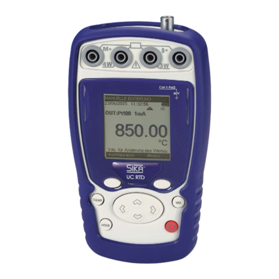
- Page 1 Operating manual Operating manual ..........page 1 - 46 Monofunction simulator Type UC RTD.2 Please keep this operating manual for future reference. If the device is resold, please provide the operating manual along with it.
-
Page 2: Table Of Contents
Parameters ....................... 29 4.5.5 Display burst ..................... 29 4.5.6 Save burst ......................32 4.5.7 Open a burst ..................... 32 4.5.8 New free burst ....................32 4.5.9 Burst management.................... 32 4.5.10 Statistics ......................32 © SIKA • Ba_UC-RTD.2_en • 01/2019 - 2 -... - Page 3 UC RTD.2 4.6 Synthesiser configuration ..................33 4.6.1 Configuration of synthesiser points ..............33 4.6.2 Configuration of synthesiser parameters ............33 4.7 Configuration of the ramp generation ..............34 4.7.1 Incremental signal configuration ................ 34 4.7.2 Single ramp signal configuration ............... 35 4.7.3...
-
Page 4: About This Operating Manual
If you have any problems or questions, please contact your supplier or contact us directly at: Dr. Siebert & Kühn GmbH & Co. KG Struthweg 7-9 • D - 34260 Kaufungen +49 5605 803-0 • +49 5605 803-555 info@sika.net • www.sika.net © SIKA • Ba_UC-RTD.2_en • 01/2019 - 4 -... - Page 5 90 days. This guarantee only applies to the original purchaser or to the end user if the latter is a distributor authorised by SIKA, and it does not apply to fuses, inter-changeable batteries or any product which, according to SIKA, has been tampered with, modified, neglected or damaged by accident or subjected to abnormal conditions of use and handling.
- Page 6 UC RTD.2 Contents checks The UC RTD.2 was checked mechanically and electrically prior to despatch. The necessary precau- tions have been taken to ensure it reaches the user without being damaged. Nonetheless, it is wise to perform a rapid check to detect any deterioration which may have occurred during transport.
-
Page 7: General
It makes it possible to measure and to simu- late temperatures both on site as well as in a laboratory. The UC RTD.2 features a large number of related functions which extend its range of application, in- cluding: •... -
Page 8: Environmental Conditions
The device was designed to operate safely if the instructions provided in the accompanying docu- ments are followed. Any other use may jeopardise the safety of the operator. Any use other than those specified in the instructions is therefore dangerous and forbidden. © SIKA • Ba_UC-RTD.2_en • 01/2019 - 8 -... -
Page 9: Making Measurements
CAT II 60V: The notion of categories determines the maximum transient voltage that can be applied to the meas- urement inputs (it is also called overvoltage category). For the SIKA UC RTD.2, the maximum per- missible overvoltage is 60V (DC or AC) POL 2: The notion of pollution determines the clearance between circuits. -
Page 10: Maintenance
All adjustments, maintenance and repair work on the open device must be avoided as much as pos- sible and, when these are indispensable, they must be performed by qualified staff, who are well aware of the risks involved. © SIKA • Ba_UC-RTD.2_en • 01/2019 - 10 -... -
Page 11: Using The Instrument
UC RTD.2 Using the instrument Using the instrument In order to use the device in all the safety required, all operators must read the paragraph on safety carefully, along with the paragraph below. 2.1 Power-up The device is delivered with 4 AA batteries of 1.5V each. It is wise to place these batteries in the compartment provided for this purpose. -
Page 12: Measuring And Simulation Terminals
HOLD Navigation 2.1.2 Measuring and simulation terminals The UC RTD.2 is fitted with 4 safety bushes (4 mm in diameter) ad a circular 4-point connector. This wiring is used both in measurement and emission mode (non-simultaneous). 3-wire voltage / measurement... - Page 13 UC RTD.2 Using the instrument Measurement Input 2-wire measurement 3-wire measurement 4-wire measurement NOTE: An adjustment of 2, 3 or 4 wire measurement is not necessary. The numbers of wires will be detected automatically. Measurement: Measurement: (positive) (negative) 4-wire voltage /...
-
Page 14: Usb Connector
USB port (mini B connector) 2.1.4 Screen The UC RTD.2 is fitted with a graphic LCD display with back-lighting. The display resolution is 160 x 160 pixels. In normal operating conditions, the display is divided up into seven horizontal fields: •... -
Page 15: Getting Started (After Power-Up)
UC RTD.2 Using the instrument The table below provides a definition of each pictogram displayed on the screen: Symbol Description Emission mode in increases Emission mode in single ramp Emission mode in cyclic ramp Scaling On hold Filtering... -
Page 16: Operating Modes
Scaling 2.1.6.3 Electrical characteristics not to be exceeded. Function Range max V measurement Ω 400 Ω / 3600 Ω 60 V measurement Ω 400 Ω / 3500 Ω 5 mA simulation © SIKA • Ba_UC-RTD.2_en • 01/2019 - 16 -... -
Page 17: Mode Programming
UC RTD.2 Mode Programming Mode Programming 3.1.1 Resistance or temperature measurement using resistive sensors • The choice of measurement or emission mode is made using the F2 key (mode menu). • Using the navigation keys (↑ and ↓), position the cursor in the Measurement field going down the menu. -
Page 18: Resistance Or Temperature Simulation Using Resistive Sensors
The function type selection (Resistive sensor type) and the choice of unit displayed is made using the F1 key (configuration menu) as in the measurement mode (please refer to the previous chapter). © SIKA • Ba_UC-RTD.2_en • 01/2019 - 18 -... - Page 19 UC RTD.2 Mode Programming However, in simulation mode, when using an alternating current transmitter, you must indicate this to the device. • In the CONFIGURATION/MEASURE menu, position the cursor in the Current field using the F1 key. • Enter the Current menu using the F2 key.
- Page 20 Using the navigation key (), you can increase manually the resistance (or temperature) emit- ted (following the parameters programmed in the (CONFIGURATION/RAMP menu). • Using the navigation key (), you can decrease manually the resistance (or temperature) emitted starting from the max. programmed resistance. © SIKA • Ba_UC-RTD.2_en • 01/2019 - 20 -...
- Page 21 UC RTD.2 Mode Programming 3.1.2.4 Single ramp editing • Press the F2 key to display the edit menu. • Using the navigation keys (↑ and ↓), choose the SINGLE RAMP mode and confirm (VAL key). The values emitted are those programmed in the CONFIGURATION/RAMP menu a) automatically •...
- Page 22 The Hold key allows you to stop generating or to resume it. You can resume the generation of the ramp in step-by-step mode by pressing the navigation keys ( and ) or in automatic generation using the navigation keys (↑ and ↓). © SIKA • Ba_UC-RTD.2_en • 01/2019 - 22 -...
-
Page 23: Related Functions
UC RTD.2 Related Functions Related Functions 4.1 Scaling (linearisation) The scale correction function performs conversion operations between the electrical values measured and the physical values converted. This linearisation operation makes it possible to correct partially the errors induced by non-linear sensor/converter systems. -
Page 24: Nulling (Tare/Offset)
The NULLING/Define menu makes it possible to program the value of the Tare (positive or negative). This value is obtained from the measurements: Value Displayed = Value measured – Value of the Tare © SIKA • Ba_UC-RTD.2_en • 01/2019 - 24 -... -
Page 25: Calibrated Sensors (Point Correction)
UC RTD.2 Related Functions 4.3 Calibrated sensors (point correction) The calibrated sensors function of the device makes it possible to use sensors, the calibration (correc- tion) coefficients of which are taken into consideration by the device during measurement. • Using the F1 key, enter the Configuration menu. - Page 26 The calibrated sensors are at the top of the list and their name is preceded by a *. • Confirm the latter using the VAL key. The chosen calibrated sensor is displayed in the measurement screen. Name of calibrated sensor used © SIKA • Ba_UC-RTD.2_en • 01/2019 - 26 -...
-
Page 27: Configuration Predefined Set Points
UC RTD.2 Related Functions 4.4 Configuration predefined set points The configuration of predefined set points is performed in the Configuration/Points menu, obviously providing the default values mode has been confirmed. • Using the F1 key, select the Configuration/Points menu. •... -
Page 28: Storage Of Acquisitions In Progress
Related Functions UC RTD.2 4.5 Storage of acquisitions in progress The UC RTD.2 is designed to store 10000 measuring values in one or more acquisition bursts. • Using the F2 key, enter the Mode menu. • Select the Memory function. -
Page 29: Run
UC RTD.2 Related Functions 4.5.2 Run Launches the storage of data following the parameters set in the “parameters” function. The picto- gram is displayed on the measurement screen 4.5.3 Stop Stops the storage in progress. 4.5.4 Parameters Allows you to define: •... - Page 30 Press the F2 key twice (…), to reach the GRAPH function, then press F2 to confirm. At this level, you can display the whole curve or a zoom around the cursor. The cursor is moved using the navigation keys( and ) © SIKA • Ba_UC-RTD.2_en • 01/2019 - 30 -...
- Page 31 UC RTD.2 Related Functions • Press CLEAR to return to the table of values. At this level, you can find out some statistics on the measurements made (Min, Max, Avg (Average) and Ect (Shift)). • Press the F2 key three times (…) followed by the F1 key (STAT).
-
Page 32: Save Burst
Allows you to display all the bursts recorded. At this level, you can delete one or all bursts. 4.5.10 Statistics Allows you to find out the number of bursts recorded, the number of bytes free as well as the number of measurements which can be recorded. © SIKA • Ba_UC-RTD.2_en • 01/2019 - 32 -... -
Page 33: Synthesiser Configuration
UC RTD.2 Related Functions 4.6 Synthesiser configuration 4.6.1 Configuration of synthesiser points The configuration of the synthesiser points is identical to that of the default values. 4.6.2 Configuration of synthesiser parameters The configuration of the synthesiser parameters is performed in the Configura- tion/Synthesiser/Parameters menu, obviously providing the Synthesiser mode has been confirmed. -
Page 34: Configuration Of The Ramp Generation
The delay corresponds to the amount of time you can have between pressing the emission start key and the actual starting of generation. It is expressed in seconds and the max time is limited to 1000s. © SIKA • Ba_UC-RTD.2_en • 01/2019 - 34 -... -
Page 35: Single Ramp Signal Configuration
UC RTD.2 Related Functions • The CONFIGURATION/RAMP menu is accessed using key F2. • Use the F2 key to move to the next field. • Use the navigation keys to enter the value: o As a percentage of the gauge if the scaling mode is ON. -
Page 36: Cyclic Ramp Signal Configuration
As a percentage of the gauge if the scaling mode is ON. o In ohm or in temperature units if the scaling mode is OFF and according to the type of value emitted (resistance or temperature simulation). © SIKA • Ba_UC-RTD.2_en • 01/2019 - 36 -... - Page 37 UC RTD.2 Related Functions b) Low Level Duration, Rise, High Level Duration, Fall and Delay The low duration, rise, high duration, fall and delay durations are expressed in seconds. The max du- ration is limited to 1000s. c) Repetition The repetitions field indicates the number of ramps that need to be generated. The number of repetiti- ons is limited to 1000.
-
Page 38: Parameter Settings
Use the navigation keys (↑ and ↓) to increase the various parameters. • Use the navigation keys ( and ) to go to the next field. • Press VAL to confirm. © SIKA • Ba_UC-RTD.2_en • 01/2019 - 38 -... -
Page 39: Preferences" Setting
UC RTD.2 Parameter settings 5.3 “Preferences” setting 5.3.1 Filtering setting In the event of noisy measurements, you can filter the latter to make the value displayed on the screen more stable. • Access this menu using the F1 key (configuration menu). -
Page 40: Key Beeping Setting
Using the navigation keys (↑ and ↓), select the desired unit • Confirm by pressing the VAL key. 5.4 Maintenance menu Not accessible to the user: Consult SIKA who will indicate the procedure to follow for maintenance services. © SIKA • Ba_UC-RTD.2_en • 01/2019 - 40 -... -
Page 41: About The Instrument Menu
UC RTD.2 Parameter settings 5.5 About the instrument menu In the Configuration/About menu, you can find out: • The Serial number • The software version • The date of adjustement • The date of calibration Technical changes reserved - 41 -... -
Page 42: Technical Specifications
Automatic wiring diagram detection: 2 wires, 3 wires or 4 wires. • In the 2-wire assembly, the measurement includes the line resistances. • In the 3-wire assembly, add the line resistances imbalance. • Measurement current 0.65 mA © SIKA • Ba_UC-RTD.2_en • 01/2019 - 42 -... -
Page 43: Temperature By Resistive Sensors (Measurement)
UC RTD.2 Technical specifications 6.1.2 Temperature by resistive sensors (measurement) Sensor Scope of measurement Resolution Precision -220°C up to 850 °C 0.01 °C 0.012 % of rdg. + 0.06 °C Pt 50 (α = 3851) Pt 100 (α = 3851) -220°C up to 850 °C... -
Page 44: Temperature By Resistive Sensors (Simulation)
These specifications are given for a measurement current of 0.1 mA to 1mA in direct current mode. 6.3 Power supply - Autonomy The SIKA UC RTD.2 is designed to function either with four 1.5V AA batteries or with a 4.8V battery pack. The following autonomies are given for information. - Page 45 UC RTD.2 For your notes Technical changes reserved - 45 -...
- Page 46 UC RTD.2 Sensors and Measuring Instruments Flow Measuring Instruments Test and Calibration Instruments SIKA Dr. Siebert & Kühn GmbH & Co. KG Struthweg 7–9 34260 Kaufungen Germany +49 5605 803-0 +49 5605 803-555 info@sika.net www.sika.net © SIKA • Ba_UC-RTD.2_en • 01/2019...
Need help?
Do you have a question about the UC RTD.2 and is the answer not in the manual?
Questions and answers