Table of Contents
Advertisement
Available languages
Available languages
Quick Links
Betriebsanleitung
Betriebsanleitung .................................................... Seite 1 - 16
Operating manual .................................................. page 17 - 32
Notice d'utilisation ................................................. page 33 - 48
Niveauwächter
Baureihen VH... / VK...
Bewahren Sie diese Betriebsanleitung zum Nachschlagen auf.
Geben Sie diese Betriebsanleitung bei der Veräußerung des Gerätes mit.
(Original)
Advertisement
Chapters
Table of Contents

Related Manuals for SIKA VH Series


Summary of Contents for SIKA VH Series
- Page 1 Betriebsanleitung (Original) Betriebsanleitung ............ Seite 1 - 16 Operating manual ..........page 17 - 32 Notice d'utilisation ..........page 33 - 48 Niveauwächter Baureihen VH... / VK... Bewahren Sie diese Betriebsanleitung zum Nachschlagen auf. Geben Sie diese Betriebsanleitung bei der Veräußerung des Gerätes mit.
-
Page 2: Table Of Contents
Weitergabe sowie Vervielfältigung dieser Betriebsanleitung, Verwertung und Mitteilung seines Inhalts sind verboten, soweit nicht ausdrücklich gestattet. Zuwiderhandlungen verpflichten zu Schadenersatz. Alle Rechte für den Fall der Patent-, Gebrauchsmuster- oder Geschmacksmustereintragung vorbe- halten. - 2 - © SIKA • Ea1300_LevelSwitch • 06/2017... -
Page 3: Hinweise Zur Betriebsanleitung
Dr. Siebert & Kühn GmbH & Co. KG Struthweg 7-9 • D - 34260 Kaufungen 05605-803 0 • 05605-803 54 info@sika.net • www.sika.net Verwendete Gefahrenzeichen und Symbole: GEFAHR! Lebensgefahr durch elektrischen Strom! Dieses Zeichen kennzeichnet Gefahren, die zu schweren gesundheitlichen Schäden oder zum Tode führen. -
Page 4: Gerätebeschreibung
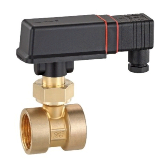
Gerätebeschreibung VH... / VK... Gerätebeschreibung Die SIKA-Niveauwächter sind zur Minimum- bzw. zur Maximumüberwachung von Flüssig- keitsfüllständen vorgesehen. Bauteile Niveauwächter : Funktionsprinzip: Abb. 1 Abb. 2 Das steigende Niveau im Behälter treibt den Schwimmer (5) auf. Über das Wippenstangen- system (1) ändert der Magnet (2) seine Stellung zum Reedkontakt (3) und betätigt diesen. Die Abstoßung zwischen den gleich gepolten Dauermagneten (2) und (4) unterstützt dabei den... -
Page 5: Niveauwächterausführung Vh
VH... / VK... Gerätebeschreibung 1.1.1 Niveauwächterausführung VH...X Die Niveauwächter für den Einsatz im Ex-Bereich besitzen an der letzten Stelle der Artikel- nummer ( Typenschild) ein "X". Sie sind einer Zündgefahrenbewertung entsprechend DIN EN 13463-1 bzw. DIN EN ISO 80079-36 unterzogen worden und besitzen keine eigenen potenziellen Zündquellen. -
Page 6: Sicherheitshinweise
Um die sichere Bedienung zu gewährleisten, ist sachkundiges und sicherheitsbewusstes Verhalten der Bediener erforderlich. SIKA gewährt persönlich oder durch entsprechende Literatur Hilfestellung für die Anwen- dung der Produkte. Der Kunde prüft die Einsetzbarkeit des Produktes auf der Basis unserer technischen Informationen. Mit dieser Prüfung gehen Gefahr und Risiko auf den Kunden über;... -
Page 7: Zusätzlich Gilt Für Niveauwächter Vh
VH... / VK... Materialspezifikationen der benetzten Bauteile Wenn das zu überwachende Medium sehr hohe Temperaturen besitzt, wird auch der Ni- veauwächter extrem heiß. Vermeiden Sie Berührungen und stellen Sie keine temperatur- empfindlichen Gegenstände in der Nähe ab. Schützen Sie den Niveauwächter vor magnetischen Fremdfeldern in der unmittelbaren Umgebung, da diese die Funktionsweise des Gerätes beeinträchtigen können. -
Page 8: Einbau Des Niveauwächters
Bei der Zoneneinteilung ist die Dichtheit der Verschraubungselemente zu berücksichti- gen. Entsprechend den Einsatzbedingungen kann es daher erforderlich sein, die Ver- schraubungselemente regelmäßig auf ihre Dichtheit hin zu überprüfen - 8 - © SIKA • Ea1300_LevelSwitch • 06/2017... -
Page 9: Elektrischer Anschluss
VH... / VK... Elektrischer Anschluss Elektrischer Anschluss 5.1 Allgemeine Hinweise zum elektrischen Anschluss GEFAHR! Lebensgefahr durch elektrischen Strom! Der elektrische Anschluss des VH... / VK... darf nur von einer Elektrofachkraft vorge- nommen werden. Schalten Sie die elektrische Anlage spannungsfrei, bevor Sie den VH... / VK... anschließen. VORSICHT! Zerstörung oder Beschädigung des Reedkontaktes! Die auf dem Typenschild angegebene max. -
Page 10: Sensorstecker M12X1 (4-Polig)
Reedkontakt blau Reedkontakt grün Potential- /gelb ausgleich* Abb. 13 * Zur Vermeidung von elektrostatischer Aufladung müssen Sie die Geräte der Ausführung VH60...X über die feste Anschlussleitung an den Potenzialausgleich anschließen. - 10 - © SIKA • Ea1300_LevelSwitch • 06/2017... -
Page 11: Verstellen Der Schalteinheit
VH... / VK... Verstellen der Schalteinheit Verstellen der Schalteinheit Wichtige Hinweise! Bei kundenseitig gewünschter Schaltpunktfesteinstellung ab Werk entfällt das Verstellen der Schalteinheit. Wenn keine Pfeile auf der Schalteinheit sind, ist ein Verstellen der Kontaktart oder des Schaltpunktes nicht zulässig. 6.1 Kontaktart Die Schalteinheit des Niveauwächters ermöglicht zwei verschiedene Kontaktarten: 1. -
Page 12: Niveauwächterausführung Vh60
Nach der Einstellung des Schaltpunktes empfehlen wir die Arretierungsschraube mit Lack oder Schraubensicherungslack zu sichern. Abb. 18 Bei kundenseitig gewünschter Schaltpunktfesteinstel- lung ab Werk entfällt das Verstellen der Schalteinheit. - 12 - © SIKA • Ea1300_LevelSwitch • 06/2017... -
Page 13: Wartung Und Reinigung
Der VH... / VK... besteht aus unterschiedlichen Werkstoffen ( § 3). Er darf nicht zu- sammen mit Hausmüll entsorgt werden. Führen Sie den VH... / VK... der lokalen Wieder- verwertung zu oder schicken Sie den VH... / VK... an Ihren Lieferanten bzw. SIKA zurück. Technische Änderungen vorbehalten - 13 -... -
Page 14: Technische Daten
Die Zündenergie der explosionsfähigen Atmosphäre darf 60 µJ nicht unterschreiten. Die wirksamen inneren Induktivitäten und Kapazitäten sind vernachlässigbar klein. 10 Zulassungen Die SIKA-Niveauwächter sind vom TÜV Rheinland bauartgeprüft, Prüfzeichen R 60118029 vom 11.04.2017 (gilt nicht für Ausführung mit Sensorstecker M12x1 und nicht für VH...X). - 14 -... -
Page 15: Eg-Konformitätserklärung
VH... / VK... EG-Konformitätserklärung 11 EG-Konformitätserklärung Technische Änderungen vorbehalten - 15 -... - Page 16 VH... / VK... Mess- und Sensortechnik Durchflussmesstechnik Test- und Kalibriertechnik SIKA Dr. Siebert & Kühn GmbH & Co. KG Struthweg 7–9 D-34260 Kaufungen Germany +49 (0)5605 803-0 +49 (0)5605 803-54 info@sika.net www.sika.net - 16 - © SIKA • Ea1300_LevelSwitch • 06/2017...
- Page 17 Operating manual (Translation) Betriebsanleitung ............ Seite 1 - 16 Operating manual ..........page 17 - 32 Notice d'utilisation ..........page 33 - 48 Level Switches Series VH... / VK... Please keep this operating manual for future reference. If the device is resold, please provide the operating manual along with it.
- Page 18 Offenders will be held liable for the payment of damages. All rights reserved in the event of the grant of a patent, utility model or design. - 18 - © SIKA • Ea1300_LevelSwitch • 06/2017...
-
Page 19: About This Operating Manual
Dr. Siebert & Kühn GmbH & Co. KG Struthweg 7-9 • D - 34260 Kaufungen 05605-803 0 • 05605-803 54 info@sika.net • www.sika.net Hazard signs and other symbols used: DANGER! Risk of death due to electric current! This sign indicates dangers which could lead to serious health defects or to death. -
Page 20: Device Description
Device description VH... / VK... Device description SIKA level switches are designed for the monitoring of minimum or maximum liquid filling levels. Components level switch: Functional principle: Fig. 2 Fig. 1 The rising level in the tank forces the float (5) upwards. Via the rocker bar system (1) the magnet (2) changes its position in relation to the reed contact (3) and activates it. -
Page 21: Level Switch Version Vh
VH... / VK... Device description 1.1.1 Level switch version VH...X The level switches for application in explosion-hazardous area have an “X” at the end of the article number ( type plate). They have been subjected to an ignition hazard assessment in according to DIN EN 13463-1 resp. -
Page 22: Safety Instructions
Any internal regulations of the operator must also be complied with, even if these are not mentioned in this manual. To avoid damages to the level switch and the monitored system, only use the SIKA level switch to monitor the filling level of liquids. -
Page 23: Additional Information For The Vh
VH... / VK... Material specifications of wetted components If the medium which is to be monitored is very hot, the level switch will also become ex- tremely hot. In this case, neither touch the level switch nor place any heat-sensitive ob- jects in its vicinity. -
Page 24: Level Switch Installation
Always consider the sealing of the screwing elements Fig. 4 for the zone allocation. Depending on the operating conditions, it may be necessary to regularly check the sealing of the screwing elements. - 24 - © SIKA • Ea1300_LevelSwitch • 06/2017... -
Page 25: Electrical Connection
VH... / VK... Electrical connection Electrical connection 5.1 General electrical connection information DANGER! Risk of death due to electric current! The electrical connection should only be carried out by a fully qualified electrician. Always de-energise the VH... / VK... before connecting the wires of the connecting cable. CAUTION! Destruction or damage of reed contact! The max. -
Page 26: Sensor Plug M12X1 (4-Pole)
Reed contact Reed contact green Equipotential- /yellow bonding* Fig. 13 *) To prevent electrostatic charging the VH…X devices have to be connected to the equipotential bonding via the fixed connecting cable. - 26 - © SIKA • Ea1300_LevelSwitch • 06/2017... -
Page 27: Adjusting The Switching Unit
VH... / VK... Adjusting the switching unit Adjusting the switching unit Important notices! Adjustment of the switching unit is not required if a desired ex works switching point set- ting has been agreed with the customer. If there are no arrows on the switching unit, the Adjustment of the type of contact and the switching point is not permitted. -
Page 28: Level Switch Version Vh60
Adjustment of the switching unit is not required if a de- Fig. 18 sired ex works switching point setting has been agreed with the customer. - 28 - © SIKA • Ea1300_LevelSwitch • 06/2017... -
Page 29: Maintenance And Cleaning
The VH... / VK... consists of various different materials ( § 3). It must not be disposed of with household waste. Take the VH... / VK... to your local recycling plant send the VH... / VK... back to your supplier or to SIKA. Technical changes reserved - 29 -... -
Page 30: Technical Data
The effective internal inductances and capacities are negligibly small. 10 Approvals SIKA level switches are type approved by TÜV Rheinland, certification no. R 60118029, issued on 11.04.2017 (does not apply for version with M12x1 sensor plug and not for VH…X). -
Page 31: Ec Declaration Of Conformity
VH... / VK... EC declaration of conformity 11 EC declaration of conformity Technical changes reserved - 31 -... - Page 32 VH... / VK... Sensors and Measuring Instruments Flow Measuring Instruments Test and Calibration Instruments SIKA Dr. Siebert & Kühn GmbH & Co. KG Struthweg 7–9 D-34260 Kaufungen Germany +49 (0)5605 803-0 +49 (0)5605 803-54 info@sika.net www.sika.net - 32 - ©...
- Page 33 Notice d'utilisation ( Traduction ) Betriebsanleitung ............ Seite 1 - 16 Operating manual ..........page 17 - 32 Notice d'utilisation ..........page 33 - 48 Contrôleur de niveau Séries VH... / VK... Conservez cette notice d'utilisation pour vous y reporter. Joignez cette notice d'utilisation à...
- Page 34 Tout manquement à cette règle est illicite et expose son auteur au versement de dommages et intérêts. Tous droits réservés pour le cas de la délivrance d'un brevet, d'un modèle d'utilité ou d'un modèle de présentation. - 34 - © SIKA • Ea1300_LevelSwitch • 06/2017...
-
Page 35: Indications Sur La Notice D'utilisation
Dr. Siebert & Kühn GmbH & Co. KG Struthweg 7-9 • D - 34260 Kaufungen 05605-803 0 • 05605-803 54 info@sika.net • www.sika.net Signes et symboles de sécurité utilisés : DANGER ! Danger de mort par électrocution ! Ce signe indique un danger susceptible d'entraîner de graves blessures ou même la mort. -
Page 36: Description De L'appareil
Description de l'appareil VH... / VK... Description de l'appareil Les contrôleurs de niveau SIKA sont destinés au contrôle des minima et maxima des niveaux de liquides. Composants contrôleur de niveau: Principe de fonctionnement: Système de Ecrou-raccord tige à bascule Tête de commutation avec l’unité... -
Page 37: Modèle De Contrôleur De Niveau Vh
VH... / VK... Description de l'appareil 1.1.1 Modèle de contrôleur de niveau VH...X Le dernier caractère de la référence des contrôleurs de niveau conçus pour le domaine Ex est un « X » ( plaque signalétique). Les contrôleurs ont été soumis à une évaluation du risque d’allumage selon DIN EN 13463-1 resp. -
Page 38: Consignes De Sécurité
Afin d’éviter les dégâts du contrôleur de niveau et de l'installation à contrôler, il faut tenir compte du fait que les contrôleurs de niveau SIKA sont exclusivement conçus pour le contrôle de niveaux de liquides. Il faut absolument respecter les indications de montage du contrôleur de niveau. -
Page 39: Conditions Supplémentaires Pour Le Contrôleur De Niveau Vh
VH... / VK... Spécification des matériaux des composants mouillés Si le milieu à contrôler présente une température très élevée, les contrôleurs de niveau et leurs raccords deviennent aussi très chauds. Evitez tout contact et éloignez les objets sensibles aux températures élevées. Protégez le contrôleur de niveau des champs magnétiques externes dans l’environnement proche car ils peuvent altérer le fonctionnement de l'appareil. -
Page 40: Montage Du Contrôleur De Niveau
Il faut tenir compte de l’étanchéité des éléments de vissage lors de la détermination des zones. Selon les conditions de l’application, il peut être nécessaire de vérifier régulière- ment l’étanchéité des éléments de vissage. - 40 - © SIKA • Ea1300_LevelSwitch • 06/2017... -
Page 41: Branchement Électrique
VH... / VK... Branchement électrique Branchement électrique 5.1 Généralités sur le branchement électrique DANGER ! Danger de mort par électrocution ! Le raccordement électrique du contrôleur de niveau doit être effectué par un profes- sionnel de l'électricité. Effectuer le installation électrique sans tension avant de raccorder les fils sur le circuit. ATTENTION ! Destruction ou endommagement du contact reed ! Les charges max., qui sont indiquées sur la plaque signalétique, sont uniquement va- lables pour des charges purement ohmiques et ne doivent en aucun cas être dépassées. -
Page 42: Prise Du Capteur M12X1 (À 4 Pôles)
Reed vert compensation /jaune de potentiel* Fig. 13 *) Afin d’éviter les charges électrostatiques, vous devez connecter les appareils à la compensation de potentiel par le câble de connexion fixe. - 42 - © SIKA • Ea1300_LevelSwitch • 06/2017... -
Page 43: Régler L'unité De Commutation
VH... / VK... Régler l’unité de commutation Régler l’unité de commutation Indications importants! Si le client souhaite que le réglage fin du point de commutation soit effectué en usine, le réglage de l’unité de commutation n’est pas à faire. S'il n'y a aucune flèche sur l'unité de commutation, une modification du type de contact ou du point de commutation n'est pas autorisée. -
Page 44: Modèle De Contrôleur De Niveau Vh60
Fig. 18 Si le client souhaite que le réglage fin du point de commutation soit effectué en usine, le ré- glagede l’unité de commutation n’est pas à faire. - 44 - © SIKA • Ea1300_LevelSwitch • 06/2017... -
Page 45: Entretien Et Nettoyage
Le VH... / VK... se compose de différents matériaux ( § 3). Il ne peut pas être jetée en- semble avec les déchets ménagers. Emportez le VH... / VK... à votre centre local de re- cyclage renvoyez le VH... / VK... à votre fournisseur ou à SIKA. Sous réserve de modifications techniques - 45 -... -
Page 46: Données Techniques
60 µJ. Les inductions et capacités internes effectives sont négligeables. 10 Homologations Les modèles de contrôleur de niveau SIKA sont homologués par le contrôle technique TÜV de Rhénanie, estampille de contrôle R 60118029 du 11.04.2017 (ne s'applique pas au modèle avec connecteur de capteur M12x1). -
Page 47: 11 Déclaration De Conformité Ue
VH... / VK... Déclaration de conformité UE 11 Déclaration de conformité UE Sous réserve de modifications techniques - 47 -... - Page 48 Flow Measuring Instruments Instruments de mesure de débit Test und Kalibriertechnik Test and Calibration Instruments Instruments de test et matériels de calibration SIKA Dr. Siebert & Kühn GmbH & Co. KG Struthweg 7–9 D-34260 Kaufungen Germany +49 (0)5605 803-0 ...
Need help?
Do you have a question about the VH Series and is the answer not in the manual?
Questions and answers