Table of Contents
Advertisement
Available languages
Available languages
Quick Links
Betriebsanleitung .................................................. Seite 2 – 15
Operating manual ............................................... page 16 – 31
Notice d'utilisation ................................................ page 41 - 60
Strömungsschalter Typen VH500N • VH500R
Marineausführung mit DNV GL Baumusterzulassung
Flow switches types VH500N • VH500R
Marine version with type approval by DNV GL
Advertisement
Chapters
Table of Contents

Related Manuals for SIKA VH500N


Summary of Contents for SIKA VH500N
- Page 1 Betriebsanleitung ..........Seite 2 – 15 Operating manual ..........page 16 – 31 Notice d'utilisation ..........page 41 - 60 Strömungsschalter Typen VH500N • VH500R Marineausführung mit DNV GL Baumusterzulassung Flow switches types VH500N • VH500R Marine version with type approval by DNV GL...
-
Page 2: Table Of Contents
Weitergabe sowie Vervielfältigung dieser Betriebsanleitung, Verwertung und Mitteilung ihres Inhalts sind verboten, soweit nicht ausdrücklich gestattet. Zuwiderhandlungen verpflichten zu Schadenersatz. Alle Rechte für den Fall der Patent-, Gebrauchsmuster- oder Geschmacksmustereintragung vorbehal- ten. - 2 - © SIKA • Ea2400_VH500 • 08/2021... -
Page 3: Hinweise Zur Betriebsanleitung
WICHTIG Nichtbeachtung kann Sach- und Umweltschäden zur Folge haben. Sollten Sie Probleme oder Fragen haben, wenden Sie sich an Ihren Lieferanten oder direkt SIKA Dr. Siebert & Kühn GmbH & Co. KG Struthweg 7–9 34260 Kaufungen / Germany +49 5605 803-0 ... -
Page 4: Sicherheitshinweise
Lesen Sie die Betriebsanleitung sorgfältig durch. Befolgen Sie alle Anweisungen und Hin- weise, um Personen- oder Sachschäden zu vermeiden. Bestimmungsgemäße Verwendung Die SIKA-Strömungsschalter dürfen nur zur Minimum- bzw. zur Maximumüberwachung von Flüssigkeitsströmungen verwendet werden. WARNUNG Die Strömungsschalter der Baureihe VH500 sind keine Sicherheitsbauteile im Sinne der Richtlinie 2006/42/EG (Maschinenrichtlinie). -
Page 5: Aufbau
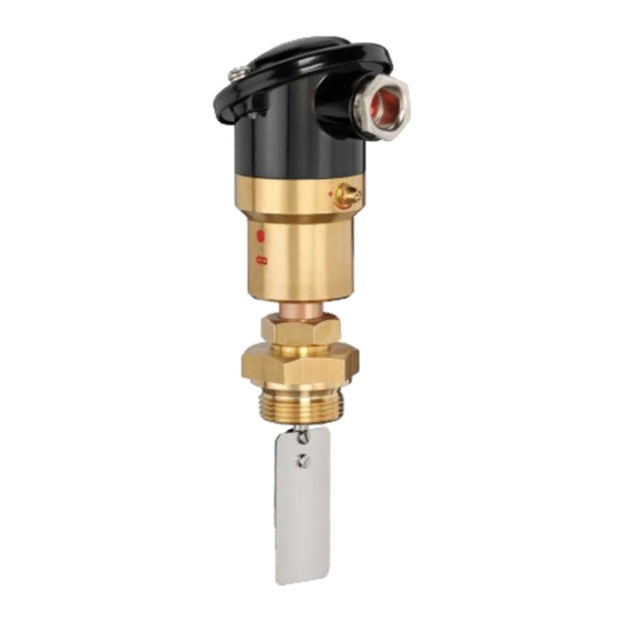
VH500 Aufbau Aufbau Gehäuseoberteil mit Deckel. Gehäuseunterteil mit Nippel, Klemmmutter und Flachdichtung / O-Ringen. Prozessanschluss in unterschiedlichen Aus- führungen: • Einschraubzapfen G1 oder • Einschraubzapfen M33x2. Prallfahnen. Kabelverschraubung. Mikroschalter. Schaltpunkteinstellung. Metallbalgsystem mit Bodenring und O-Ring. -
Page 6: Einbau
Für die richtige Anpassung an den Schaltpunktbereich müssen immer auch die kleineren Prallfahnen montiert werden. Montieren Sie die Prallfahnen von klein nach groß an der Fahnenstange. Ziehen Sie die Befestigung der Prallfahnen ausreichend fest an. - 6 - © SIKA • Ea2400_VH500 • 08/2021... -
Page 7: Montage
VH500 Einbau 3.3 Montage WICHTIG Reinigen Sie zuerst das Rohrleitungssystem bevor Sie den Strömungsschalter einbauen. Dadurch verhindern Sie, dass von der Montage stammende Verschmutzungen den Strömungsschalter blockieren. WICHTIG • Beachten Sie die Durchflussrichtung auf dem Gerät. • Beachten Sie die Einbaumaße ( S. 15). ... -
Page 8: Elektrischer Anschluss
Beschaltung des Mik- roschalters ( oben). Drehen Sie die Befestigungsschrauben der einzelnen Leitun- gen fest. Achten Sie auf den richtigen Sitz der Leitungen! Ziehen Sie die Mutter der Kabelverschraubung wieder fest. - 8 - © SIKA • Ea2400_VH500 • 08/2021... -
Page 9: Inbetriebnahme
VH500 Inbetriebnahme Deckel schließen WICHTIG Beim Schießen des Deckels können die Leitungen des Anschlusskabels und die Dichtung beschädigt werden. Achten Sie darauf, dass keine Leitungen eingeklemmt werden. Achten Sie auf den richtigen Sitz der Dichtung. Setzen Sie den Deckel mit Dichtung passend auf das Gehäuseoberteil. ... - Page 10 Ziehen Sie die Hutmutter fest, wenn der gewünschte Schaltpunkt eingestellt wurde. WICHTIG Der Gewindestift ist sowohl in -Richtung, als auch in -Richtung durch An- schläge begrenzt. Der Schaltpunkt kann nur innerhalb dieses Bereiches einge- stellt werden.. - 10 - © SIKA • Ea2400_VH500 • 08/2021...
-
Page 11: Wartung Und Rücksendung
Das Gerät besteht aus unterschiedlichen Werkstoffen. Es darf nicht zusammen mit Hausmüll entsorgt werden. Führen Sie den Strömungsschalter der lokalen Wiederverwertung zu oder schicken Sie den Strömungsschalter an Ihren Lieferanten bzw. SIKA zurück. * WEEE-Reg.-Nr.: DE 25976360 Technische Änderungen vorbehalten - 11 -... -
Page 12: Technische Daten
DNV GL, Baumusterzulassung Zertifikats-Nr.: TAA000011M (Rev.1) *1 Einbau in Nennweiten größer DN 50 möglich. Beachten Sie hierbei aber, dass die Werte der Schaltpunkte gegenüber den in dieser Betriebsanleitung angegebenen Werten abweichen. - 12 - © SIKA • Ea2400_VH500 • 08/2021... -
Page 13: Schaltpunkttabelle
VH500 Technische Daten 8.2 Schaltpunkttabelle Der einzustellende Bereich des Schaltpunktes des VH500 ist abhängig von der Nennweite und den verwendeten Prallfahnen. VH500N: Schaltpunktbereiche EIN/AUS [m • max. Durchfluss [m Nennweite DN 25 DN 32 Prallfahne Abmessung [mm] max. max. 25 x 30 1,10…1,25... -
Page 14: Werkstoffe
Klemmmutter Messing CW614N Flachdichtung HD 300 Einschraubzapfen Messing CW614N Metallbalgsystem Edelstahl 1.4571 Bodenring Messing CW614N O-Ring Fahnenstange Edelstahl 1.4571 Prallfahnen Edelstahl 1.4310 Zylinderschraube Edelstahl 1.4571 Sechskantmutter Edelstahl 1.4571 *1) Benetzte Bauteile. - 14 - © SIKA • Ea2400_VH500 • 08/2021... -
Page 15: Abmessungen
VH500 Technische Daten 8.4 Abmessungen VH500: ~135 ⎔ ~110 ⎔ ⎔ ⎔ M33x2 G1A 18,5 Technische Änderungen vorbehalten - 15 -... - Page 16 Offenders will be held liable for the payment of damages. All rights reserved in the event of the grant of a patent, utility model or de- sign. - 16 - © SIKA • Ea2400_VH500 • 08/2021...
-
Page 17: About This Operating Manual
Failure to do so may result in damage to property and the environment. If you have any problems or questions, please contact your supplier or contact us directly at: SIKA Dr. Siebert & Kühn GmbH & Co. KG Struthweg 7–9 34260 Kaufungen / Germany ... -
Page 18: Safety Instructions
Read through the operating manual carefully. Follow all instructions and notices to prevent injury or damage to property. Intended use SIKA flow switches may only be used for minimum or maximum monitoring of liquid flows. WARNING The flow switches of the series VH500 are no safety component in accordance with Directive 2006/42/EG (Machine Directive). -
Page 19: Construction
VH500 Construction Construction Upper housing part with cover. Lower housing part with adapter, clamping nut and O-rings. Process connection in different versions: • Screwed plug G1 or • Screwed plug M33x2. Baffle flags. Cable gland. ... -
Page 20: Installation Of The Flow Switch
Even the smaller baffle flags must always be installed for the correct adjustment to the setpoint range. Install the baffle flags from small to large on the flagpole. Tighten the mount of the baffle flags sufficiently. - 20 - © SIKA • Ea2400_VH500 • 08/2021... -
Page 21: Mounting
VH500 Installation of the flow switch 3.3 Mounting IMPORTANT Firstly, clean the pipe system before installing the flow switch. That prevents dirt originating from the assembly from blocking the flow switch. IMPORTANT • Pay attention to the flow direction on the device. •... -
Page 22: Electrical Connection
( above). Tighten the fixing screws of the individual wires. Ensure that the wires are connected properly! Tighten the nut of the cable gland again. - 22 - © SIKA • Ea2400_VH500 • 08/2021... -
Page 23: Commissioning
VH500 Commissioning Close the cover IMPORTANT When closing the cover, the leads of the connection cable and the gasket can be damaged. Make sure that the leads are not trapped. Pay attention to the correct seating of the gasket. ... - Page 24 When the desired setpoint has been set, tighten the cap nut. IMPORTANT The grub screw is limited by stops in direction as well as in direction. The setpoint can only be set within this range. - 24 - © SIKA • Ea2400_VH500 • 08/2021...
-
Page 25: Maintenance And Return Shipment
The device consists of various different materials. It must not be disposed of with household waste. Take the flow switch to your local recycling plant send the flow switch back to your supplier or to SIKA. * WEEE reg. no.: DE 25976360 Technical changes reserved... -
Page 26: Technical Data
*1 Installation in nominal sizes larger than DN 50 possible. Please note, however, that the values of the setpoints differ from the values of the setpoints given in this operating manual. - 26 - © SIKA • Ea2400_VH500 • 08/2021... -
Page 27: Setpoint Tables
VH500 Technical data 8.2 Setpoint tables The range of the setpoint of the VH500 depends on the nominal size and the baffle flags used. VH500N: Setpoint ranges ON/OFF [m • max. flow rate [m Nominal size DN 25 DN 32... -
Page 28: Materials
Stainless steel 1.4571 Bottom ring Brass CW614N O-ring FVMQ Flagpole Stainless steel 1.4571 Baffle flag Stainless steel 1.4571 Cylinder screw Stainless steel 1.4571 Hexagon nut Stainless steel 1.4571 *1) Wetted Components. - 28 - © SIKA • Ea2400_VH500 • 08/2021... -
Page 29: Dimensions
VH500 Technical data 8.4 Dimensions VH500: ~135 ⎔ ~110 ⎔ ⎔ ⎔ M33x2 G1A 18.5 Technical changes reserved - 29 -... - Page 30 VH500 - 30 - © SIKA • Ea2400_VH500 • 08/2021...
- Page 31 VH500 Technical changes reserved - 31 -...
- Page 32 SIKA Dr. Siebert & Kühn GmbH & Co. KG Struthweg 7–9 34260 Kaufungen / Germany +49 5605 803-0 +49 5605 803-555 info@sika.net www.sika.net © SIKA • Ea2400_VH500 • 08/2021...
Need help?
Do you have a question about the VH500N and is the answer not in the manual?
Questions and answers