Table of Contents
Advertisement
Quick Links
Advertisement
Table of Contents
Troubleshooting

Related Manuals for Miller Swingarc DS-74S/D


Summary of Contents for Miller Swingarc DS-74S/D
- Page 1 OM-1500-13 207 494L 2009−09 Processes MIG (GMAW) Welding Flux Cored (FCAW) Welding (Gas-and Self-Shielding) Submerged (SAW) Welding Description Wire Feeder (Use with CV Power Sources) DS-74S/D Swingarc ™ DS-74S/D8, DS-74S/D12, and DS-74S/D16 File: MIG (GMAW) Visit our website at www.MillerWelds.com...
- Page 2 We know you don’t have time to do it any other way. That’s why when Niels Miller first started building arc welders in 1929, he made sure his products offered long-lasting value and superior quality.
-
Page 3: Table Of Contents
TABLE OF CONTENTS SECTION 1 − SAFETY PRECAUTIONS - READ BEFORE USING ........1-1. -
Page 5: Section 1 − Safety Precautions - Read Before Using
SECTION 1 − SAFETY PRECAUTIONS - READ BEFORE USING som _2009−08 Protect yourself and others from injury — read and follow these precautions. 1-1. Symbol Usage DANGER! − Indicates a hazardous situation which, if Indicates special instructions. not avoided, will result in death or serious injury. The possible hazards are shown in the adjoining symbols or explained in the text. - Page 6 D Remove stick electrode from holder or cut off welding wire at FUMES AND GASES can be hazardous. contact tip when not in use. D Wear oil-free protective garments such as leather gloves, heavy Welding produces fumes and gases. Breathing shirt, cuffless trousers, high shoes, and a cap.
-
Page 7: Additional Symbols For Installation, Operation, And Maintenance
1-3. Additional Symbols For Installation, Operation, And Maintenance FIRE OR EXPLOSION hazard. MOVING PARTS can injure. D Do not install or place unit on, over, or near D Keep away from moving parts such as fans. combustible surfaces. D Keep all doors, panels, covers, and guards D Do not install unit near flammables. -
Page 8: California Proposition 65 Warnings
1-4. California Proposition 65 Warnings For Gasoline Engines: Welding or cutting equipment produces fumes or gases which contain chemicals known to the State of California to Engine exhaust contains chemicals known to the State of cause birth defects and, in some cases, cancer. (California California to cause cancer, birth defects, or other reproduc- Health &... -
Page 9: Section 2 − Consignes De Sécurité − Lire Avant Utilisation
SECTION 2 − CONSIGNES DE SÉCURITÉ − LIRE AVANT UTILISATION fre_som_2009−08 Se protéger et protéger les autres contre le risque de blessure — lire et respecter ces consignes. 2-1. Symboles utilisés DANGER! − Indique une situation dangereuse qui si on Indique des instructions spécifiques. - Page 10 Il reste une TENSION DC NON NÉGLIGEABLE dans D Porter des vêtements confectionnés avec des matières résistan- tes et ignifuges (cuir, coton lourd ou laine) et des bottes de les sources de soudage onduleur UNE FOIS protection. l’alimentation coupée. LE SOUDAGE peut provoquer un D Arrêter les convertisseurs, débrancher le courant électrique et incendie ou une explosion.
-
Page 11: Dangers Supplémentaires En Relation Avec L'installation, Le Fonctionnement Et La Maintenance
ACCUMULATIONS LES BOUTEILLES peuvent exploser risquent de provoquer des blessures si elles sont endommagées. ou même la mort. Des bouteilles de gaz protecteur contiennent du gaz sous haute pression. Si une bouteille est endom- D Fermer l’alimentation du gaz protecteur en cas magée, elle peut exploser. -
Page 12: Proposition Californienne 65 Avertissements
Les PIÈCES MOBILES peuvent RAYONNEMENT HAUTE causer des blessures. FRÉQUENCE (H.F.) risque provoquer des interférences. D Ne pas s’approcher des organes mobiles. D Ne pas s’approcher des points de coincement D Le rayonnement haute fréquence (H.F.) peut tels que des rouleaux de commande. provoquer des interférences avec les équi- pements de radio−navigation et de com- munication, les services de sécurité... -
Page 13: Principales Normes De Sécurité
2-5. Principales normes de sécurité Safety in Welding, Cutting, and Allied Processes, ANSI Standard Z49.1, 25 West 43rd Street, New York, NY 10036 (téléphone : 212-642-4900, de Global Engineering Documents (téléphone : 1-877-413-5184, site site Internet : www.ansi.org). Internet : www.global.ihs.com). Standard for Fire Prevention During Welding, Cutting, and Other Hot Safe Practices for the Preparation of Containers and Piping for Welding Work, NFPA Standard 51B, de National Fire Protection Association,... - Page 14 OM-1500-13 Page 10...
-
Page 15: Section 3 − Introduction
SECTION 3 − INTRODUCTION 3-1. Specifications Type of Input Welding Power Wire Feed Speed Wire Diameter Welding Circuit Ship Weight Power Source Type Range Range Rating 8 ft (2.4 m): Standard: 50 To 780 ipm 400 lb (181 kg) .023 To 1/8 in. (0.6 100 Volts, (1.3 To 19.8 mpm) 24 Volts AC... -
Page 16: Installing Control Box And Adjusting Tilt
4-2. Installing Control Box And Adjusting Tilt Weld Control Bracket Screw Bracket and screws are installed onto bottom of control at factory. Swivel Loosen screws. Place control on swivel and slide forward. Tighten screws. Tilt Bracket Rear Pivot Screw Front Screw Loosen rear pivot screw. -
Page 17: Installing Wire Guide Extension
4-4. Installing Wire Guide Extension Wire Guide Fitting Bolt Monocoil Liner Wire Guide Extension Tighten bolt to secure liner in wire guide fitting. Do not overtighten bolt and crush liner. Repeat procedure for opposite side. Tools Needed: 3/8 in. ST-152 383 OM-1500-13 Page 13... -
Page 18: Equipment Connection Diagram
4-5. Equipment Connection Diagram Welding Power Source Remote 14 Connection Negative (−) Weld Output Cable Positive (+) Weld Output Cable Workpiece Weld Control Boom Swivel 10 Pipe Post And Base 11 Gas Hose 12 Gas Supply and Regulator (Customer Supplied) Shielding gas pressure not to exceed 100 PSI (689 kPa). -
Page 19: Control Box Connections
4-6. Control Box Connections Interconnecting Cables Interconnecting Cable Receptacles 14-Pin Cord Ref. 803 187 4-7. 14-Pin Plug Information Pin* Pin Information 24 volts AC with respect to socket G. Contact closure to A completes 24 volts AC contactor control circuit. Circuit common for 24 volts AC circuit. -
Page 20: Removing Safety Collar And Adjusting Boom
4-8. Removing Safety Collar And Adjusting Boom Locking Knob Tighten knob to prevent boom movement. Loosen knob to allow boom movement. Change knob po- sition to limit upward movement. Pull boom down slightly and re- move safety collar. Boom should balance in any position from hori- zontal to 60 degrees above hori- zontal. -
Page 21: Installing And Threading Welding Wire
4-10. Installing And Threading Welding Wire Tools Needed: 3/8, 15/16 in. 3/16, 5/64 in. Install wire spool. Ad- just tension nut so wire is taut when wire feed stops. Pressure Adjust Pressure Indicator Scale Install wire guide. Pressure Adjust Drive Rolls Install drive rolls. -
Page 22: Setting Internal Dip Switches
4-11. Setting Internal DIP Switches Remove wrapper. Left Side Motor DIP Switch S1 On Motor Control Board Board PC1 PC101 w Setting Current Detect Override (S1-1) Current detect override is used to disable run-in when a welding pow- Right Side Motor er source is used that doesn’t pro- Control Board PC1 vide current feedback through the... -
Page 23: Optional Equipment Dip Switch Settings
4-12. Optional Equipment DIP Switch Settings Remove wrapper. Digital Meter Board PC60 Meter Board Switch S2 Install wrapper when finished. Digital Meter Functions Standard Standard High Speed High Speed Motor Motor Motor Motor Inches/Minute Meters/Minute Inches/Minute Meters/Minute PC60 Tools Needed: 1/4 in. -
Page 24: Section 5 − Operation
SECTION 5 − OPERATION 5-1. Power Switch Power Switch Ref. 803 183 5-2. Left/Right Select Switch Left/Right Select Switch Pressing the Left/Right Select switch allows the operator to choose which side of the unit’s con- trols will operate. Ref. 803 184 5-3. -
Page 25: Trigger Hold Switch
5-4. Trigger Hold Switch Trigger Hold Switches Trigger hold allows the operator to weld without holding the gun trigger. • To use the trigger hold function, place the trigger hold switch in the On position. • The operator must hold the trig- ger for a minimum of 2 seconds, but not longer than 6 seconds be- fore releasing it. -
Page 26: Section 6 − Maintenance & Troubleshooting
SECTION 6 − MAINTENANCE & TROUBLESHOOTING 6-1. Routine Maintenance Disconnect power before maintaining. 3 Months Clean and Repair or tighten Replace replace weld unreadable cracked terminals. labels. weld cable. Replace Check Check gas Check gun cracked 14-pin cord. hose and cable. -
Page 27: Diagnostics
6-2. Diagnostics LED3 On Right Side Motor Control Board PC1 LED3 On Left Side Motor Control Board PC101 LED3 On Dual Board PC70 805 407-A Display On LED3 Sequence Indicated Error Optional Meter HELP 11 1 Blink Communication Error Left Side Motor Control Board PC101 HELP 12 2 Blinks... -
Page 28: Troubleshooting
6-3. Troubleshooting Disconnect power before troubleshooting. Trouble Remedy Wire feeds, shielding gas flows, but Check cable connections. Check cables for continuity, and repair or replace cables if necessary electrode wire is not energized. (see Section 4-5). Wire feeder is on, display does not light Check and reset circuit breaker at welding power source. - Page 29 Notes OM-1500-13 Page 25...
-
Page 30: Section 7 − Electrical Diagram
SECTION 7 − ELECTRICAL DIAGRAM Figure 7-1. Circuit Diagram OM-1500-13 Page 26... - Page 31 204 716-B OM-1500-13 Page 27...
-
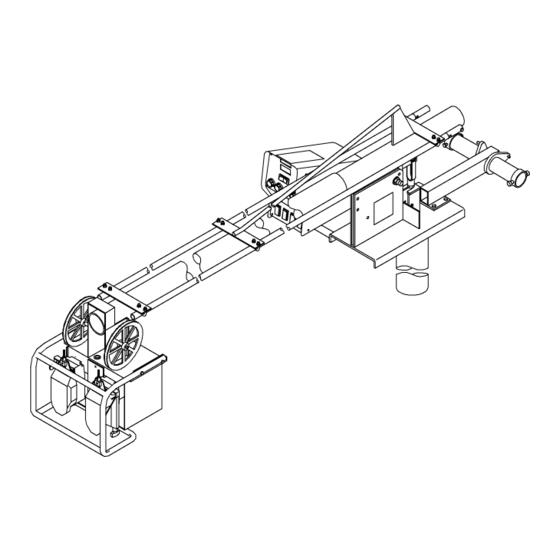
Page 32: Section 8 − Parts List
SECTION 8 − PARTS LIST Hardware is common and not available unless listed. 803 189-C Figure 8-1. Main Assembly OM-1500-13 Page 28... - Page 33 Quantity Model Item Dia. Part Mkgs. Description Figure 8-1. Main Assembly ....See Note . . . Control Box, (Fig 8-2) ......
- Page 34 Quantity Model Item Dia. Part Mkgs. Description Figure 8-1. Main Assembly (Continued) ....♦201 777 . . . Drive Assy, Wire L Vert 4 Roll Hi−Speed W/Cl&Tach .
- Page 35 ....206 513 Nameplate, Miller D-74S Upper ......
- Page 36 Hardware is common and not available unless listed. ST-142 306-H Figure 8-3. Boom Assembly OM-1500-13 Page 32...
- Page 37 Quantity Model Item Part Description Figure 8-3. Boom Assembly (Fig 8-1 Item 14) ... . 010 313 Pin, Cotter Hair .072 X 1.437 ......
- Page 38 Hardware is common and not available unless listed. See Table 8-1 For Drive Roll & Wire Guide Kits 802 977-B Figure 8-4. Drive Assembly, Wire Quantity Model Item Dia. Part Mkgs. Description DS-74S DS-74D Figure 8-4. Drive Assembly, Wire (Figure 8-1 Item 26) .
- Page 39 Quantity Model Item Dia. Part Mkgs. Description DS-12 DS-16 Figure 8-4. Drive Assembly, Wire (continued) ..... 184 136 ..Kit, Brush Holder .
- Page 40 Hardware is common and not available unless listed. ST-081 760-C Figure 8-5. Support, Hub & Reel Item Part Description Quantity Figure 8-5. Support, Hub & Reel (Fig 8-1 Item 11) ..058 427 Ring, Retaining Spool .
- Page 41 Table 8-1. Drive Roll And Wire Guide Kits OM-1500-13 Page 37...
- Page 42 Notes...
- Page 43 Effective January 1, 2009 (Equipment with a serial number preface of LK or newer) This limited warranty supersedes all previous Miller warranties and is exclusive with no other Warranty Questions? guarantees or warranties expressed or implied. LIMITED WARRANTY − Subject to the terms and conditions...
- Page 44 Contact the Delivering Carrier to: File a claim for loss or damage during shipment. For assistance in filing or settling claims, contact your distributor and/or equipment manufacturer’s Transportation Department. © ORIGINAL INSTRUCTIONS − PRINTED IN USA 2009 Miller Electric Mfg. Co. 2009−01...
Need help?
Do you have a question about the Swingarc DS-74S/D and is the answer not in the manual?
Questions and answers