Table of Contents
Advertisement
Advertisement
Table of Contents
Troubleshooting

Subscribe to Our Youtube Channel
Related Manuals for Miller Maxstar 210


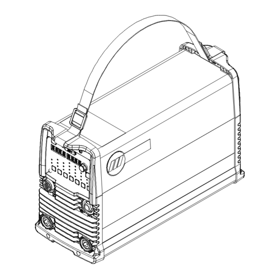
Summary of Contents for Miller Maxstar 210
- Page 1 OM-270536T 2023-02 Processes TIG (GTAW) Welding Stick (SMAW) Welding Description 120-480 Volt Models w/Autoline® Arc Welding Power Source Dynasty ® Maxstar ® CE And Non-CE Models OWNER’S MANUAL For product information, Owner’s Manual translations, and more, visit www.MillerWelds.com...
- Page 2 We know you don’t have time to do it any other way. That’s why when Niels Miller first started building arc welders in 1929, he made sure his products offered long-lasting value and superior quality.
-
Page 3: Table Of Contents
SECTION 9 – MAXSTAR 210 STR OPERATION........ - Page 4 Accessing Tech Menu For Dynasty/Maxstar 210 Models ........
- Page 5 DECLARATION OF CONFORMITY for European Community (CE marked) products. MILLER Electric Mfg. LLC, 1635 Spencer Street, Appleton, WI 54914 U.S.A. declares that the product(s) identified in this declaration conform to the essential requirements and provisions of the stated Council Directive(s), Commission Regulation(s) and Standard(s).
- Page 6 DECLARATION OF CONFORMITY For United Kingdom (UKCA marked) products. MILLER Electric Mfg. LLC, 1635 West Spencer Street, Appleton, WI 54914 U.S.A. declares that the product(s) identified in this declaration conform to the essential requirements and provisions of the stated Regulation(s) and Standard(s).
- Page 7 EMF DATA SHEET FOR ARC WELDING POWER SOURCE Product/Apparatus Identification Product Stock Number MAXSTAR 210 DX (AUTO-LINE 120-480 V) (CE) 907684001 Compliance Information Summary Applicable regulation Directive 2014/35/EU Reference limits Directive 2013/35/EU, Recommendation 1999/519/EC Applicable standards IEC 62822-1:2016, IEC 62822-2:2016...
-
Page 9: Section 1 - Safety Precautions - Read Before Using
SECTION 1 – SAFETY PRECAUTIONS – READ BEFORE USING Protect yourself and others from injury—read, follow, and save these important safety precautions and operating instructions. 1-1. Symbol Usage DANGER! – Indicates a hazardous situation which, if not avoided, will result in death or serious injury. The possible hazards are shown in the adjoining symbols or explained in the text. - Page 10 HOT PARTS can burn. WELDING can cause fire or explosion. � Do not touch hot parts bare handed. � Allow cooling period before working on equipment. Welding on closed containers, such as tanks, drums, or pipes, can cause them to blow up. �...
-
Page 11: Additional Hazards For Installation, Operation, And Maintenance
� Never weld on a pressurized cylinder—explosion will result. CYLINDERS can explode if � Use only correct compressed gas cylinders, regulators, hoses, damaged. and fittings designed for the specific application; maintain them Compressed gas cylinders contain gas under high and associated parts in good condition. pressure. -
Page 12: California Proposition 65 Warnings
� To reduce possible interference, keep weld cables as short as ARC WELDING can cause possible, close together, and down low, such as on the floor. interference. � Locate welding operation 100 meters from any sensitive electronic equipment. � Electromagnetic energy can interfere with sensitive electronic equipment such as microprocessors, �... -
Page 13: Section 2 - Consignes De Sécurité - Lire Avant Utilisation
SECTION 2 – CONSIGNES DE SÉCURITÉ - LIRE AVANT UTILISATION Pour écarter les risques de blessure pour vous-même et pour autrui — lire, appliquer et ranger en lieu sûr ces consignes relatives aux précautions de sécurité et au mode opératoire. 2-1. - Page 14 � S’assurer que tous les panneaux et couvercles sont correctement LES ACCUMULATIONS DE GAZ en place. risquent de provoquer des blessures � Fixer le câble de retour de façon à obtenir un bon contact métal- ou même la mort. métal avec la pièce à souder ou la table de travail, le plus près possible de la soudure.
-
Page 15: Symboles De Dangers Supplémentaires En Relation Avec L'installation, Le Fonctionnement Et La Maintenance
� Brancher le câble de masse sur la pièce le plus près possible de � Les porteurs d’implants médicaux doivent consulter leur médecin la zone de soudage pour éviter le transport du courant sur une lon- et le fabricant du dispositif avant de s’approcher de la zone où se gue distance par des chemins inconnus éventuels en provoquant déroule du soudage à... -
Page 16: Proposition Californienne 65 Avertissements
� Affûter l'électrode au tungstène uniquement à la meuleuse dotée LIRE LES INSTRUCTIONS. de protecteurs. Cette manœuvre est à exécuter dans un endroit sûr lorsque l'on porte l'équipement homologué de protection du vi- � Lire et appliquer les instructions sur les étiquettes sage, des mains et du corps. -
Page 17: Informations Relatives Aux Cem
Safety in Welding, Cutting, and Allied Processes, CSA Standard Subpart N, Part 1910 Subpart Q, and Part 1926, Subpart J. Website: W117.2 from Canadian Standards Association. Website: www. csa- www.osha.gov. group.org. OSHA Important Note Regarding the ACGIH TLV, Policy Statement on the Uses of TLVs and BEIs. -
Page 18: Section 3 - Definitions
Reuse or recycle Waste Electrical and Electronic Equipment (WEEE) by disposing at a designated collection Some symbols are found only on CE products. Warning! Watch Out! There are possible hazards as shown by the symbols. Some symbols are found only on CE products. facility. - Page 19 Cutting sparks can cause fires. Have a fire extinguisher nearby, and have a watchperson ready to use it. Do not grip material near cutting path. � Complete Parts List is available at www.MillerWelds.com Safe1 Safe Do not fuel a hot engine. Do not fuel a hot engine.
-
Page 20: Miscellaneous Symbols And Definitions
Connect Green Or Green/Yellow grounding conductor to ground terminal first. Connect input conductors (L1, L2, L3) to line terminals. � Complete Parts List is available at www.MillerWelds.com Safe36 2012 05 Safe67 2012 06 Move jumper links as shown on inside label to match input voltage at Wear hat and safety glasses. - Page 21 � Complete Parts List is available at www.MillerWelds.com Arc Striking without Conventional Load Contact (HF And Panel-Local Voltage Impulse) Shielded Metal Arc Primary Voltage Final Slope Welding (SMAW) A complete Parts A complete Parts L Degree of Protective Earth Final Amperage Protection 1-2.
-
Page 22: Section 4 - Specifications
Information About Default Weld Parameters And Settings NOTICE – Each welding application is unique. Although certain Miller Electric products are designed to determine and default to certain typical welding parameters and settings based upon specific and relatively limited application variables input by the end user, such default settings are for reference purposes only;... - Page 23 � Complete Parts List is available at www.MillerWelds.com Current Draw (A) At Rated Output Ratings Input Power Input Voltages (V) Process Phase Current Voltage Duty 120V 208V 240V 400V 480V Cycle Power Draw (W) — — Idle OCV 77.5 — —...
-
Page 24: Dimensions, Weights, And Mounting Options
SECTION 2 INSTALLATION A. Welding Power Source � 2-1. Dimensions, Weights, And Mounting Options Complete Parts List is available at www.MillerWelds.com 4-5. Dimensions, Weights, And Mounting Options A. Welding Power Source A. Welding Power Source Dimensions 13-5/8 in. (346 mm) 8-5/8 in. - Page 25 � Complete Parts List is available at www.MillerWelds.com C. Mounting Options Dimensions 15-7/16 in. (392 mm) A complete Parts List is available at www.MillerWelds.com 9-19/32 in. (244 mm) Center-To-Center 5/16 in. (8 mm) 17-15/32 in. (444 mm) 3-3/4 in. (95 mm) 13/64 in.
-
Page 26: Duty Cycle And Overheating
� Complete Parts List is available at www.MillerWelds.com 4-6. Duty Cycle And Overheating Duty Cycle is percentage of 10 minutes that unit weld rated load without overheating. If unit overheats, output stops, a Help mes- sage is displayed (see Section 12-4), and cooling fan runs. -
Page 27: Environmental Specifications
� Complete Parts List is available at www.MillerWelds.com 4-8. Environmental Specifications A. IP Rating IP Rating IP23 This equipment is designed for outdoor use. B. Temperature Specifications Operating Temperature Range* Storage/Transportation Temperature Range 14 to 104°F (-10 to 40°C) -4 to 131°F (-20 to 55°C) *Output is derated at temperatures above 104°F (40°C). - Page 28 E. EU Ecodesign Information Minimum Power Source Maximum Idle State Model Input Efficiency Power Consumption Warning! Watch Out! There are possible hazards as shown by the symbols. Maxstar 210 400V Three Phase 85.2% 15.55 W Maxstar 210 230V Three Phase 82.0% 14.90 W Safe1 2012 Do not discard product (where applicable) with general waste.
-
Page 29: Section 5 - Installation
� Complete Parts List is available at www.MillerWelds.com SECTION 5 – INSTALLATION 18 in. (460 mm) 5-1. Selecting A Location Do not move or operate unit where Movement it could tip. Special installation may be re- quired where gasoline or volatile liquids are present - see NEC Ar- ticle 511 or CEC Section 20. -
Page 30: Selecting Cable Sizes
� Complete Parts List is available at www.MillerWelds.com 5-2. Selecting Cable Sizes NOTICE – The Total Cable Length in Weld Circuit (see table below) is the combined length of both weld cables. For example, if the power source is 100 ft (30 m) from the workpiece, the total cable length in the weld circuit is 200 ft (2 cables x 100 ft). Use the 200 ft (60 m) column to determine cable size. -
Page 31: Connections
� Complete Parts List is available at www.MillerWelds.com 5-3. Connections Rear Panel Dynasty Front Panel Turn off power before connecting Dynasty Front Panel to weld output terminals. Do not use worn, damaged, under- sized, or repaired cables. Dynasty Connections 1 Remote Control Receptacle (see Section 5-9) 2 Gas Out To Torch Connection Rear Panel... -
Page 32: Cooler Connections
� Complete Parts List is available at www.MillerWelds.com 5-4. Cooler Connections � Cart cooler optional equipment. 1 Coolmate 1.3 Power Receptacle 2 Cooler Power Cord Provides 115 VAC to power cooler. 3 Electrode Weld Output Terminal ( – Weld Output Terminal on Maxstar Models) Connect TIG torch to electrode weld output terminal. -
Page 33: Electrical Service Guide (Dynasty)
� Complete Parts List is available at www.MillerWelds.com 5-5. Electrical Service Guide (Dynasty) A. Electrical Service Guide For Three-Phase Operation Failure to follow these electrical service guide recommendations could create an electric shock or fire hazard. These recommen- dations are for an individual branch circuit sized for the rated output and duty cycle of one welding power source. In individual branch circuit installations, the National Electrical Code (NEC) allows the receptacle or conductor rating to be less than the rating of the circuit protection device. -
Page 34: Electrical Service Guide (Maxstar)
� Complete Parts List is available at www.MillerWelds.com 5-6. Electrical Service Guide (Maxstar) A. Electrical Service Guide For Three-Phase Operation Failure to follow these electrical service guide recommendations could create an electric shock or fire hazard. These recommen- dations are for an individual branch circuit sized for the rated output and duty cycle of one welding power source. In individual branch circuit installations, the National Electrical Code (NEC) allows the receptacle or conductor rating to be less than the rating of the circuit protection device. -
Page 35: Connecting 3-Phase Input Power
� Complete Parts List is available at www.MillerWelds.com 5-7. Connecting 3-Phase Input Power Installation must meet all National and Local Codes—have only quali- fied persons make this installation. Disconnect and lockout/tagout in- put power before connecting input conductors from unit. Follow es- tablished procedures regarding... -
Page 36: Connecting 1-Phase Input Power
A complete Parts List is available at www.MillerWelds.com � Complete Parts List is available at www.MillerWelds.com 2-5. Connecting Single-Phase Input Power 5-8. Connecting 1-Phase Input Power Installation must meet all National and Local Codes—have only quali- fied persons make this installation. Disconnect and lockout/tagout in- put power before connecting input conductors from unit. -
Page 37: Remote 14 Receptacle Information
� Complete Parts List is available at www.MillerWelds.com 5-9. Remote 14 Receptacle Information Remote 14 Socket Socket Information Contactor control +15 volts DC, referenced to G. 15 Volts DC Output Contact closure to A completes 15 volts DC con- Contactor tactor control circuit and enables output. -
Page 38: Software Updates
The SD logo is a registered trademark of SD-3C LLC. How To Download Software Updates 805 497-A 1 In a web browser, go to https://www.miller- welds.com/support/software/tig-software 2 Click Installation Instructions (PDF) and follow the instructions. B. Installing Software Updates A. Software Installation... -
Page 39: Section 6 - Dynasty 210 Operation
A complete Parts List is available at www.MillerWelds.com � Complete Parts List is available at www.MillerWelds.com SECTION 3 DYNASTY 210 OPERATION SECTION 6 – DYNASTY 210 OPERATION 3-1. Dynasty 210 Controls 6-1. Dynasty 210 Controls 247222-D 4 Voltmeter Blue indicator illuminates when output is on. 1 Standby Button Displays actual rectified average voltage 8 Process Selector Control... -
Page 40: Accessing Control Panel Menu: Ac Tig
e at www.MillerWelds.com � Complete Parts List is available at www.MillerWelds.com A complete Parts List is available at www.MillerWelds.com 6-2. Accessing Control Panel Menu: AC TIG 3-2. Accessing Control Panel Menu: AC TIG 1 Menu Button Press Menu button to cycle through parame- ters that can be set. -
Page 41: Accessing Control Panel Menu: Dc Tig
� Complete Parts List is available at www.MillerWelds.com 6-3. Accessing Control Panel Menu: DC TIG 1 Menu Button Press Menu button to cycle through parame- ters that can be set. 2 Parameter Display 3 Setting Display 4 Amperage Adjustment Control Rotate Amperage Adjustment control to ad- just parameter setting. -
Page 42: Accessing Control Panel Menu: Ac And Dc Stick
� Complete Parts List is available at www.MillerWelds.com 6-4. Accessing Control Panel Menu: AC And DC Stick 1 Menu Button Press Menu button to cycle through parame- ters that can be set. 2 Parameter Display 3 Setting Display 4 Amperage Adjustment Control Rotate Amperage Adjustment control to ad- just parameter setting. -
Page 43: Accessing User Setup Menu: Ac And Dc Tig
� Complete Parts List is available at www.MillerWelds.com A complete Parts List is available at www.MillerWelds.com 6-5. Accessing User Setup Menu: AC And DC TIG 3-5. Accessing User Setup Menu: AC And DC TIG 1 Menu Button Press and hold Menu button for approxi- mately 2 seconds to access machine User Setup menu. -
Page 44: Accessing User Setup Menu: Ac And Dc Stick
� Complete Parts List is available at www.MillerWelds.com 6-6. Accessing User Setup Menu: AC And DC Stick A complete Parts List is available at www.MillerWelds.com 3-6. Accessing User Setup Menu: AC And DC Stick 1 Menu Button Press and hold Menu button for approxi- mately 2 seconds to access User Setup menu. -
Page 45: Section 7 - Dynasty 210 Dx Operation
SECTION 4 DYNASTY 210 DX OPERATION � Complete Parts List is available at www.MillerWelds.com SECTION 7 – DYNASTY 210 DX OPERATION 4-1. Dynasty 210 DX Controls 7-1. Dynasty 210 DX Controls 247220-D Use amperage adjustment control in con- terminals. It is also used to display parame- �... -
Page 46: Accessing Control Panel Menu
4-2. Accessing Control Panel Menu � Complete Parts List is available at www.MillerWelds.com 7-2. Accessing Control Panel Menu 1 Amperage Button 2 Parameter Display A complete Parts List is available at www.MillerWelds.com 3 Setting Display 4 Amperage Adjustment Control 4-2. Accessing Control Panel Menu Rotate amperage adjustment control to ad- just parameter setting. - Page 47 � Complete Parts List is available at www.MillerWelds.com Output (Trigger Mode Selection) 247220-D � See Section 11 for additional trigger function options. Parameter/Setting Description Display [RMT] [STD] Typical setting for a remote foot or hand control. RMT STD requires a maintained contact closure to enable weld output.
- Page 48 � Complete Parts List is available at www.MillerWelds.com AC Waveshape Control Parameter/Setting Description Display [BAL] [75%] Balance Control (%EN) TIG Only: Controls oxide cleaning. Increasing the setting reduces cleaning. Range is BALL, 50 - 99%. Stick is fixed at 50%. "BALL" sets the Balance to 30%. This is to allow the op- erator to form a ball on the tip of the tungsten.
-
Page 49: Accessing User Setup Menu
A complete Parts List is available at www.MillerWelds.com � Complete Parts List is available at www.MillerWelds.com 4-3. Accessing User Setup Menu 7-3. Accessing User Setup Menu 1 Amperage Button 2 Gas/Dig Button 3 Parameter Display 4 Setting Display 5 Amperage Adjustment Control To access the User Setup menu, press and USER MENU... -
Page 50: Ac Independent Expansion
SECTION 5 MAXSTAR 210 OPERATION Press AC Waveshape button until desired function is selected. � Both Balance and AC Frequency LEDs light when either EN or EP Amperage is selected. 5-1. Maxstar 210 Controls Parameter/Setting Display Description Example [EN] [150A] EN Amperage: Use with AC TIG only to select electrode negative amperage value. -
Page 51: Section 8 - Maxstar 210 Operation
� Complete Parts List is available at www.MillerWelds.com SECTION 5 MAXSTAR 210 OPERATION SECTION 8 – MAXSTAR 210 OPERATION 5-1. Maxstar 210 Controls 8-1. Maxstar 210 Controls LIFT ARC HF START Schedule 2 Schedule 1 247218-C OM-270536 Page 2 This port is used to add features to the ma- 7 Output ON Indicator �... -
Page 52: Accessing Control Panel Menu: Dc Tig Hf And Lift-Arc
� Complete Parts List is available at www.MillerWelds.com A complete Parts List is available at www.MillerWelds.com 8-2. Accessing Control Panel Menu: DC TIG HF And Lift-Arc 5-2. Accessing Control Panel Menu: DC TIG HF And Lift Arc 1 Menu Button Press Menu button to cycle through parame- ters that can be set. -
Page 53: Accessing Control Panel Menu: Dc Stick
� Complete Parts List is available at www.MillerWelds.com A complete Parts List is available at www.MillerWelds.com 8-3. Accessing Control Panel Menu: DC Stick 5-3. Accessing Control Panel Menu: DC Stick 1 Menu Button Press Menu button to cycle through parame- ters that can be set. -
Page 54: Accessing User Setup Menu: Dc Tig And Lift-Arc
� Complete Parts List is available at www.MillerWelds.com 8-4. Accessing User Setup Menu: DC TIG And Lift-Arc A complete Parts List is available at www.MillerWelds.com 5-4. Accessing User Setup Menu: DC TIG And Lift-Arc 1 Menu Button Press and hold Menu button for approxi- mately 2 seconds to access User Setup menu. -
Page 55: Accessing User Setup Menu: Ac And Dc Stick
� Complete Parts List is available at www.MillerWelds.com A complete Parts List is available at www.MillerWelds.com 8-5. Accessing User Setup Menu: AC And DC Stick 5-5. Accessing User Setup Menu: DC Stick 1 Menu Button Press and hold Menu button for approxi- mately 2 seconds to access User Setup menu. -
Page 56: Section 9 - Maxstar 210 Str Operation
� Complete Parts List is available at www.MillerWelds.com A complete Parts List is available at www.MillerWelds.com SECTION 9 – MAXSTAR 210 STR OPERATION SECTION 6 MAXSTAR 210 STR OPERATION 9-1. Maxstar 210 STR Controls 6-1. Maxstar 210 STR Controls Schedule 1... -
Page 57: Accessing Control Panel Menu: Dc Tig Lift-Arc
� Complete Parts List is available at www.MillerWelds.com A complete Parts List is available at www.MillerWelds.com 9-2. Accessing Control Panel Menu: DC TIG Lift-Arc 6-2. Accessing Control Panel Menu: DC TIG Lift Arc 1 Menu Button Press Menu button to cycle through parame- ters that can be set. -
Page 58: Accessing User Setup Menu: Dc Tig Lift-Arc And Dc Stick
� Complete Parts List is available at www.MillerWelds.com Arc Force Control* Parameter/Setting Display Description [DIG] [30%] Controls the amount of additional amperage at low voltage (short arc length) conditions. Adjust the force of the arc for different joint configurations and electrodes. Range is OFF-100%. Features PRO-SET val- ues for 6010 and 7018 electrodes. -
Page 59: Section 10 - Maxstar 210 Dx Operation
A complete Parts List is available at www.MillerWelds.com � Complete Parts List is available at www.MillerWelds.com SECTION 7 MAXSTAR 210 DX OPERATION SECTION 10 – MAXSTAR 210 DX OPERATION 7-1. Maxstar 210 DX Controls 10-1. Maxstar 210 DX Controls 247216-A... -
Page 60: Accessing Control Panel Menu
7-2. Accessing Control Panel Menu 4-2. Accessing Control Panel Menu � Complete Parts List is available at www.MillerWelds.com 10-2. Accessing Control Panel Menu 1. Amperage Button 2. Parameter Display 3. Setting Display 4. Encoder Rotate Encoder to adjust paramet- er setting. The Amperage Control controls the 1 Amperage Button welding amperage output, and lim-... - Page 61 � Complete Parts List is available at www.MillerWelds.com Pulse Control Pulsing is available in the TIG process. Controls can be adjusted while welding. Reduces heat input to minimize distortion and increase travel speed. Range is 0.1 to 500 pulses per second. Press button to enable pulser.
-
Page 62: Accessing User Setup Menu
A complete Parts List is available at www.MillerWelds.com � Complete Parts List is available at www.MillerWelds.com 7-3. Accessing User Setup Menu 10-3. Accessing User Setup Menu 1 Amperage Button 2 Gas/Dig Button 3 Parameter Display 4 Setting Display 5 Amperage Adjustment Control USER MENU To access the User Setup menu, press and... -
Page 63: Section 11 - Advanced Menu Functions
A complete Parts List is available at www.MillerWelds.com SECTION 11 – ADVANCED MENU FUNCTIONS SECTION 8 ADVANCED MENU FUNCTIONS 11-1. Accessing Tech Menu For Dynasty/Maxstar 210 Models 8-1. Accessing Tech Menu For Dynasty/Maxstar 210 Models 1 Menu Button Press and hold Menu button for approxi- mately four seconds to scroll past User Menu to Tech Menu. -
Page 64: Accessing Tech Menu For Dynasty/Maxstar 210Dx Models
� Complete Parts List is available at www.MillerWelds.com A complete Parts List is available at www.MillerWelds.com 11-2. Accessing Tech Menu For Dynasty/Maxstar 210DX Models 8-2. Accessing Tech Menu For Dynasty/Maxstar 210DX Models 1 Amperage Button 2 Gas/Dig Button Press and hold Amperage and Gas/Dig but- tons for approximately two seconds to scroll past User Menu to Tech Menu. -
Page 65: Sequencer And Weld Timer For Dx Models
� Complete Parts List is available at www.MillerWelds.com 11-3. Sequencer And Weld Timer For DX Models Sequencer Control With Weld Timers ON This function is available while using the TIG process, but is disabled if a remote foot or fingertip con- trol is connected while in the RMT STD mode. -
Page 66: Output Control And Trigger Functions For Dx Models
� Complete Parts List is available at www.MillerWelds.com 11-4. Output Control And Trigger Functions For DX Models A. Remote (Standard), 2T, And 4TE Torch Trigger Operation Current (A) Current (A) Current (A) Current (A) Main Amps Initial Slope Main Amps Final Slope Main Amps Main Amps... - Page 67 � Complete Parts List is available at www.MillerWelds.com B. 3T Specific Trigger Method 3T Trigger Operation Definitions: 2 Press initial switch to start arc at initial * Arc can be extinguished at any time by amps. Holding switch will change amper- pressing and releasing both initial and final Initial slope rate is the rate of amperage age at initial slope rate (release switch to...
- Page 68 Main Amps � Initial Slope Complete Parts List is available at www.MillerWelds.com Final Slope C. 4T, 4Tm, And 4TL Specific Trigger Method C. 4T, 4Tm, And 4TL Specific Trigger Method Initial Amps Final Amps Postflow Preflow *P/R *P/R 4T And 4Tm Application: 4T And 4Tm Torch Trigger Operation Current (A) Use 4T or 4Tm (modified) trigger method...
-
Page 69: Lockout Functions
� Complete Parts List is available at www.MillerWelds.com 11-5. Lockout Functions See Section 11-2 for information on how to access Lockout Functions. There are four (1-4) different lockout levels. Each successive level allows the operator more flexibility. � Before activating lockout levels, be sure that all procedures and parame- ters are established. -
Page 70: Lockout Levels Defined
� Complete Parts List is available at www.MillerWelds.com 11-6. Lockout Levels Defined Minimum Adjustability Degree of Adjustability Maximum Adjustability Lock Level 1 Lock Level 2 Lock Level 3 Lock Level 4 Adjustable Locked Adjustable Locked Adjustable Locked Adjustable Locked Panel Amps Panel Amps Panel Amps Remote Amps... -
Page 71: Section 12 - Maintenance And Troubleshooting
A complete Parts List is available at www.MillerWelds.com SECTION 17 MAINTENANCE & TROUBLESHOO � Complete Parts List is available at www.MillerWelds.com SECTION 12 – MAINTENANCE AND TROUBLESHOOTING 17-1. Routine Maintenance 12-1. Routine Maintenance Repla Disconnect power before maintaining. A complete Parts List is available at www.MillerWelds.com �... -
Page 72: Blowing Out Inside Of Unit
� Complete Parts List is available at www.MillerWelds.com 12-2. Blowing Out Inside Of Unit ng Out Inside of Unit Do not remove case when blowing Do not remove case when out inside of unit. blowing out inside of unit. To blow out unit, direct airflow through front To blow out unit, direct airflow and back louvers as shown. -
Page 73: Voltmeter/Ammeter Display Messages
� Complete Parts List is available at www.MillerWelds.com 12-4. Voltmeter/Ammeter Display Messages � All directions are in reference to the front of the unit. All circuitry referred to is located inside the unit. Message Type Display Message Description Release Trigger [RELE] [ASE] / Remote 14 receptacle contactor control (Pins A-B) must be opened before [TRIG] [GER]... -
Page 74: Troubleshooting Table
� Complete Parts List is available at www.MillerWelds.com 12-5. Troubleshooting Table Trouble Remedy No weld output; unit completely Place line disconnect switch in On position (see Section 5-7 or 5-8). inoperative. Check and replace line fuse(s), if necessary, or reset circuit breaker (see Section 5-7 or 5-8). Check for proper input power connections (see Section 5-7 or 5-8). -
Page 75: Section 13 - Parts List
� Complete Parts List is available at www.MillerWelds.com SECTION 13 – PARTS LIST 13-1. Recommended Spare Parts Recommended Spare Parts Dia. Mkgs. Part No. Description Quantity 239494 Screen, Filter Lp Cyl 100 x 100 x 0.0045 SST A 043810 Coolant +When ordering a component originally displaying a precautionary label, the label should also be ordered. -
Page 76: Section 14 - Electrical Diagrams
SECTION 14 – ELECTRICAL DIAGRAMS SECTION 10 ELECTRICAL DIAGRAMS 255980-G Figure 10-1. Circuit Diagram For Dynasty 210 Figure 14-1. Circuit Diagram For Dynasty 210 OM-270536 Page 44 OM-270536 Page 68... - Page 77 255981-H Figure 10-2. Circuit Diagram For Maxstar 210 Figure 14-2. Circuit Diagram For Maxstar 210 OM-270536 Page 45 OM-270536 Page 69...
-
Page 78: Section 15 - High Frequency
SECTION 15 – HIGH FREQUENCY SECTION 1 HIGH FREQUENCY 15-1. Welding Processes Requiring High Frequency SECTION 1 HIGH FREQUENCY 1 High-Frequency Voltage TIG – helps arc jump air gap between torch and workpiece and/or stabilize the arc. 15-2. Installation Showing Possible Sources Of HF Interference 11, 12 Best Practices Not Followed 11, 12... -
Page 79: Recommended Installation To Reduce Hf Interference
15-3. Recommended Installation To Reduce HF Interference Best Practices Followed 50 ft (15 m) 50 ft (15 m) 1 High-Frequency Source (welding power Conduit Joint Bonding and Grounding Ground workpiece if required by codes. source with built-in HF or separate HF Electrically join (bond) all conduit sections 9 Nonmetal Building unit) -
Page 80: Section 16 - Tig Procedures
SECTION 5 TIG PROCEDURES SECTION 16 – TIG PROCEDURES SECTION 5 TIG PROCEDURES SECTION 5 TIG PROCEDURES Lift-Arc And HF TIG Start Procedures 16-1. Lift-Arc And HF TIG Start Procedures Lift-Arc And HF TIG Start Procedures Lift-Arc And HF TIG Start Procedures Lift-Arc Start Lift-Arc Start Method When Lift-Arc... -
Page 81: Pulser Control
16-2. Pulser Control 9-4. Pulser Control (main amperage). Peak amperage is set 1 Pulser Control Percent with the Amperage control (see Operation (%) Peak Pulsed Output section). If one pulse per second is being Time Con- Waveforms Pulsing is available while using the TIG used, and peak time is set at 50%, one-half trol Setting process. -
Page 82: General (Gen) Tungsten To Change Programmable Tig Starting Parameters
16-3. General (GEN) Tungsten To Change Programmable TIG Starting Parameters 9-5. General (GEN) Tungsten Programmable TIG Starting Parameters (DX Models Only) 1 Amperage Adjustment Control 2 Parameter Display 3 Amperage Button Once inside the machine set up menu, tung- sten parameter values can be manually changed by pressing the Amperage switch pad to step through each adjustable parame- TUNG... -
Page 83: Section 17 - Selecting And Preparing A Tungsten For Dc Or Ac Welding With Inverter Machines
SECTION 17 – SELECTING AND PREPARING A TUNGSTEN FOR DC OR AC WELDING WITH INVERTER MACHINES 17-1. Selecting Tungsten Electrode Whenever possible and practical, use DC weld output instead of AC weld output. NOTICE – Wear clean gloves to prevent contamination of tungsten. A. -
Page 84: Preparing Tungsten Electrode For Dc Electrode Negative (Dcen) Welding Or Ac Welding With Inverter Machines
1-1. Preparing Tungsten Electrode For DC Electrode Negative (DCEN) Welding Or AC Welding With Inverter Machines Grinding the tungsten electrode produces dust and flying sparks which can cause injury and start fires. 17-2. Preparing Tungsten Electrode For DC Electrode Negative (DCEN) Welding Or AC Use local exhaust (forced ventilation) at the grinder or wear an approved respirator. -
Page 85: Section 18 - Stick Welding (Smaw) Guidelines
SECTION 18 – STICK WELDING (SMAW) GUIDELINES 18-1. Electrode And Amperage Selection Chart 6010 DEEP 3/32 MIN. PREP, ROUGH HIGH SPATTER 6011 DEEP 6010 5/32 & 6013 EP,EN GENERAL 3/16 6011 7/32 SMOOTH, EASY, 7014 EP,EN FAST 1/16 LOW HYDROGEN, 7018 5/64 STRONG... - Page 86 Notes...
- Page 87 Effective January 1, 2023 (Equipment with a serial number preface of ND or newer) This limited warranty supersedes all previous Miller warranties and is exclusive with no other guarantees or war- ranties expressed or implied. � CoolBelt, PAPR Blower, and PAPR Face...
- Page 88 Appleton, WI 54914 USA tact your distributor and/or equipment manu- facturer’s Transportation Department. International Headquarters–USA USA Phone: 920-735-4505 USA & Canada FAX: 920-735-4134 International FAX: 920-735-4125 For International Locations Visit www.MillerWelds.com ORIGINAL INSTRUCTIONS – PRINTED IN USA © Miller Electric Mfg. LLC 2023-02...
Need help?
Do you have a question about the Maxstar 210 and is the answer not in the manual?
Questions and answers