Table of Contents
Advertisement
Quick Links
For product information,
Owner's Manual translations,
and more, visit
www.MillerWelds.com
D-74 Boom w/Drives
OM-252643K
2017−06
Processes
MIG (GMAW) Welding
Flux Cored (FCAW) Welding
(Gas-and Self-Shielding)
Submerged (SAW) Welding
Description
Wire Feeder
(Use with CV Power Sources)
8 ft, 12 ft, and 16 ft
File: MIG (GMAW)
Advertisement
Table of Contents
Troubleshooting

Related Manuals for Miller D-74 Boom w/Drives


Summary of Contents for Miller D-74 Boom w/Drives
- Page 1 Flux Cored (FCAW) Welding (Gas-and Self-Shielding) Submerged (SAW) Welding Description Wire Feeder (Use with CV Power Sources) D-74 Boom w/Drives 8 ft, 12 ft, and 16 ft For product information, File: MIG (GMAW) Owner’s Manual translations, and more, visit www.MillerWelds.com...
- Page 2 We know you don’t have time to do it any other way. That’s why when Niels Miller first started building arc welders in 1929, he made sure his products offered long-lasting value and superior quality.
-
Page 3: Table Of Contents
TABLE OF CONTENTS SECTION 1 − SAFETY PRECAUTIONS - READ BEFORE USING ........1-1. -
Page 5: Section 1 − Safety Precautions - Read Before Using
SECTION 1 − SAFETY PRECAUTIONS - READ BEFORE USING som 2015−09 Protect yourself and others from injury — read, follow, and save these important safety precautions and operating instructions. 1-1. Symbol Usage DANGER! − Indicates a hazardous situation which, if Indicates special instructions. - Page 6 D Remove stick electrode from holder or cut off welding wire at FUMES AND GASES can be hazardous. contact tip when not in use. D Wear body protection made from durable, flame−resistant material Welding produces fumes and gases. Breathing (leather, heavy cotton, wool). Body protection includes oil-free these fumes and gases can be hazardous to your clothing such as leather gloves, heavy shirt, cuffless trousers, high health.
-
Page 7: Additional Symbols For Installation, Operation, And Maintenance
1-3. Additional Symbols For Installation, Operation, And Maintenance FIRE OR EXPLOSION hazard. MOVING PARTS can injure. D Do not install or place unit on, over, or near D Keep away from moving parts such as fans. combustible surfaces. D Keep all doors, panels, covers, and guards D Do not install unit near flammables. -
Page 8: California Proposition 65 Warnings
1-4. California Proposition 65 Warnings Welding or cutting equipment produces fumes or gases This product contains chemicals, including lead, known to which contain chemicals known to the State of California to the state of California to cause cancer, birth defects, or other cause birth defects and, in some cases, cancer. -
Page 9: Section 2 − Consignes De Sécurité − Lire Avant Utilisation
SECTION 2 − CONSIGNES DE SÉCURITÉ − LIRE AVANT UTILISATION fre_som_2015−09 Pour écarter les risques de blessure pour vous−même et pour autrui — lire, appliquer et ranger en lieu sûr ces consignes relatives aux précautions de sécurité et au mode opératoire. 2-1. - Page 10 chauffement ou un incendie. Avant de commencer le soudage, vérifier LES PIÈCES CHAUDES peuvent et s’assurer que l’endroit ne présente pas de danger. provoquer des brûlures. D Déplacer toutes les substances inflammables à une distance de D Ne pas toucher à mains nues les parties chaudes. 10,7 m de l’arc de soudage.
-
Page 11: Dangers Supplémentaires En Relation Avec L'installation, Le Fonctionnement Et La Maintenance
D Placer les bouteilles debout en les fixant dans un support station- déroule du soudage à l’arc, du soudage par points, du gougeage, de la découpe plasma ou une opération de chauffage par naire ou dans un porte-bouteilles pour les empêcher de tomber ou induction. -
Page 12: Proposition Californienne 65 Avertissements
D N’utiliser que les pièces de rechange recommandées par le LE SOUDAGE À L’ARC risque de constructeur. provoquer des interférences. D Effectuer l’installation, l’entretien et toute intervention selon les manuels d’utilisateurs, les normes nationales, provinciales et de D L’énergie électromagnétique risque l’industrie, ainsi que les codes municipaux. -
Page 13: Section 3 − Specifications
SECTION 3 − SPECIFICATIONS 3-1. Serial Number And Stock Number Location The serial number and rating information for this product is located on the rear panel. Use rating label to determine input power requirements and/or rated output. For future reference, write serial number in space provided on back cover of this manual. 3-2. -
Page 14: Section 4 − Installation
SECTION 4 − INSTALLATION 4-1. Installing Swivel Into Pipe Post Do not remove Safety Collar until instructed to. Swingpak Base or CBC Cart Pipe Post With Base Steel Bolt Secure as shown using as a mini- mum 1/2 in. diameter SAE grade 5 steel bolts. -
Page 15: Installing Boom And Reel Support
4-3. Installing Boom And Reel Support Swivel Plates Yoke Remove hardware from swivel plates and yoke. Boom Set boom into swivel as shown. Yoke Pin Install pin through yoke. Install cot- ter pin and spread ends. Bolt Install bolt, washers, and nut. Tight- en hardware, and back bolt off one half turn. -
Page 16: Equipment Connection Diagram
4-5. Equipment Connection Diagram Welding Power Source Remote 14 Connection Negative (−) Weld Output Cable Positive (+) Weld Output Cable Workpiece Weld Control (Reference) Boom Swivel 10 Pipe Post And Base 11 Gas Hose 12 Gas Supply and Regulator (Customer Supplied) Shielding gas pressure not to exceed 100 PSI (689 kPa). -
Page 17: Control Box Connections
4-6. Control Box Connections Interconnecting Cables Interconnecting Cable Receptacles 14-Pin Cord 803197-D 4-7. 14-Pin Plug Information Pin* Pin Information 24 volts AC with respect to socket G. Contact closure to A completes 24 volts AC contactor control circuit. Circuit common for 24 volts AC circuit. +10 volts DC input from power source to wire feeder with respect to socket D. -
Page 18: Removing Safety Collar And Adjusting Boom
4-8. Removing Safety Collar And Adjusting Boom Locking Knob Tighten knob to prevent boom movement. Loosen knob to allow boom movement. Change knob po- sition to limit upward movement. Pull boom down slightly and re- move safety collar. Boom should balance in any position from hori- zontal to 60 degrees above hori- zontal. -
Page 19: Installing Welding Gun
4-10. Installing Welding Gun Gun Locking Tab Power Clamp Knob Gun Connection End Power Pin Groove Installing gun with Accu-Mate connection Loosen power clamp knob to allow power pin of gun to clear the gun locking tab. Push power pin into power clamp as far as possible to align the groove in the power pin of the gun with the gun locking tab. -
Page 20: Installing And Threading Welding Wire
4-11. Installing And Threading Welding Wire Tools Needed: 3/8, 15/16 in. 3/16, 5/64 in. Install wire spool. Ad- just tension nut so wire is taut when wire feed stops. Pressure Adjust Pressure Indicator Scale Install wire guide. Pressure Adjust Drive Rolls Install drive rolls. -
Page 21: Section 5 − Maintenance & Troubleshooting
SECTION 5 − MAINTENANCE & TROUBLESHOOTING 5-1. Routine Maintenance Maintain more often Disconnect power during severe conditions. before maintaining. 3 Months Clean and Repair or tighten Replace replace weld unreadable cracked terminals. labels. weld cable. Replace Check Check gas Check gun cracked 14-pin cord. -
Page 22: Troubleshooting
5-2. Troubleshooting Disconnect power before troubleshooting. Trouble Remedy Wire feeds, shielding gas flows, but elec- Check interconnecting cord connections. If secure, check cord for continuity and repair or replace (see trode wire is not energized. Sections 4-5 and 4-6). Wire feeder is on, meter(s) do not light Check and reset circuit breaker at welding power source. - Page 23 Notes OM-252643 Page 19...
-
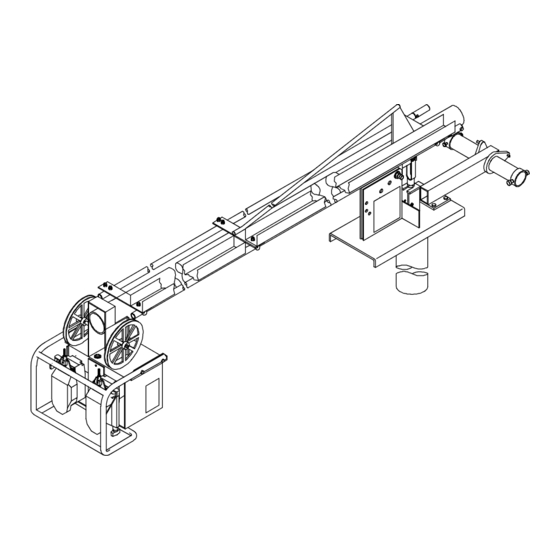
Page 24: Section 6 − Parts List
SECTION 6 − PARTS LIST Hardware is common and not available unless listed. 252641-C Figure 6-1. Main Assembly OM-252643 Page 20... - Page 25 Quantity Model Item Dia. Part Mkgs. Description Figure 6-1. Main Assembly ....201319 . . . Cable, Interconnecting (Includes) ....
- Page 26 Hardware is common and not available unless listed. 142306-M Figure 6-2. Boom Assembly OM-252643 Page 22...
- Page 27 Quantity Model Item Part Description Figure 6-2. Boom Assembly (Figure 6-1 Item 11) ... . . 010313 Pin, Cotter Hair .072 X 1.437 ......
- Page 28 Hardware is common and not available unless listed. See Table 6-1 For Drive Roll & Wire Guide Kits 802 977-E Figure 6-3. Drive Assembly, Wire Quantity Model Item Dia. Part Mkgs. Description Figure 6-3. Drive Assembly, Wire (Figure 6-1 Items 24 and 28) .
- Page 29 Quantity Model Item Dia. Part Mkgs. Description Figure 6-3. Drive Assembly, Wire (continued) . . . M1,101 ..201231 . . . Motor, Gear 1/8HP 24VDC High Speed ... . .
- Page 30 Hardware is common and not available unless listed. ST-081 760-C Figure 6-4. Support, Hub & Reel Item Part Description Quantity Figure 6-4. Support, Hub and Reel (Figure 6-1 Item 9) ..058427 Ring, Retaining Spool .
- Page 31 Table 6-1. Drive Roll And Wire Guide Kits OM-252643 Page 27...
- Page 32 Notes...
- Page 33 Notes Start Your Professional Over 80,000 trained 400 Trade Square East, Troy, Ohio 45373 Welding Career Now! since 1930! 1-800-332-9448 www.welding.org...
- Page 34 Notes...
- Page 35 Effective January 1, 2017 (Equipment with a serial number preface of MH or newer) This limited warranty supersedes all previous Miller warranties and is exclusive with no other guarantees or warranties expressed or implied. Warranty Questions? LIMITED WARRANTY − Subject to the terms and conditions below, 6 Months —...
- Page 36 Contact the Delivering Carrier to: File a claim for loss or damage during shipment. For assistance in filing or settling claims, contact your distributor and/or equipment manufacturer’s Transportation Department. © ORIGINAL INSTRUCTIONS − PRINTED IN USA 2017 Miller Electric Mfg. Co. 2017−01...
Need help?
Do you have a question about the D-74 Boom w/Drives and is the answer not in the manual?
Questions and answers