
Subscribe to Our Youtube Channel
Related Manuals for Volvo TEREX TR100


Summary of Contents for Volvo TEREX TR100
- Page 1 TR100 RIGID TRUCKS TRUCKS MOT05113 Maintenance Manual Issue Date: 01-AUG-2019 Language: English (en) Revision No: Reference No: 15272903 Product Identification: TELR7831 Original Instructions © TEREX TRUCKS 2019...
- Page 2 Volvo Construction Equipment Haulers Ltd Newhouse Industrial Estate Motherwell, ML1 5RY United Kingdom Tel: +44 (0) 1698 737121 Fax: +44 (0) 1698 503210 www.terextrucks.com Product Identification Number Year of Construction Date of Delivery Dealer Stamp Notice Find manuals at https://best-manuals.com...
- Page 3 For further information on the subject matter detailed within this Maintenance Manual, please refer to Terex Trucks Operators Manuals and Illustrated Parts Catalouges. Alternatively, please contact; Technology Department Terex Equipment Limited Newhouse Industrial Estate Motherwell, ML1 5RY Tel; +44 (0) 1698 732121 Fax;...
-
Page 4: Important Safety Notice
IMPORTANT SAFETY NOTICE Proper service and repair is important to the safe, reliable operation of all motor vehicles. The service procedures recommended and described in this publication, are effective methods for performing service operations. Some of these service operations require the use of tools specially designed for the purpose. The special tools should be used when, and as recommended. - Page 5 TABLE OF CONTENTS Section No. Description SM No. GENERAL INFORMATION 0000 TR100 Off-Highway Truck 1618 Rev 6 0010 Welding Procedure 2172 CHASSIS 0010 Chassis, Hood and Fenders 1898 Rev 1 ENGINE 0030 Engine and Mounting 1655 Rev 2 0050 Air Cleaner 1246 0130 Power Takeoff...
- Page 6 TABLE OF CONTENTS Section No. Description SM No. STEERING SYSTEM 0000 Steering System Schematic 1661 Rev 2 0050 Steering Pump 2575 Rev 2 0080 Accumulator 1205 Rev 1 0090 Steering Valve 1640 Rev 2 0110 Double Relief Valve 1208 Rev 1 0120 Steering Cylinder and Linkage 1641 Rev 2...
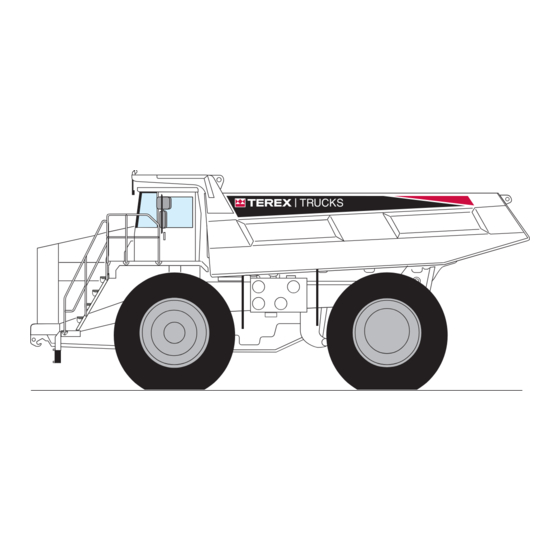
- Page 7 GENERAL INFORMATION - TR100 Mining Truck Section 000-0000 MOT05117 1 635 Body (5-4) Depth 5 150 (16-11) 4 730 (15-6) 1 220 (4-0) (2-7) 1 755 (5-9) 8 960 Vehicle Clearance Diameter (SAE) 24.5 m (80 ft) (29-5) 3 420 (11-3) 5 080 (16-8) 8 640 (28-4)
- Page 8 General Information - TR100 Mining Truck Section 000-0000 DRIVE AXLE Parking Heavy duty axle with full floating axle shafts, single Application of rear brakes by springs in brake disc pack. reduction spiral bevel gear differential and planetary Hydraulically released. reduction at each wheel. Hold-off Pressure ........
- Page 9 General Information - TR100 Mining Truck Section 000-0000 BODY Hands and Arm Vibration Longitudinal 'V' type floor with integral transverse box- The weighted root mean square acceleration to which section stiffeners. The body is exhaust heated and rests on hand and arms of the operator are exposed is less resilient impact absorption pads.
- Page 10 General Information - TR100 Mining Truck Section 000-0000 THIS PAGE IS INTENTIONALLY BLANK SM 1618 Rev6 03 -19 Find manuals at https://best-manuals.com...
- Page 11 GENERAL INFORMATION - Welding Procedure Section 000-0010 Welding WARNING Welding and flame cutting cadmium plated metals produce odourless fumes which are WARNINGS toxic. Recommended industrial hygiene Before any welding is done on a machine practice for protection of the welding operator equipped with any electronic systems, from the cadmium fumes and metallic oxides disconnect the following (if applicable) in...
- Page 12 General Information - Welding Procedure Section 000-0010 3. Pre-heat area to 100° C (212° F), measured 3 - 4" 3 - 4" either side of repair prior to gouging. On either side of repair. Avoid local overheating. completion of gouging grind to remove thin carbon layer.
-
Page 13: Installation
CHASSIS - Chassis, Hood and Fenders Section 100-0010 MOT04727 MOT04727 1 - Frame Assembly 11 - Spring Disc 2 - Bushing 5 - Nut 8 - Hardened Washer 12 - Hardened Washer 3 - Engine Guard 6 - Hardened Washer 9 - Bolt 13 - Hardened Spacer 4 - Transmission Guard... -
Page 14: Maintenance
Chassis - Chassis, Hood and Fenders Section 100-00100 MOT00003 MOT00003 LOCK 9268885 KEYS 9268892 16 LH 17 RH 1 - Hood Assembly 6 - Locknut 10 - Bracket 14 - Nut 2 - Door Assembly 7 - Hardened Washer 11 - Plate Assembly - Top 15 - Beading 3 - Latch Spring 8 - Plate Assembly - Base... -
Page 15: Special Tools
Chassis - Chassis, Hood and Fenders Section 100-0010 MOT00002 52, 63 SECT 'B-B' SECS. 260-0030 & 260-0040 33 40 40 33 40 33 40 24 40 21 SECT 'A-A' 1 - Fender Extension 20 - Bolt 56 - Lockwasher 38 - Hardened Washer 2 - Fender Assembly - LH 57 - Washer 21 - Bolt... - Page 16 Chassis - Chassis, Hood and Fenders Section 100-00100 MOT06285 34,32 12 7 12 1 12,7 1,11 40 41 1 - Bolt 12 - Hardened Washer 22 - Hoodside Assembly - LH 32 - Bolt 2 - Bolt 13 - Bolt 23 - Hoodside Assembly - RH 33 - Nut 3 - Bolt...
- Page 17 Chassis - Chassis, Hood and Fenders Section 100-0010 MOT05155 MOT05155 MIRROR MOUNTING 1 - Radiator Guard 11 - Lockwasher 5 - Button Plug 8 - Washer 2 - Grille 12 - Bolt 6 - Bolt 9 - Plate 3 - Bolt 13 - Angle Bracket 7 - Hardened Washer 10 - Clamp Plate...
- Page 18 Chassis - Chassis, Hood and Fenders Section 100-00100 P12241 P12241 1 - Mudguard 8 - Hardened Washer 15 - Clamp Plate 22 - Clamp Plate 2 - Clamp Plate 9 - Mudflap - LH 16 - Clamp Plate 23 - Clamp Plate 3 - Backing Plate 10 - Bracket - LH 17 - Mudflap - LH...
- Page 19 ENGINE - Engine and Mounting Section 110-0030 15 - Rear Mount 1 - Engine 29 - Coolant Filter 16 - Clamp 2 - Reducer Bush 30 - Lube Oil Filter 43 - Clip 17 - Latch 3 - Drain Cock 31 - Hand Hole Cover 44 - Dipstick 18 - Latch...
- Page 20 Engine - Engine and Mounting Section 110-0030 REMOVAL 6. If the vehicle is equipped with an air conditioning Numbers in parentheses refer to Fig. 1. system, evacuate refrigerant from the system and disconnect lines at the compressor. Refer to Section 260-0130, AIR CONDITIONING.
- Page 21 Engine - Engine and Mounting Section 110-0030 18. Identify all electrical harnesses and cables and transmission oil cooler from crossmember (6) attached to engine (1) assembly for ease of first. Refer to Section 210-0050, DISC BRAKE OIL installation and disconnect from engine (1) assembly. COOLER, and, Section 210-0060, TRANSMISSION OIL COOLER.
- Page 22 Engine - Engine and Mounting Section 110-0030 INSTALLATION SM - 1593 Numbers in parentheses refer to Fig. 1. Note: Tighten all fasteners without special torques specified to standard torques listed in Section Install coupling with 300-0080, STANDARD BOLT AND NUT TORQUE Part No.
-
Page 23: Cooling System
Engine - Engine and Mounting Section 110-0030 11. Connect front driveline to power takeoff and 24. If the vehicle is equipped with an air conditioning yoke assembly. Refer to Section 130-0010, FRONT system, connect the lines at the compressor as DRIVELINE. -
Page 24: Lubrication System
Engine - Engine and Mounting Section 110-0030 MAINTENANCE tighten by hand until the gasket contacts the filter Numbers in parentheses refer to Fig. 1, unless head surface. Tighten fuel filters (28) per the filter otherwise specified. manufacturer's instructions. Every 10 Hours (Daily) Note: Mechanical tightening of the filters is not General - Visually check the engine for leaks, loose or recommended, and may result in seal and/or cartridge... -
Page 25: Service Tools
Engine - Engine and Mounting Section 110-0030 Crankcase Breather - Check and clean the Apply a thin film of clean lubricating oil to the gasket crankcase breather hose. Remove the breather hose surface of the new filters and fill the filters with and check internally for obstructions or sludge buildup. - Page 26 Engine - Engine and Mounting Section 110-0030 THIS PAGE IS INTENTIONALLY BLANK SM 1655 Rev 2 06-14...
-
Page 27: Engine Air Cleaner
ENGINE - Air Cleaner Section 110-0050 SM - 1532 1 - Air Cleaner Body 2 - Primary Element 3 - Safety Element 4 - Cover Assembly 5 - Latch 6 - Vacuator Valve Fig. 1 - Exploded View of Air Cleaner DESCRIPTION SM - 1898 Numbers in parentheses refer to Fig. - Page 28 Engine - Air Cleaner Section 110-0050 SM - 1693 18,19 1 - Plenum Chamber 7 - Mounting Band 11 - Clamp 16 - Nipple 2 - LH Tube 8 - Hump Hose 12 - Bolt 17 - Elbow 3 - RH Tube 13 - Nut 18 - Air Restriction Gauge 9 - Hump Hose...
-
Page 29: Air Cleaner Assembly
Engine - Air Cleaner Section 110-0050 Check condition of clamps (10 & 11, Fig. 3), hump however, it should perform satisfactorily through hoses (8 & 9, Fig. 3) and plenum chamber (1, Fig. 3). approximately six cleanings, providing it does not rupture. Tighten/replace as necessary. -
Page 30: Secondary Element
Engine - Air Cleaner Section 110-0050 MEASURING AIR RESTRICTION 8. After primary element (2) is thoroughly dried, inspect for damage or ruptures, especially close to Numbers in parentheses refer to Fig. 3. the end caps. To detect paper ruptures, place a bright light bulb inside the element and rotate element slowly. - Page 31 This as a preview PDF file from best-manuals.com Download full PDF manual at best-manuals.com...
Need help?
Do you have a question about the TEREX TR100 and is the answer not in the manual?
Questions and answers