Advertisement
Quick Links
Installation Manual
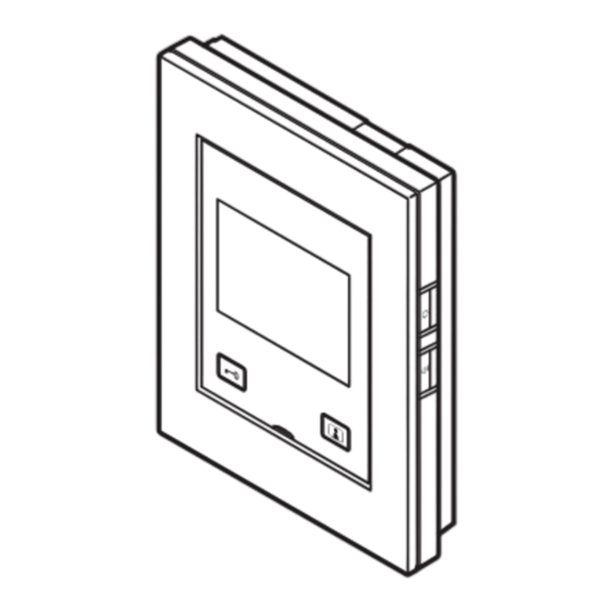
Parts names
JS-1MD / JS-1HD
The illustration is JS-1MD.
Color LCD screen
Remove protective film before use, if attached.
Door release button
Audio transmit
LED (orange)
Power switch
Talk/Off button
JS-DA
Camera-angle
Camera
adjustment lever
Microphone
The camera-angle adjustment lever is
on the back of the door station.
Mounting frame
[Back side]
Front panel
Camera-angle
Speaker
adjustment lever
Location LED (red)
Call button
White light LED
Drainage holes
Cable inlet holes
Included accessories
Installation
Information
Mounting bracket x1
manual x1
sheet x1
(attached to the monitor
(this manual)
station)
NOTES:
•
Mounting and wood mounting screws not included.
•
For details on the power supply, see the installation manual of the power supply separately.
Precautions
Prohibited
Do not dismantle unit
Warning
(Negligence could result in death or serious injury.)
1. Do not disassemble or modify the station. This may result in fire or electrical shock.
2. Do not use with a power supply rated above the specified voltage. This may result in fire or
electrical shock.
3. Do not install two power supplies in parallel to a single input. This may result in fire or
electrical shock.
4. Do not connect any terminals on the station directly to an AC power line. This may result in
fire or electrical shock.
5. Use the Aiphone power supply specific for use with the system. This may result in fire or
malfunction.
JSS-1A (A set includes JS-1MD, JS-DA, and power supply)
JS-1HD (Sub monitor station)
Caution
(Negligence could result in injury to people or damage to property.)
1. Do not install or connect the station with the power on. This may result in electrical shock
or malfunction.
2. Make sure the wiring is correct and there are no wiring shorts before switching on the
station. This may result in fire or electrical shock.
Microphone
3. Install in a place where the station will not get easily bumped. This may result in injury.
Monitor button
4. Do not put your ear close to the speaker when using the station. May cause harm to the
ear if a sudden loud noise is emitted.
Screen brightness
control button
Precautions for mounting
Volume control
button
1. The monitor station is designed for indoor use only. Do not install at outdoor location.
2. Installing the device in the following locations could cause malfunction:
* Locations under direct sunlight (except door station)
* Locations near heating equipment
Speaker
* Locations subject to liquid, iron filings, dust, oil, or chemicals
* Locations subject to moisture and humidity extremes
* Locations where the temperature is quite low
* Locations subject to steam or oil smoke
* Sulphurous environments
* Locations close to the sea or directly exposed to sea breeze
3. Installing the station in the following locations as is may affect the clarity of the image:
* Where lights will shine directly into the camera at night time
* Where the sky fills much of the background
* Where the background of the subject is white
* Where sunlight or other strong light sources will shine directly into the camera
Where the sky fills much of
the background
Sky
4. In 50Hz regions, if a strong fluorescent light enters directly into the camera, it may cause the
image to flicker. Either shield the camera from the light or use an inverter fluorescent light.
5. Use a parallel 2 conductor cable to connect the door station.
6. For wiring, separate them for audio/video and door release and keep them more than 10cm
(3-15/16") away from each other.
Front panel x1
7. If exisiting wiring is used, the device may not operate properly. In that case, it will be
(attached to the door
necessary to replace the wiring.
station, JSS-1A only)
8. Do not use any impact driver to fasten screws. Doing so may cause damage to the device.
9. Do not install the product on a recessed wall to avoid interruption of communication.
10. Using a single multi-conductor cable for multiple connections may result in poor image quality.
General Precautions
1. Install low-voltage lines at least 30 cm (12") away from high-voltage lines (AC100V-240V),
especially inverter air conditioner wiring. This may result in interference or malfunction.
Be sure to follow
2. When installing or using the station, give consideration to the privacy rights of subjects, as it
the instruction
is the responsibility of the system owner to post signs or warnings in accordance with local
ordinances.
Notice
1. If the station is used in areas where there are business-use wireless devices such as a
transceiver or mobile phones, it may cause malfunction.
2. If the station is installed near a wireless device, interference may occur and could cause a
malfunction.
3. If the station is installed in an area with an extremely strong electrical field, such as in the
vicinity of a broadcasting station, it may create interference and cause a malfunction.
4. Internal and external temperature difference may cause condensation on the camera.
Plugging cable holes and other gaps is recommended for preventing condensation.
Where the background of
Where sunlight or other
the subject is white
strong light sources will shine
directly into the camera
White
wall
Issue date: Oct. 2019 FK2685 A P1019 AQ 61458
Wiring method, wiring distance
A
JS-DA
JS-1MD
B
PS24
: PS-2420, PS-2420S, PS-2420UL,
PS-2420BF, PS-2420DM
Ø 0.65 mm
22 AWG
Ø 0.8-1.2 mm
A
50 m
165'
100 m
B
5 m
16'
10 m
Installation
Cable
•
Use PE (polyethylene)-insulated PVC jacket
cable.
Parallel or jacketed 2-conductor,
mid-capacitance non-shielded cable is
recommended.
•
Never use individual conductors, twisted pair cable or coaxial cable.
To connect low voltage wires, either crimp them with a crimp sleeve or solder
them, and then insulate by covering with insulating tape.
[Crimping with a crimp sleeve]
Crimp sleeve
1. Line up solid and
2. Overlap more than half
stranded conductors,
of the width and twist
and crimp them.
them at least twice.
Solid conductor
Stranded conductor
[Soldering]
1. Twist the stranded
2. Bend the tip and solder it.
conductor around the
Make sure no lead wire
solid conductor at least
sticks out.
three times.
Solid
Stranded
conductor
conductor
Soldering
•
When using existing cables
Check for short circuit and disconnection before installation.
Ø0.8-1.2mm, 100m (20-16 AWG, 330')
Loop resistance value: 6Ω or less
Disconnection check (6Ω or less)
Connect the ends of one side and make a measure at the other side with a tester.
Connect the ends of
∞
Short circuit check:
Ω (Infinity)
one side.
Disconnect
Measure the resistance of this loop.
JS-1HD
B
20-16 AWG
330'
33'
Insulating tape
3. Overlap more than half of
the width and twist them at
least twice.
Insulating tape
Advertisement

Related Manuals for Aiphone JSS-1A


Summary of Contents for Aiphone JSS-1A
- Page 1 5. Use the Aiphone power supply specific for use with the system. This may result in fire or 4. Internal and external temperature difference may cause condensation on the camera.
- Page 2 Installation Mounting Installation location of the video door station and image view area JS-1MD / JS-1HD The illustration is JS-1MD. JS-DA <Back wiring> <Surface wiring> The wires can be routed to the top or bottom of the station. The angle of the camera lens can be adjusted in the range of 15° in the upward, Mounting bracket Remove the mounting Cut the cable inlet to allow passage of the wiring into the station from the top or bottom...
- Page 3 Installation Manual JSS-1A (A set includes JS-1MD, JS-DA, and power supply) JS-1HD (Sub monitor station) Issue date: Oct. 2019 FK2685 A P1019 AQ 61458 Mounting Wiring Technical precautions Insert wires securely into each station as shown below. Cleaning: JS-DA •...
Need help?
Do you have a question about the JSS-1A and is the answer not in the manual?
Questions and answers