Advertisement
Quick Links
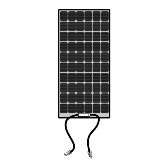
Thank you for purchasing the Xantrex Solar Max Flex Panel. The Xantrex Solar Max Flex Panel is a
high quality, carbon emissions-free, and sustainable power source for your vehicle such as,
recreational vehicle (RV), truck, or boat. It is designed to take solar energy and quietly produce power
for your vehicle's DC appliances and store energy to a battery during daylight hours.
The Solar Max Flex Panel base package includes the
following items:
one Solar Max Flex Panel
n
one Product Notice with a link to this Installation
n
Guide
NOTE: If any of the accessories, materials, and other
items are missing, contact Xantrex or any authorized
Xantrex dealer for replacement. See Contact Information
on the back cover.
The following Xantrex accessories are available to complete your solar system and are sold
separately:
Solar and Battery Cables Starter Kit (PN: 708-0150)
n
PWM 30A Charge Controller (PN: 709-3024-01)
n
MPPT 30A Charge Controller (PN: 710-3024-01)
n
MPPT Remote Display (PN: 710-0010)
n
Installation Guide
115W Solar Max Flex Panel
Model Number: 784-9115-01
115W Solar Max Flex Slim Panel
Model Number: 784-9115S-01
220W Solar Max Flex Panel
Model Number: 784-9220-01
330 Solar Max Flex Panel
Model Number: 784-0330
NOTE: Actualproduct maybe different from what isshown.
Advertisement

Related Manuals for Xantrex 784-9115-01


Summary of Contents for Xantrex 784-9115-01
- Page 1 Model Number: 784-0330 NOTE: Actualproduct maybe different from what isshown. Thank you for purchasing the Xantrex Solar Max Flex Panel. The Xantrex Solar Max Flex Panel is a high quality, carbon emissions-free, and sustainable power source for your vehicle such as, recreational vehicle (RV), truck, or boat.
- Page 2 THE ACCURACY CANNOT BE GUARANTEED. APPROVED CONTENT IS CONTAINED WITH THE ENGLISH LANGUAGE VERSION WHICH IS POSTED AT http://www.xantrex.com. NOTE: Visithttp://www.xantrex.com ,click Products, selecta Product category, selecta Product, and search the Product Documents panel for a translation ofthe English guide,ifavailable. Contact Information...
-
Page 3: Table Of Contents
Contents Basic Installation Steps Safety Instructions Tools and Materials Solar Panel Wiring Solar Panel Maintenance and Care Troubleshooting Specifications Accessory List 975-1029-01-01 Rev E February 2024... - Page 4 This page is intentionally blank.
-
Page 5: Basic Installation Steps
2"-wide 3M 4411 Extreme Sealing Tape 1. Plan the power system and where to mount the solar panel. a. The Xantrex Solar Max Flex Panel comes in the following power levels: 115 W standard, 115 W slim, 220 W, and 345 W b. - Page 6 2. Plan where to mount the charge controller, fuses, and cable locations. a. Identify and gather information about your vehicle. - Some vehicles are factory-installed with roof cable entry points. - If a cable entry point is absent, factory-installed vents can be used to route cables through. b.
- Page 7 3. Mount the solar panel. a. Unpack the solar panels and prepare all installation tools and TIP: Once applied to a surface, the 3M™ materials. VHB™ tape, which isa high-strength, double- sided acrylicadhesive tape, cannot be easily b. Prepare the roof mounting surface by removing dust, dirt, and removed without damaging both the solar debris.
- Page 8 Figure 4 Adhesive placement depending on surface sealing tape For illustration purposes. The solar cellsare shown asperspective only. Do not applythe adhesive tape on top of the solar cells. The adhesive tape must be applied on the backside of the paneland onto the mounting surface. 975-1029-01-01 Rev E February 2024...
- Page 9 4. Connect the DC cables. NOTICE REVERSE POLARITY Check polarity at all terminals before making the final DC connection. POS(+) (red) must connect to charge controller POS(+) (red); NEG(–) (black) must connect to charge controller NEG(–) (black). Failure to follow these instructions can result in equipment damage.
-
Page 10: Solar Panel Wiring
Solar Panel Wiring a. Depending on your power needs and installation type, you have two kinds of solar charge controllers available. Solar Charge Controller Output Voltage Part Number Pulse width modulation 12/24VDC 709-3024-01 Maximum power point tracking 12/24VDC 710-3024-01 b. Solar panels can be configured in series, parallel, or a combination of both series and parallel. Figure 5 Cable schematic for series Pos (+) of first panel connects to Neg (-) of next panel and so on and terminating with the Pos (+) of the solar charge controller. - Page 11 Figure 6 Cable schematic for parallel Pos (+) of first panel connects to Pos (+) of next panel using branch connectors and so on and terminating with the Pos (+) of the solar charge controller. Neg (-) of first panel connects to Neg (-) of next panel using branch connectors and so on and terminating with the Neg (-) of the solar charge controller.
-
Page 12: Solar Panel Maintenance And Care
Solar Panel Maintenance and Care Although a well designed vehicle-mounted solar system requires minimal maintenance, it is highly recommended to perform an inspection and cleaning of the solar panels during the warranty period. This helps to ensure optimal system performance and reliability through a few simple steps. Visual Perform a visual inspection of the solar system on a monthly basis to identify if there are Inspection... - Page 13 Diodes PV modules come equipped with bypass diodes in the junction box to minimize heating Inspection and current losses. Do not attempt to open the junction box to change the diodes if they malfunction, as it can pose electrical hazards and void the module's warranty. Battery If your system uses a battery, consider placing blocking diodes between the battery and System...
-
Page 14: Troubleshooting
ATC blade fuse. Specifications NOTE: Specifications are subject to change without prior notice. 115W Solar Max Flex Panel Part number 784-9115-01 Dimensions 37.5in x 28.4in x 0.08in (953mm x 722mm x 2mm) Unit weight 6.0 lbs.(2.7 kg) Cell Type... - Page 15 115W Solar Max Flex Slim Panel Part number 784-9115S-01 Dimensions 70.3in x 15.3in x 0.08in 1789mm x 390mm x 2mm) Unit weight 6.1 lbs.(2.8 kg) Cell Type Monocrystalline PERC Maximum power at STC* 115 W Maximum power voltage 22.1 V Maximum power current 5.2 A Open circuit voltage 27.4 V ...
-
Page 16: Accessory List
Accessory List Accessories (Sold Separately). Contact a Xantrex authorized dealer to order. PV Extension Cables 10AWG, 30A PV Single Connector (PN: 30A PV Branch Connector (PN: PV Connector Assembly Tool 15-ft (PN: 708-0030) 708-0040) 708-0050) (PN: 708-0060) Solar and Battery Cables Starter... - Page 17 [This page intentionally left blank]...
- Page 18 +1-800-670-0707 +1-408-987-6030 customerservice@xantrex.com https://xantrex.com/support/get-customer-support/ http://www.xantrex.com 975-1029-01-01 Rev E Printed in USA. February 2024...
Need help?
Do you have a question about the 784-9115-01 and is the answer not in the manual?
Questions and answers