Advertisement
Table of Contents
- 1 Table of Contents
- 2 Reference Manual
- 3 Safety Precaution
- 4 Specifications
- 5 Data
- 6 Outlines and Dimensions
- 7 Wiring Diagram
- 8 Wiring Specifications
- 9 Refrigerant System Diagram
- 10 Troubleshooting
- 11 Function Setting
- 12 Monitoring the Operation
- 13 Easy Maintenance Function
- 14 Disassembly Procedure
- 15 Remote Controller
- Download this manual
SPLIT-TYPE AIR CONDITIONERS
SERVICE MANUAL
Outdoor unit
[Model Name]
PUZ-SM100VKA2
PUZ-SM125VKA2
PUZ-SM140VKA2
PUZ-SM100YKA2
PUZ-SM125YKA2
PUZ-SM140YKA2
[Service Ref.]
PUZ-SM100VKA2.TH
PUZ-SM125VKA2.TH
PUZ-SM140VKA2.TH
PUZ-SM100YKA2.TH
PUZ-SM125YKA2.TH
PUZ-SM140YKA2.TH
R32
CONTENTS
1. REFERENCE MANUAL ·························· 2
2. SAFETY PRECAUTION ·························· 2
3. SPECIFICATIONS ································12
4. DATA ··················································13
5. OUTLINES AND DIMENSIONS ···············16
6. WIRING DIAGRAM ·······························17
7. WIRING SPECIFICATIONS ····················20
8. REFRIGERANT SYSTEM DIAGRAM ·······25
9. TROUBLESHOOTING ···························27
10. FUNCTION SETTING ····························74
DATA BY THE REMOTE CONTROLLER ··75
12. EASY MAINTENANCE FUNCTION ··········83
13. DISASSEMBLY PROCEDURE ···············85
14. REMOTE CONTROLLER ·······················91
PARTS CATALOG (OCB774)
January 2023
No.OCH774
REVISED EDITION-A
Revision:
• Connectable indoor units
have been added in
REVISED EDITION-A.
OCH774 is void.
Advertisement
Table of Contents

Related Manuals for Mitsubishi Electric PUZ-SM100VKA2


Summary of Contents for Mitsubishi Electric PUZ-SM100VKA2
-
Page 1: Table Of Contents
SPLIT-TYPE AIR CONDITIONERS January 2023 No.OCH774 SERVICE MANUAL REVISED EDITION-A Outdoor unit [Model Name] [Service Ref.] PUZ-SM100VKA2.TH PUZ-SM100VKA2 Revision: • Connectable indoor units PUZ-SM125VKA2.TH PUZ-SM125VKA2 have been added in REVISED EDITION-A. PUZ-SM140VKA2.TH PUZ-SM140VKA2 OCH774 is void. PUZ-SM100YKA2.TH PUZ-SM100YKA2 PUZ-SM125YKA2.TH PUZ-SM125YKA2 PUZ-SM140YKA2.TH... -
Page 2: Reference Manual
REFERENCE MANUAL INDOOR UNIT SERVICE MANUAL Service Manual No. Model Name Service Ref. Parts Catalog No. OCH784 PLA-SM71/100/125/140EA2 PLA-SM71/100/125/140EA2.UK OCB784 PEAD-SM50/60JA(L).UK — PEAD-SM71/100/125/140JA(L)2.UK BWE021470 PEAD-SM50/60JA(L) PEAD-SM71/100/125/140JA(L)2 PEAD-SM50/60JA(L).TH — BWE022250 PEAD-SM71/100/125/140JA(L)2.TH SAFETY PRECAUTION MEANINGS OF SYMBOLS DISPLAYED ON THE UNIT This mark is for R32 refrigerant only. Refrigerant type is written on nameplate of outdoor unit. WARNING Read the OPERATION MANUAL carefully before operation. - Page 3 Make sure that the inside and outside of Use the following tools specifically designed for refrigerant piping is clean and it has no use with R32 refrigerant. contaminants such as sulfur, oxides, dirt, The following tools are necessary to use R32 refrigerant. shaving particles, etc., which are hazard to Tools for R32 refrigerant cycle.
- Page 4 [1] Warning for service (1) Do not alter the unit. (2) For installation and relocation work, follow the instructions in the Installation Manual and use tools and pipe components specifically made for use with refrigerant specified in the outdoor unit installation manual. (3) Ask a dealer or an authorized technician to install, relocate and repair the unit.
- Page 5 [4] Cautions for unit using R32 refrigerant Basic work procedures are the same as those for conventional units using refrigerant R410A. However, pay careful attention to the following points. (1) Information on servicing (1-1) Checks on the Area Prior to beginning work on systems containing flammable refrigerants, safety checks are necessary to ensure that the risk of ignition is minimized.
- Page 6 (3) Repair to intrinsically Safe Components Do not apply any permanent inductive or capacitance loads to the circuit without ensuring that this will not exceed the permissible voltage and current permitted for the equipment in use. Intrinsically safe components are the only types that can be worked on while live in the presence of a flammable atmos- phere.
- Page 7 b) Isolate system electrically. c) Before attempting the procedure, ensure that: • mechanical handling equipment is available, if required, for handling refrigerant cylinders; • all personal protective equipment is available and being used correctly; • the recovery process is supervised at all times by a competent person; •...
- Page 8 2-3. PRECAUTIONS WHEN REUSING EXISTING R22/R410A REFRIGERANT PIPES (1) Flowchart • Refer to the flowchart below to determine if the existing pipes can be used and if it is necessary to use a filter dryer. • If the diameter of the existing pipes is different from the specified diameter, refer to technological data materials to confirm if the pipes can be used.
- Page 9 Flare cutting dimensions Flare nut dimensions Nominal Nominal Dimension B (mm) Dimension A ( )(mm) Outside Outside -0.4 dimensions dimensions R32/R410A diameter (mm) diameter (mm) R32/R410A (inch) (inch) 6.35 6.35 17.0 17.0 9.52 13.2 13.0 9.52 22.0 22.0 12.70 16.6 16.2 12.70 26.0...
- Page 10 2-5. Minimum installation area If you unavoidably install a unit in a space where all four sides are blocked or there are depressions, confirm that one of these situations (A, B or C) is satisfied. Note: These countermeasures are for keeping safety not for specification guarantee. A) Secure sufficient installation space (minimum installation area Amin).
- Page 11 ■ Indoor units Install in a room with a floor area of Amin or more, corresponding to refrigerant quantity M (factory-charged refrig- erant + locally added refrigerant). * For the factory-charged refrigerant amount, refer to the spec nameplate or installation manual. For the amount to be added locally, refer to the installation manual.
-
Page 12: Specifications
SPECIFICATIONS Service Ref Power supply Single phase, 230 V, 50 Hz 3-phase, 400 V, 50 Hz (phase, voltage, cycle) Max. current 26.5 11.5 External finish Munsell 3Y 7.8/1.1 Refrigerant control Linear Expansion Valve Compressor Hermetic Model SVB220FBGMT MVB33FBVMC SVB220FBAMT MVB33FBVMC Motor output Starter type Direct input... -
Page 13: Data
DATA 4-1. REFILLING REFRIGERANT CHARGE (R32: kg) Piping length (one way) Initial Service Ref. charged PUZ-SM100VKA2.TH PUZ-SM125VKA2.TH PUZ-SM140VKA2.TH PUZ-SM100YKA2.TH PUZ-SM125YKA2.TH PUZ-SM140YKA2.TH 4-2. COMPRESSOR TECHNICAL DATA (at 20°C) PUZ-SM125/140VKA2.TH Service Ref. PUZ-SM100VKA2.TH PUZ-SM100YKA2.TH PUZ-SM125/140YKA2.TH Compressor model SVB220FBGMT SVB220FBAMT MVB33FBVMC 0.95 1.64 0.88... - Page 14 4-3. NOISE CRITERION CURVES PUZ-SM100VKA2.TH PUZ-SM125VKA2.TH SPL(dB) SPL(dB) MODE LINE MODE LINE PUZ-SM100YKA2.TH PUZ-SM125YKA2.TH COOLING COOLING HEATING HEATING NC-70 NC-70 NC-60 NC-60 NC-50 NC-50 NC-40 NC-40 NC-30 NC-30 APPROXIMATE APPROXIMATE THRESHOLD OF THRESHOLD OF HEARING FOR NC-20 HEARING FOR NC-20...
- Page 15 Phase, Hz 1, 50 1, 50 1, 50 Voltage Current 0.46 0.44 0.66 0.64 0.66 0.64 Outdoor PUZ-SM100VKA2.TH PUZ-SM125VKA2.TH PUZ-SM140VKA2.TH PUZ-SM100YKA2.TH PUZ-SM125YKA2.TH PUZ-SM140YKA2.TH Phase, Hz 1, 50 3, 50 1, 50 3, 50 1, 50 3, 50 Voltage Current 12.1/4.3...
-
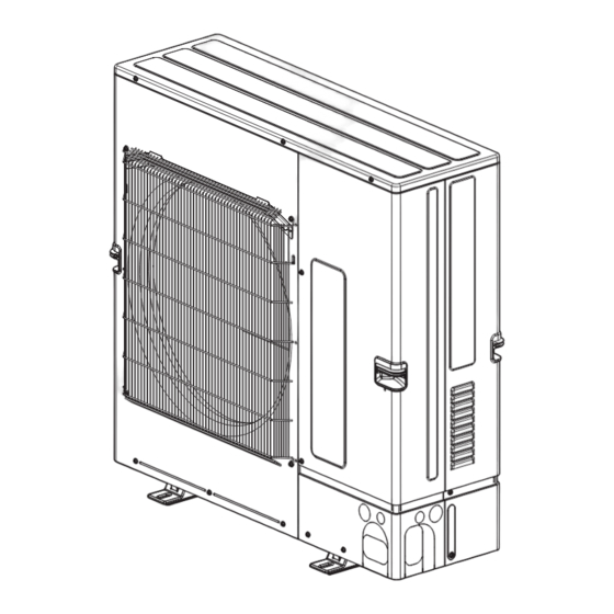
Page 16: Outlines And Dimensions
OUTLINES AND DIMENSIONS Unit: mm OCH774A... -
Page 17: Wiring Diagram
WIRING DIAGRAM PUZ-SM100VKA2.TH OCH774A... - Page 18 PUZ-SM125VKA2.TH PUZ-SM140VKA2.TH OCH774A...
- Page 19 PUZ-SM100YKA2.TH PUZ-SM125YKA2.TH PUZ-SM140YKA2.TH OCH774A...
-
Page 20: Wiring Specifications
WIRING SPECIFICATIONS 7-1. FIELD ELECTRICAL WIRING (power wiring specifications) Outdoor unit model PUZ-SM100/125VKA2 PUZ-SM140VKA2 PUZ-SM100/125/140YKA2 Outdoor unit power supply ~/N (single), 50 Hz, 230 V ~/N (single), 50 Hz, 230 V 3N~ (3 ph 4-wires), 50 Hz, 400 V Outdoor unit input capacity Main switch (Breaker) 32 A 40 A 16 A... - Page 21 7-2. SEPARATE INDOOR UNIT/ OUTDOOR UNIT POWER SUPPLIES The following connection patterns are available. The outdoor unit power supply patterns vary on models. 1:1 System The optional indoor power supply terminal kit is required. A Outdoor unit power supply B Earth leakage breaker C Wiring circuit breaker or isolating switch D Outdoor unit E Indoor unit/outdoor unit connecting cords...
- Page 22 7-3. INDOOR – OUTDOOR CONNECTING CABLE The cable shall not be lighter than design 60245 IEC or 60227 IEC. Wire No. o Size (mm²) Outdoor power supply Max. 45m Max. 50m Indoor unit-Outdoor unit 3 o 1.5 (polar) 3 o 2.5 (polar) Indoor unit-Outdoor unit earth 1 o Min 1.5 1 o Min 2.5...
- Page 23 7-4. M-NET WIRING METHOD (Points to note) (1) Outside the unit, transmission wires should stay away from electric wires in order to prevent electromagnetic noise from making an influence on the signal communication. Place them at intervals of more than 5 cm. Do not put them in the same conduit tube.
- Page 24 M-NET wiring (1) Use 2-core × 1.25mm² shield wire for electric wires. M-NET terminal (Excluding the case connecting to system controller.) Earth block wire (2) Connect the wire to the M-NET terminal block. Connect one core of the transmission wire (non-polar) to A terminal and the other to B. Peel the shield wire, twist the shield part to a string and connect it to S terminal.
-
Page 25: Refrigerant System Diagram
REFRIGERANT SYSTEM DIAGRAM Unit : mm (inch) Thermistor TH7 (Ambient) Heat exchanger Thermistor TH6 (Condenser) Stop valve 4-way valve Strainer Refrigerant GAS pipe connection [15.88 (5/8) Charge plug Distributor Muffler Charge plug High pressure switch 63H Thermistor TH3 (Liquid) Thermistor TH4 (Discharge) Thermistor TH33 Strainer... - Page 26 8-1. REFRIGERANT COLLECTING (PUMP DOWN) When relocating or disposing of the indoor/outdoor unit, pump down the system following the procedure below so that no refriger- ant is released into the atmosphere. 1. Turn off the power supply (circuit breaker). 2. Connect the low pressure valve on the gauge manifold to the charge plug (low pressure side) on the outdoor unit. 3.
-
Page 27: Troubleshooting
TROUBLESHOOTING 9-1. TROUBLESHOOTING <Check code display by self-diagnosis and actions to be taken for service (summary)> Present and past check codes are logged, and they can be displayed on the wired remote controller and control board of out- door unit. Actions to be taken for service, which depends on whether or not the trouble is reoccurring in the field, are summa- rized in the table below. - Page 28 • Refer to the following tables for details on the check codes. [Output pattern A] Beeper sounds Beep Beep Beep Beep Beep Beep Beep OPERATION · · · Repeated INDICATOR lamp blink pattern Approx. 2.5 s 0.5 s 0.5 s 0.5 s Approx.
- Page 29 9-3. SELF-DIAGNOSIS ACTION TABLE <Abnormalities detected when the power is ON> Abnormal points and detection method Judgment and action Check code Cause No voltage is supplied to termi- Check following items. nal block (TB1) of outdoor unit. a) Power supply breaker is a) Power supply breaker turned off.
- Page 30 Check code Abnormal points and detection method Cause Judgment and action Check disconnection or looseness or Contact failure or miswiring of Miswiring of indoor/outdoor unit polarity of indoor/outdoor unit connecting indoor/outdoor unit connecting connecting wire wire of indoor and outdoor units. wire 1.
- Page 31 <Abnormalities detected while unit is operating> Abnormal points and detection method Judgment and action Check code Cause High pressure (High pressure switch Short cycle of indoor unit – Check indoor unit and repair defect. Clogged filter of indoor unit 63H operated) Decreased airflow caused by Abnormal if high pressure switch 63H dirt of indoor fan...
- Page 32 Check airflow path for cooling. detects temperature indicated below. Failure of outdoor fan motor Check if there is something which causes PUZ-SM100VKA2 ······················ 71 °C Airflow path is clogged. temperature rise around outdoor unit. PUZ-SM125/140VKA2 ················ 74 °C Rise of ambient temperature (Upper limit of ambient temperature is 46°C.)
- Page 33 Abnormal point and detection method Judgment and action Check code Cause To find out the detail history (latest) about U9 error, turn ON SW2-1, 2-2 and 2-6. Detailed Refer to "9-9. FUNCTION OF SWITCHES, CONNECTORS AND JUMPERS". codes Overvoltage error Abnormal increase in power source Check the field facility for the power •...
- Page 34 From the previous page. Abnormal point and detection method Judgment and action Check code Cause Detailed PFC error (Overvoltage/ Abnormal increase in power Check the field facility for the power supply. codes Undervoltage/Overcurrent) source voltage • PFC detected any of the fol- Decrease in power source lowing: voltage, instantaneous stop...
- Page 35 Abnormal points and detection method Cause Judgment and action Check code Compressor overcurrent interruption Stop valve of outdoor unit is Open stop valve. Abnormal if overcurrent DC bus or com- closed. Check facility of power supply. pressor is detected after compressor starts Decrease of power supply voltage Correct the wiring (U W phase) to com-...
- Page 36 Check code Abnormal points and detection method Judgment and action Cause Remote controller transmission error (E3)/signal receiving error (E5) 2 remote controller are set as Set a remote controller to main, and the Abnormal if remote controller could not “main.” other to sub.
- Page 37 Check code Abnormal points and detection method Judgment and action Cause Abnormal if a connection of indoor unit Unauthorized connection of indoor Alter the connection referring to the combina- and outdoor unit which uses different unit and outdoor unit Connections tion as shown in the “cause”...
- Page 38 Check code Abnormal points and detection method Judgment and action Cause Abnormal refrigerant circuit Check refrigerant pipes for disconnection or Disconnection of or leakage in During Cooling or Auto Cooling operation, leakage. refrigerant pipes when the following are regarded as After the recovery of refrigerant, vacuum Air into refrigerant piping failures when detected for one second.
- Page 39 Check code Abnormal points and detection method Cause Judgment and action NO ACK signal Common factor that has no Always try the following when the error relation with abnormality source 1. Transmitting side controller detects “A7” occurs. The unit of former address abnormal if a message was transmitted does not exist as address but there is no reply (ACK) that a...
- Page 40 From the previous page. Check code Abnormal points and detection method Cause Judgment and action Same as mentioned in “A7” of the previous 4. If displayed address or attribute is During group operation with indoor unit of multi- refrigerant page. remote controller, indoor unit detects system, if indoor unit transmit abnormality when indoor unit transmits...
- Page 41 Check code Abnormal points and detection method Cause Judgment and action M-NET NO RESPONSE Transmitting condition is Check transmission waveform or noise on Abnormal if a message was transmitted repeated fault because of transmission wire. and there were reply (ACK) that message noise and the like.
- Page 42 Phenomena Factor Countermeasure 4. Even controlling by the wireless The pair number settings of the wireless remote Check the pair number settings. remote controller, no beep is controller and indoor controller board are heard and the unit does not start mismatched.
- Page 43 Symptoms: “Please Wait” is kept being displayed on the remote controller. Inspection method and Diagnosis flow Cause troubleshooting Check the display time of “Please Wait” after turning on the main power. 6 minutes 2 minutes or more or less How long is “Please Wait” •...
- Page 44 LED display of the indoor controller board Symptoms: Nothing is displayed on the remote controller 1 LED1 : LED2 : LED3 : Inspection method and Diagnosis flow Cause troubleshooting Check the voltage between S1 and S2 on the terminal block (TB4) of the indoor unit which is used to connect the indoor unit and the outdoor unit.
- Page 45 LED display of the indoor controller board Symptoms: Nothing is displayed on the remote controller 2 LED1 : LED2 : LED3 : Inspection method and Diagnosis flow Cause troubleshooting Check the voltage between S1 and S2 on the terminal block (TB4) of the indoor unit which is used to connect the indoor unit and the outdoor unit.
- Page 46 LED display of the indoor controller board Symptoms: Nothing is displayed on the remote controller 3 LED1 : LED2 : LED3 : — Inspection method and Diagnosis flow Cause troubleshooting Check the voltage of the terminal block (TB6) of the remote controller. 10 V DC to 16 V DC? •...
- Page 47 • Before repair <Frequent calls from customers> Phone Calls From Customers How to Respond Note Unit does 1 The operating display of remote 1 Check if power is supplied to air conditioner. not operate controller does not come on. Nothing appears on the display unless power is at all.
- Page 48 Phone Calls From Customers How to Respond Note Sound 4 A ticking sound is heard from 4 This is not a malfunction. comes out the outdoor unit sometimes. This is the sound which is heard when the fan of from the air the outdoor unit is controlling the airflow amount conditioner.
- Page 49 Phone Calls From Customers How to Respond Note A white mist is expelled from the indoor unit. This is not a malfunction. This may occur when the operation gets started in the room of high humidity. Water or moisture is expelled from the outdoor When pipes or piping joints are cooled, they get unit.
- Page 50 9-5. HOW TO CHECK THE PARTS Parts name Checkpoints Thermistor(TH3) Disconnect the connector then measure the resistance with a tester. (At the ambient temperature 10°C to 30°C) <Liquid> Thermistor (TH4) Normal Abnormal <Discharge> Thermistor (TH6) TH4, TH33 160 kΩ–410 kΩ <2-phase pipe>...
- Page 51 Check method of DC fan motor (fan motor / outdoor controller circuit board) Notes · High voltage is applied to the connector (CNF1) for the fan motor. Pay attention to the service. · Do not pull out the connector (CNF1) for the motor with the power supply on. (It causes trouble of the outdoor controller circuit board and fan motor.) Self check Symptom : The outdoor fan cannot turn around.
- Page 52 9-6. HOW TO CHECK THE COMPONENTS <Thermistor feature chart> Low temperature thermistors • Thermistor <Liquid> (TH3) • Thermistor <2-phase pipe> (TH6) • Thermistor <Ambient> (TH7) Thermistor R0 = 15 kΩ ± 3 % B constant = 3480 ± 1 % =15exp{3480( –...
- Page 53 Linear expansion valve (1) Operation summary of the linear expansion valve • Linear expansion valve opens/closes through stepping motor after receiving the pulse signal from the outdoor controller board. • Valve position can be changed in proportion to the number of pulse signal. <Connection between the outdoor controller board and the linear expansion valve>...
- Page 54 (3) How to attach and detach the coil of linear expansion valve <Composition> Linear expansion valve is separable into the main body and the coil as shown in the diagram below. Main body Stopper Coil Lead wire <How to detach the coil> Hold the lower part of the main body (shown as A) firmly so that the main body does not move and detach the coil by pulling it upward.
- Page 55 9-7. EMERGENCY OPERATION (1) When the check codes shown below are displayed on outdoor unit or microcomputer for wired remote controller or indoor unit has a failure, but no other problems are found, emergency operation will be available by setting the emergency opera- tion switch (SWE) on indoor controller board to ON and short-circuiting the connector (CN31) on outdoor controller board.
- Page 56 (5) Operation data during emergency operation During emergency operation, no communication is performed with the indoor unit, so the data items needed for operation are set to the following values: Operation mode Operation data Remarks COOL HEAT Intake temperature (TH1) 27°C 20.5°C Indoor liquid pipe temperature (TH2)
- Page 57 9-8. TEST POINT DIAGRAM Outdoor controller circuit board PUZ-SM100VKA2.TH PUZ-SM100YKA2.TH PUZ-SM125VKA2.TH PUZ-SM125YKA2.TH PUZ-SM140VKA2.TH PUZ-SM140YKA2.TH Manual defrost, CN51 CNDM detect history External signal output : Input of low-level sound priority mode record reset, • Compressor operating signal Demand control setting : Input of external contact point refrigerant address •...
- Page 58 Outdoor noise filter circuit board PUZ-SM100YKA2.TH PUZ-SM125YKA2.TH PUZ-SM140YKA2.TH LI1, LI2, LI3, NI POWER SUPPLY LI1-LI2/LI2-LI3/LI3-LI1 : 400 V AC input LI1-NI/LI2-NI/LI3-NI : 230 V AC input (Connect to the terminal block (TB1)) Connect to the elec- trical parts box CNAC1, CNAC2 230 V AC (Connect to the outdoor controller...
- Page 59 Outdoor power circuit board PUZ-SM100VKA2.TH Brief Check of POWER MODULE PUZ-SM125VKA2.TH If they are short-circuited, it means that they are broken. PUZ-SM140VKA2.TH Measure the resistance in the following points (connectors, etc.). 1. Check of POWER MODULE Check of DIODE circuit...
- Page 60 Outdoor power circuit board PUZ-SM100YKA2.TH PUZ-SM125YKA2.TH Brief Check of POWER MODULE If they are short-circuited, it means that they are broken. PUZ-SM140YKA2.TH Measure the resistance in the following points (connectors, etc.). 1. Check of DIODE MODULE L1 - P1 , L2 - P1 , L3 - P1 , L1 - N1 , L2 - N1 , L3 - N1 2.
- Page 61 Outdoor M-NET board (optional) Switch for communication LED11 LED13 display between LED12 Outdoor unit Receiving CN2M M-NET and outdoor board Transmitting connecting display Connect to M-NET Serial communication with outdoor board LED2 Energizing display of M-NET board (5V power supply) SW11 SW12 Power supply (5 V/12 V) input...
- Page 62 Action by the switch operation Type of Switch Function Effective timing Switch No function — — — Power failure Auto recovery No auto recovery When power supply ON automatic recovery 3,4,5,6 No function — — — Model select Demand function Low noise mode Always No function...
- Page 63 (2) Function of connector Action by open/short operation Types Connector Function Effective timing Short Open Connector CN31 Emergency operation Start Normal When power supply ON (3)Special function (a) Low-level sound priority mode (Local wiring) By performing the following modification, operation noise of the outdoor unit can be reduced by about 3-4 dB. The low noise mode will be activated when a commercially available timer or the contact input of an ON/OFF switch is added to the CNDM connector (option) on the control board of the outdoor unit.
- Page 64 <Display function of inspection for outdoor unit> The blinking patterns of both LED1 (green) and LED2 (red) indicate the types of abnormality when it occurs. Types of abnormality can be indicated in details by connecting an optional part ‘A-Control Service Tool (PAC-SK52ST)’ to connector CNM on outdoor controller board.
- Page 65 Indication Error Detailed Outdoor controller reference Check board Contents Inspection method page code LED1 (Green) LED2 (Red) 2 blinking 5 blinking Serial communication error 1. Check if connector (CN4) on outdoor controller <Communication between outdoor board and outdoor power board is not controller board and outdoor power board>...
- Page 66 <Outdoor unit operation monitor function> [When optional part ‘A-Control Service Tool (PAC-SK52ST)’ is connected to outdoor controller board (CNM)] Digital indicator LED1 displays 2 digit number or code to inform operation condition and the meaning of check code by controlling DIP SW2 on ‘A-Control Service Tool’. Operation indicator SW2 : Indicator change of self-diagnosis SW2 setting...
- Page 67 The black square ( ) indicates a switch position. SW2 setting Display detail Explanation for display Unit Discharge temperature (TH4) −20 to 217 −20 to 217 (When the discharge thermistor detects 100 °C or more, hundreds digit, tens digit and ones digit are displayed by turns.) °C (Example) When 105 °C;...
- Page 68 The black square ( ) indicates a switch position. SW2 setting Display detail Explanation for display Unit Discharge temperature (TH4) on error −20 to 217 occurring (When the temperature is 100 °C or more, the −20 to 217 hundreds digit, tens digit and ones digit are displayed by turns.) °C (Example) When 130 °C;...
- Page 69 The black square ( ) indicates a switch position. Display detail Explanation for display SW2 setting Unit 0 to 4 The number of connected indoor units (The number of connected indoor units are dis- played.) Unit 2 3 4 5 6 Capacity setting display Displayed as an outdoor capacity code.
- Page 70 The black square ( ) indicates a switch position. Display detail Explanation for display Unit SW2 setting Indoor setting temperature 17 to 30 17 to 30 °C 2 3 4 5 6 Outdoor 2-phase pipe (TH6) - 39 to 88 - 39 to 88 (When the temperature is 0°C or less, “–”...
- Page 71 The black square ( ) indicates a switch position. Display detail Explanation for display Unit SW2 setting DC bus voltage 0 to 500 (PUZ-SM·VKA2) 0 to 500 (PUZ-SM·VKA2) 0 to 1000 (PUZ-SM·YKA2) 0 to 1000 (PUZ-SM·YKA2) (When it is 100 V or more, hundreds digit, tens digit and ones digit are displayed by turns.) 2 3 4 5 6 0 to 100...
- Page 72 The black square ( ) indicates a switch position. Display detail Explanation for display Unit SW2 setting Indoor pipe temperature / Liquid (TH2) - 39 to 88 on error occurring (When the temperature is 0 °C or less, “–” and - 39 to 88 temperature are displayed by turns.) (Example) When -15 °C;...
- Page 73 The black square ( ) indicates a switch position. SW2 setting Display detail Explanation for display Unit - 39 to 88 Indoor pipe temperature / Liquid (When the temperature is 0 °C or less, “–” and (TH2 (3)) temperature are displayed by turns.) °C Indoor 3 2 3 4 5 6...
-
Page 74: Function Setting
FUNCTION SETTING 10-1. UNIT FUNCTION SETTING BY THE REMOTE CONTROLLER Each function can be set as necessary using the remote controller. The setting of function for each unit can only be done by the remote controller. Select function available from the <Table 1>. <Table 1>... -
Page 75: Monitoring The Operation
11 MONITORING THE OPERATION DATA BY THE REMOTE CONTROLLER 11-1. HOW TO "MONITOR THE OPERATION DATA" Refer to "14-10. REQUEST CODE" when monitoring the operation data. 11-2. Request code list Certain indoor/outdoor combinations do not have the request code function; therefore, no request codes are displayed. Description Request content Unit... - Page 76 Description Request content Unit Remarks (Display range) Indoor unit-Control state – Refer to "11-2-1.Detail Contents in Request Code". Outdoor unit-Control state – Refer to "11-2-1.Detail Contents in Request Code". Compressor-Frequency control state Refer to "11-2-1.Detail Contents in Request Code". – Outdoor unit-Fan control state Refer to "11-2-1.Detail Contents in Request Code".
- Page 77 Description Request content Unit Remarks (Display range) Error history 1 (latest) Displays the history. (" - - " is displayed if no history is present.) Code Error history 2 (second to last) Displays the history. (" - - " is displayed if no history is present.) Code Error history 3 (third to last) Displays the history.
- Page 78 Description Request content Unit Remarks (Display range) Indoor-Fan operating time 0 – 9999 1 hour (After filter is reset) Indoor-Total operating time 0 – 9999 10 hours (Fan motor ON time) Indoor fan output value (Sj value) 0 – 255 Fan control data –...
- Page 79 11-2-1. Detail Contents in Request Code Example) Request code "004" Discharge temperature 69 : Refrigerant address "00" A: Maintenance mode display B: Refrigerant address C: Data display area D: Request code display area [Operation state] (Request code :" 0") Relay output state Power currently Data display Display...
- Page 80 [Fan control state] (Request code :" 53 ") Data display Fan step correction value by heatsink temperature overheat prevention control Fan step correction value by cool condensation temperature overheat prevention control Display Correction value - (minus) – 1 [Actuator output state] (Request code :"54") Data display Actuator output state 1 Actuator output state 2...
- Page 81 [Contact demand capacity] (Request code : " 61") Setting content Data display Display Setting value Setting content 100% [External input state] (Request code : "62") Input state : Input present Data display Contact demand Silent mode Spare 1 Spare 2 Display Input state input...
- Page 82 [Indoor unit – Capacity setting information] (Request code : "163" ) Data display Display Capacity setting state Display Capacity setting state See the table on the right. [Wireless pair No. (indoor control board side) setting] (Request code :" 165") Data display Display Pair No.
-
Page 83: Easy Maintenance Function
EASY MAINTENANCE FUNCTION 12-1. SMOOTH MAINTENANCE 12-1-1. PAR-4xMAA ("x" represents 0 or later) Refer to "14-9. SMOOTH MAINTENANCE" for operation procedure. 12-1-2. PAR-21MAA ● Reduces maintenance work drastically. ● Enables you to check operation data of the indoor and outdoor units by remote controller. Furthermore, use of maintenance stable-operation control that fixes the operating frequency, allows smooth inspection, even for inverter models. - Page 84 <Guide for operation condition> Check Points Enter the temperature differences between into the graph given below. Operation state is determined according to the plotted areas on the graph. For data measurements, set the fan speed to "Hi" before activating maintenance mode. Inspection item Result Classification...
-
Page 85: Disassembly Procedure
DISASSEMBLY PROCEDURE : Indicates the visible parts in the photos/figures. : Indicates the invisible parts in the photos/figures. OPERATING PROCEDURE PHOTOS/FIGURES 1. Removing the service panel and top panel Photo 1 Top panel fixing screws Top panel (1) Remove 3 service panel fixing screws (5 × 12) and slide the hook on the right downward to remove the service Service panel panel. - Page 86 From the previous page. OPERATING PROCEDURE PHOTOS/FIGURES (8) Remove 2 electrical parts box fixing screws (4 × 10) and detach the electrical parts box by pulling it upward. The electrical parts box is fixed with 2 hooks on the left and 1 hook on the right.
- Page 87 From the previous page. OPERATING PROCEDURE PHOTOS/FIGURES 4. Disassembling the electrical parts box (YKA2 type) Photo 9 Electrical parts box (1) Disconnect all the connectors on the controller circuit board. (2) Remove the screw 1, that fix the plate equipped with the outdoor controller circuit board, and the electrical parts box.
- Page 88 PHOTOS/FIGURES OPERATING PROCEDURE 6. Removing the thermistor <Ambient> (TH7) Photo 13 Thermistor <Ambient> (TH7) (1) Remove the service panel. (See Photo 1) (2) Remove the top panel. (See Photo 1) (3) Disconnect the connector TH7/6 (red) on the controller circuit board in the electrical parts box. (4) Loosen the 2 wire clamps on top of the electrical parts box.
- Page 89 OPERATING PROCEDURE PHOTOS/FIGURES 8. Removing LEV coil Photo 18 (1) Remove the service panel. (See Photo 1) (2) Remove the top panel. (See Photo 1) (3) Remove the LEV coil by sliding the coil upward. (See Photo 19) (4) Disconnect the connectors, LEV-B (RD) on the controller circuit board in the electrical parts box.
- Page 90 OPERATING PROCEDURE PHOTOS/FIGURES 11. Removing the 4-way valve coil (21S4) Photo 20 (1) Remove the service panel. (See Photo 1) [Removing the 4-way valve coil] (2) Remove 4-way valve coil fixing screw (M5 × 6.5). (3) Remove the 4-way valve coil by sliding the coil toward you. (4) Disconnect the connector 21S4 (green) on the outdoor multi controller circuit board in the electrical parts box.
-
Page 91: Remote Controller
REMOTE CONTROLLER 14-1. REMOTE CONTROLLER FUNCTIONS <PAR-41MAA> Controller interface The functions of the function buttons change depending on the screen. Refer to the button function guide that appears at the bottom of the LCD for the functions they serve on a given screen. When the system is centrally controlled, the button function guide that corresponds to the locked button will not appear. - Page 92 Display The main display can be displayed in two different modes: ˝Full˝ and ˝Basic˝. The initial setting is ˝Full˝. To switch to the ˝Basic˝ mode, change the setting on the Main display setting. (Refer to operation manual included with remote controller.) <Full mode>...
- Page 93 Menu structure Main menu Press the button. Move the cursor to the desired item with the buttons, and press the button. Operation Vane · 3D i-See · Vent. (Lossnay) High power Comfort Manual vane angle 3D i-See sensor Vertical air direction Horizontal air direction Timer menu Timer...
- Page 94 Continue from the previous page. Maintenance menu Error information Filter information Cleaning Auto descending panel Descending operation Descending adjustment Service menu Test run menu Test run Drain pump test run Maintenance information Collect model names and serial No. Model name input Serial No.
- Page 95 Main menu list Main Setting and display items Setting details menu Operation Vane · 3D i-See · Vent. Vane: Use to set the vertical air direction. (Vane.Vent. (Lossnay)) Louver: Use to set the horizontal air direction. 3D i-See sensor: This setting is available only for the air conditioners that support easy setting function of motion sensing air direction.
- Page 96 Main Setting and display items Setting details menu Initial Basic Main/Sub When connecting 2 remote controllers, one of them needs to be designated as setting setting a sub controller. Clock Use to set the current time. Daylight Set the daylight saving time. saving time Administrator The administrator password is required to make the settings for the following...
- Page 97 <PAR-SL97A-E> Controller interface Transmission area Transmission indicator Remote controller display Timer indicator *For explanation purposes, all of the items that appear in the display are shown. *All items are displayed when the Reset button is pressed. Operation areas ON/OFF button Temperature setting buttons Fan Speed button (Changes fan speed) Timer Off button...
- Page 98 <PAR-SL100A-E> Controller interface Transmission area Remote controller display Set Temperature buttons OFF/ON button Mode button (Changes operation mode) Fan Speed button (Changes fan speed) Airflow button (Changes up/ i-see button* down airflow direction) Timer ON button Menu button Timer OFF button SET/SEND button Weekly timer ON/OFF button* CANCEL button...
- Page 99 14-2. ERROR INFORMATION When an error occurs, the following screen will appear. Check the error status, stop the operation, and consult your dealer. 1. Check code, error unit, refrigerant address, date and time of occur- Error information rence, model name, and serial number will appear. Error code The model name and serial number will appear only if the informa- Error unit...
- Page 100 • Checking the error information Maintenance menu While no errors are occurring, page 2/2 of the error information can be Error information viewed by selecting ˝Error information˝ from the Maintenance menu. Filter information Errors cannot be reset from this screen. Cleaning Main menu: Cursor...
- Page 101 14-3. SERVICE MENU Maintenance password is required 1. Select ˝Service˝ from the Main menu, and press the [ ] button. Main Main menu *At the main display, the menu button and select ˝Service˝ to make the maintenance setting. Service 2. When the Service menu is selected, a window will appear asking for the pass- Service menu word.
- Page 102 14-4. TEST RUN 14-4-1. PAR-41MAA 1. Select ˝Service˝ from the Main menu, and press the [ ] button. Test run Input maintenance info. Settings Check Select ˝Test run˝ with the F1 or F2 button, and press the [ Others ] button. 2.
- Page 103 14-4-2. PAR-SL97A-E Measure an impedance between the power supply terminal block on the outdoor unit and ground with a 500 V Megger and check that it is equal to or greater than 1.0 MΩ. TEST RUN 1. Turn on the main power to the unit. TEST RUN 2.
- Page 104 14-5. FUNCTION SETTING 14-5-1. PAR-41MAA Settings menu 1. Select ˝Service˝ from the Main menu, and press the [ ] button. Function setting Rotation setting Select ˝Setting˝ from the Service menu, and press the [ ] button. Service menu: Select ˝Function setting˝, and press the [ ] button.
- Page 105 Pattern 2 Function setting Ref. address Grp. (1/8) 4. Toggle through the pages with the F3 or F4 button. Mode 1 Mode 2 Mode 3 5. Select the mode number with the F1 or F2 button, and then press the [ Mode 4 button.
- Page 106 14-5-2. PAR-SL97A-E Functions can be selected with the wireless remote controller. Function selection using wireless remote controller is available only for refriger- ant system with wireless function. Refrigerant address cannot be specified by the wireless remote controller. [Flow of function selection procedure] Flow of function selection procedure The flow of the function selection procedure is shown below.
- Page 107 14-5-3. PAR-SL100A-E 1. Going to the function select mode Press the button between of 5 seconds. (Start this operation from the status of remote controller display turned off.) [CHECK] is lit and ˝00˝ blinks. (Fig. 1) Press the button to set the ˝50˝. Direct the wireless remote controller toward the receiver of the indoor unit and press the button.
- Page 108 14-6. ERROR HISTORY 1. Select ˝Service˝ from the Main menu, and press the [ ] button. Test run Input maintenance info. Settings Check Others Select ˝Check˝ with the F1 or F2 button, and press the [ button. Select ˝Error history˝ with the F1 or F2 button, and press the [ ] button.
- Page 109 5. Preliminary error history Preliminary error history Error Unt# dd/mm/yy Select "Preliminary error history" from the Error history menu, and press the [ ] button. 32 preliminary error history records will appear. Error history menu: Page Delete 4 records are shown per page, and the top record on the first page indi- cates the latest error record.
- Page 110 14-7. SELF-DIAGNOSIS 14-7-1. PAR-41MAA 1. Select ˝Service˝ from the Main menu, and press the [ ] button. Diagnosis Self check Select ˝Check˝ from the Service menu, Remote controller check and press the [ ] button. Service menu: Select ˝Diagnosis˝ from the Check menu, Cursor and press the [ ] button.
- Page 111 14-7-2. PAR-SL97A-E When a malfunction occurs to air conditioner, both indoor unit and outdoor unit will stop and operation lamp blinks to inform unusual stop. < Malfunction-diagnosis method at maintenance service> Refrigerant [Procedure] address display 1. Press the CHECK button twice. CHECK •...
- Page 112 14-8. REMOTE CONTROLLER CHECK If operations cannot be completed with the remote controller, diagnose the remote controller with this function. 1. Select ˝Service˝ from the Main menu, Diagnosis and press the [ ] button. Self check Remote controller check Select ˝Check˝ from the Service menu, and press the [ ] button.
- Page 113 14-9. SMOOTH MAINTENANCE 1. Select ˝Service˝ from the Main menu, and press the [ ] button. Check menu Error history Diagnosis Smooth maintenance Request code Select ˝Check˝ with the F1 or F2 button, and press the [ ] button. Service menu: Cursor Select ˝Smooth maintenance˝...
- Page 114 ■ Refrigerant address Single refrigerant system Multi refrigerant system (group control) In the case of single refrigerant system, the refrigerant address Up to 16 refrigerant systems (16 outdoor units) can be con- is ˝00˝ and no operation is required. nected as a group by 1 remote controller. To check or set the Simultaneous twin, triple units belong to this category refrigerant addresses.
- Page 115 OCH774A...
- Page 116 HEAD OFFICE: TOKYO BUILDING, 2-7-3, MARUNOUCHI, CHIYODA-KU, TOKYO 100-8310, JAPAN ©Copyright 2022 MITSUBISHI ELECTRIC CORPORATION Issued: Jan. 2023 No. OCH774 REVISED EDITION-A Published: May 2022 No. OCH774 Specifications are subject to change without notice. Made in Japan...
Need help?
Do you have a question about the PUZ-SM100VKA2 and is the answer not in the manual?
Questions and answers