Table of Contents
Advertisement
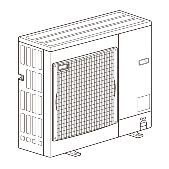
SERVICE MANUAL
Outdoor unit
[Model Name]
[Service Ref.]
PUZ-A18NHA6
PUZ-A18NHA6
PUZ-A24NHA6
PUZ-A24NHA6
PUZ-A30NHA6
PUZ-A30NHA6
PUZ-A36NHA6
PUZ-A36NHA6
PUZ-A42NHA6
PUZ-A42NHA6
PUZ-A18NHA6-BS
PUZ-A18NHA6-BS
PUZ-A24NHA6-BS
PUZ-A24NHA6-BS
PUZ-A30NHA6-BS
PUZ-A30NHA6-BS
PUZ-A36NHA6-BS
PUZ-A36NHA6-BS
PUZ-A42NHA6-BS
PUZ-A42NHA6-BS
PUY-A12NHA6
PUY-A12NHA6
PUY-A18NHA6
PUY-A18NHA6
PUY-A24NHA6
PUY-A24NHA6
PUY-A30NHA6
PUY-A30NHA6
PUY-A36NHA6
PUY-A36NHA6
PUY-A42NHA6
PUY-A42NHA6
PUY-A12NHA6-BS
PUY-A12NHA6-BS
PUY-A18NHA6-BS
PUY-A18NHA6-BS
PUY-A24NHA6-BS
PUY-A24NHA6-BS
PUY-A30NHA6-BS
PUY-A30NHA6-BS
PUY-A36NHA6-BS
PUY-A36NHA6-BS
PUY-A42NHA6-BS
PUY-A42NHA6-BS
PUZ-A24/30/36NHA6
PUY-A24/30/36NHA6
R410A
CONTENTS
1. REFERENCE MANUAL ································· 2
2. SAFETY PRECAUTION ································· 2
3. FEATURES ····················································· 6
4. SPECIFICATIONS ·········································· 7
5. DATA ······························································· 9
6. OUTLINES AND DIMENSIONS ··················· 13
7. WIRING DIAGRAM ······································ 16
8. WIRING SPECIFICATIONS ·························· 20
9. REFRIGERANT SYSTEM DIAGRAM ············· 23
10. TROUBLESHOOTING ·································· 26
11. EASY MAINTENANCE FUNCTION·············· 91
12. FUNCTION SETTING ··································· 95
14. DISASSEMBLY PROCEDURE ··················· 114
PARTS CATALOG (OCB577)
August 2015
No. OCH577
REVISED EDITION-A
Notes:
Advertisement
Table of Contents

Subscribe to Our Youtube Channel
Related Manuals for Mitsubishi Electric PUZ-A18NHA6


Summary of Contents for Mitsubishi Electric PUZ-A18NHA6
-
Page 1: Table Of Contents
August 2015 No. OCH577 SERVICE MANUAL R410A REVISED EDITION-A Outdoor unit [Model Name] [Service Ref.] PUZ-A18NHA6 PUZ-A18NHA6 PUZ-A24NHA6 PUZ-A24NHA6 PUZ-A30NHA6 PUZ-A30NHA6 PUZ-A36NHA6 PUZ-A36NHA6 PUZ-A42NHA6 PUZ-A42NHA6 PUZ-A18NHA6-BS PUZ-A18NHA6-BS PUZ-A24NHA6-BS PUZ-A24NHA6-BS PUZ-A30NHA6-BS PUZ-A30NHA6-BS PUZ-A36NHA6-BS PUZ-A36NHA6-BS PUZ-A42NHA6-BS PUZ-A42NHA6-BS Notes: PUY-A12NHA6 PUY-A12NHA6 PUY-A18NHA6 PUY-A18NHA6... -
Page 2: Reference Manual
REFERENCE MANUAL INDOOR UNIT SAFETY PRECAUTION 2-1. ALWAYS OBSERVE FOR SAFETY Before obtaining access to terminal, all supply circuits must be disconnected. Preparation before the repair service. Precautions during the repair service. - Page 3 2-2. CAUTIONS RELATED TO NEW REFRIGERANT Cautions for units utilizing refrigerant R410A Use a vacuum pump with a reverse flow check Use new refrigerant pipes. valve. In case of using the existing pipes for R22, be careful with Vacuum pump oil may flow back into refrigerant cycle and the following: that can cause deterioration of refrigerant oil, etc.
- Page 4 [1] Cautions for service (1) Perform service after recovering the refrigerant left in unit completely. (2) Do not release refrigerant in the air. (3) After completing service, charge the cycle with specified amount of refrigerant. (4) When performing service, install a filter drier simultaneously. Be sure to use a filter drier for new refrigerant.
- Page 5 Flare cutting dimensions Flare nut dimensions Dimension A ( Nominal Outside Dimension B Nominal Outside -0.4 dimensions (in) diameter (mm) (in [mm]) R22 (mm) (in [mm]) (mm) R410A dimensions (in) diameter (mm) R410A 11/32-23/64 [ 9.1] 6.35 6.35 43/64 [17.0] 17.0 1/2-33/64 [13.2]...
-
Page 6: Features
FEATURES PUZ-A18NHA6 PUZ-A24/30/36NHA6 PUZ-A18NHA6-BS PUZ-A24/30/36NHA6-BS PUY-A12/18NHA6 PUY-A24/30/36NHA6 PUY-A12/18NHA6-BS PUY-A24/30/36NHA6-BS PUZ-A42NHA6 PUZ-A42NHA6-BS PUY-A42NHA6 PUY-A42NHA6-BS CHARGELESS SYSTEM PRE-CHARGED REFRIGERANT IS SUPPLIED FOR PIPING LENGTH AT SHIPMENT. (Maximum 100 ft [30 m] (A42)/ Maximum 70 ft [21 m] (A12–36)) -
Page 7: Specifications
SPECIFICATIONS Service Ref. PUZ-A18NHA6 PUZ-A24NHA6 PUZ-A30NHA6 PUZ-A36NHA6 PUZ-A42NHA6 PUZ-A18NHA6-BS PUZ-A24NHA6-BS PUZ-A30NHA6-BS PUZ-A36NHA6-BS PUZ-A42NHA6-BS Power supply Phase Single Cycle 60 Hz Voltage 208/230 V MOCP Breaker size External finish Munsell 3Y 7.8/1.1 Heat exchanger Plate fin coil Defrost method Reverse cycle... - Page 8 Service Ref. PUY-A12NHA6 PUY-A18NHA6 PUY-A24NHA6 PUY-A30NHA6 PUY-A36NHA6 PUY-A42NHA6 PUY-A12NHA6-BS PUY-A18NHA6-BS PUY-A24NHA6-BS PUY-A30NHA6-BS PUY-A36NHA6-BS PUY-A42NHA6-BS Power supply Phase Single Cycle 60 Hz Voltage 208/230 V MOCP Breaker size External finish Munsell 3Y 7.8/1.1 Heat exchanger Plate fin coil Defrost method Crankcase heater Compressor Hermetic Model...
-
Page 9: Data
– – – – – – 5-2. COMPRESSOR TECHNICAL DATA ( at 68°F [20°C ] ) PUZ-A24 / 30 / 36NHA6 PUZ-A18NHA6 PUZ-A42NHA6 PUZ-A24 / 30 / 36NHA6-BS PUZ-A18NHA6-BS PUZ-A42NHA6-BS Service Ref. PUY-A24 / 30 / 36NHA6 PUY-A42NHA6 PUY-A12/18NHA6 PUY-A24 / 30 / 36NHA6-BS... - Page 10 5-3. NOISE CRITERION CURVES PUY-A18NHA6 PUY-A12NHA6 PUY-A18NHA6-BS PUY-A12NHA6-BS MODE SPL(dB) LINE SPL(dB) MODE LINE PUZ-A18NHA6 COOLING COOLING PUZ-A18NHA6-BS HEATING NC-70 NC-70 NC-60 NC-60 NC-50 NC-50 NC-40 NC-40 NC-30 NC-30 APPROXIMATE APPROXIMATE THRESHOLD OF THRESHOLD OF HEARING FOR HEARING FOR NC-20...
- Page 11 230 V 230 V 230 V 230 V 230 V Current 0.33 A 0.36 A 0.36 A 0.57 A 1.00 A 0.94 A Outdoor unit model PUZ-A18NHA6 PUZ-A24NHA6 PUZ-A30NHA6 PUZ-A36NHA6 PUZ-A42NHA6 Phase Single Single Single Single Single Cycle 60 Hz...
- Page 12 5-4-2. Cooling only Representative matching PKA-A12HA6 PKA-A18HA6 PKA-A24KA6 PKA-A30KA6 PKA-A36KA6 PLA-A42BA6 Mode COOLING COOLING COOLING COOLING COOLING COOLING 12 , 000 18 , 000 24 , 000 30 , 000 34 , 200 42 , 000 Total Capacity BTU/h 4 , 600 Input 1,190 2,240...
-
Page 13: Outlines And Dimensions
OUTLINES AND DIMENSIONS PUZ-A18NHA6 PUZ-A18NHA6-BS PUY-A12/18NHA6 PUY-A12/18NHA6-BS Unit: mm<in> 400<15-25/32> 347.5<13-11/16> 33<1-5/16> drain hole Air intake Air intake 45.4<1-25/32> Air discharge 4-oval hole 40<1-9/16> Service panel 18<23/32> 23<29/32> 22<7/8> Service panel for charge plug 2- 22.2<7/8> 1/2 conduit hole Connection for liquid pipe Handle FLARE 6.35<1/4>... - Page 14 PUZ-A24/30/36NHA6 PUZ-A24/30/36NHA6-BS PUY-A24/30/36NHA6 PUY-A24/30/36NHA6-BS Unit: mm<in>...
- Page 15 PUZ-A42NHA6 PUZ-A42NHA6-BS PUY-A42NHA6 PUY-A42NHA6-BS Unit: mm<in>...
-
Page 16: Wiring Diagram
WIRING DIAGRAM PUZ-A18NHA6 PUZ-A18NHA6-BS PUY-A12/18NHA6 PUY-A12/18NHA6-BS [LEGEND] SYMBOL NAME SYMBOL NAME SYMBOL NAME Terminal Block<Power Supply, Indoor/Outdoor> Converter LED1,LED2 LED<Operation Inspection Indicators> Motor for Compressor Power Module F1,F2,F3,F4 Fuse<T6.3AL250V> Fan Motor CB1,CB2,CB3 Main Smoothing Capacitor Switch<Pump Down> 21S4 Solenoid Valve (Four-Way Valve) N.F. - Page 17 PUZ-A24NHA6 PUZ-A24NHA6-BS PUY-A24NHA6 PUY-A24NHA6-BS [LEGEND] SYMBOL NAME SYMBOL NAME SYMBOL NAME Terminal Block<Power Supply, Indoor/Outdoor> TABU/V/W Switch<Function Switch> Connection Terminal<U/V/W-Phase> Motor for Compressor LED1,LED2 Converter LED<Operation Inspection Indicators> Fan Motor Power Module F1,F2,F3,F4 Fuse<T6.3AL250V> 21S4 Solenoid Valve (Four-Way Valve) CB1,CB2,CB3 Main Smoothing Capacitor Switch<Pump Down>...
- Page 18 PUZ-A30/36NHA6 PUZ-A30/36NHA6-BS PUY-A30/36NHA6 PUY-A30/36NHA6-BS [LEGEND] SYMBOL NAME SYMBOL NAME SYMBOL NAME Terminal Block<Power Supply, Indoor/Outdoor > P.B. Power Circuit Board Switch<Test Operation> Motor for Compressor TABU/V/W Switch<Model Select, Function Switch> Connection Terminal<U/V/W-Phase> Fan Motor TABS/T Connection Terminal<L1/L2-Phase> Switch<Model Select> 21S4 Solenoid Valve (Four-Way Valve) TABP1/P2 Connection Terminal<DC Voltage>...
- Page 19 PUZ-A42NHA6 PUZ-A42NHA6-BS PUY-A42NHA6 PUY-A42NHA6-BS [LEGEND] SYMBOL NAME SYMBOL NAME SYMBOL NAME Terminal Block<Power Supply, Indoor/Outdoor > P.B. Power Circuit Board Switch<Test Operation> Motor for Compressor TABU/V/W Connection Terminal<U/V/W-Phase> Switch<Model Select, Function Switch> MF1,MF2 Fan Motor Switch<Model Select> TABS/T Connection Terminal<L1/L2-Phase> 21S4 Solenoid Valve (Four-Way Valve) TABP1/P2/P...
-
Page 20: Wiring Specifications
WIRING SPECIFICATIONS 8-1. INDOOR UNIT POWER SUPPLIED FROM OUTDOOR UNIT (A-control application) The following connection patterns are available. The outdoor unit power supply patterns vary on models. 1:1 System Simultaneous twin system A Outdoor unit power supply B Wiring circuit breaker or isolating switch C Outdoor unit D Indoor unit/outdoor unit connecting cords E Remote controller... - Page 21 8-2. SEPARATE INDOOR UNIT/OUTDOOR UNIT POWER SUPPLIES The following illustrations show available connection patterns. The outdoor unit power supply patterns vary on models. 1:1 System The optional indoor power supply terminal kit is required. Outdoor unit power supply Wiring circuit breaker or isolating switch Outdoor unit Indoor unit/outdoor unit connecting cords Remote controller...
- Page 22 8-3. INDOOR - OUTDOOR CONNECTING CABLE Wire No. o Size Outdoor power supply Max. 147 ft [45 m] Max. 164 ft [50 m] Max. 262 ft [80 m] 3 o AWG16(polar) 3 o AWG13(polar) 3 o AWG13(polar) and S3 separated Indoor unit-Outdoor unit Note: The maximum cable length may vary depending on the condition of installation, humidity or materials, etc.
-
Page 23: Refrigerant System Diagram
REFRIGERANT SYSTEM DIAGRAM PUZ-A18NHA6 PUZ-A18NHA6-BS Unit: mm (in) High pressure Service Stop valve port(check) protect switch (with service port) 4-way valve Outdoor heat exchanger (#50) Refrigerant GAS pipe Strainer Thermistor 12.7A({1/2) (TH6) Muffler Thermistor (TH3) Thermistor Thermistor (TH32) (TH33) Distributor... - Page 24 PUY-A12NHA6 PUY-A12NHA6-BS PUY-A18NHA6 PUY-A18NHA6-BS Unit: mm (in) Service port Stop valve High pressure (Check) (with service port) protect switch Outdoor heat exchanger (#50) Thermistor Strainer Refrigerant GAS pipe (TH6) 12.7A({1/2) Thermistor (TH3) Thermistor Thermistor (TH32) (TH33) Distributor Accumulator Refrigerant flow in cooling Compressor (#100) (#100)
- Page 25 1. Refrigerant collecting (pump down) Warning: When pumping down the refrigerant, stop the compressor before disconnecting the refrigerant pipes. The compressor may burst if air etc. get into it. 2. Refrigerant pipe airtight testing method Local pipe Sealed, same way for gas side Stop valve <Liquid side>...
-
Page 26: Troubleshooting
TROUBLESHOOTING 10-1. TROUBLESHOOTING <Check code displayed by self-diagnosis and actions to be taken for service (summary)> Unit conditions at service Check code Actions to be taken for service (summary) Judge what is wrong and take a corrective action according Displayed to “10-4. - Page 27 10-2-1. Test run for wired remote controller <PAR-30MAA> <PAR-31MAA> MENU RETURN SELECT ON/OFF Test run Input maintenance info. Function setting Check Self check Test run menu Test run Drain pump test run Service menu: Cursor Test run Remain Test run operation Pipe Cool Auto...
- Page 28 <Error information> When an error occurs, the following screen will appear. Check the error status, stop the operation, and consult your dealer. Error information Error code Error unit Ref. address Unt# Model name Serial No. Reset error: Reset button Page Reset Error information Contact information...
- Page 29 <Checking the error information> Main Main menu Restriction Energy saving Night setback Filter information Error information Main display: Cursor Page <Error history> Test run Input maintenance info. Function setting Check Self check Check menu Error history Refrigerant volume check Refrigerant leak check Smooth maintenance Request code Service menu:...
- Page 30 Test run [for IR wireless remote controller] " TEST COOL TEST RUN TEST RUN TEMP ON/OFF MODE COOL MODE HEAT AUTO STOP AUTO START MODE VANE VANE CHECK LOUVER TEST RUN RESET CLOCK Note: while following steps 2 to 7.
- Page 31 10-3. HOW TO PROCEED "SELF-DIAGNOSIS" 10-3-1. Self-diagnosis <PAR-30MAA> <PAR-31MAA> Test run Input maintenance info. Function setting Check Self check Ref. address Ref. address Error Unt # Return: When there is no error history Self check Ref. address Error Unt# Grp. ...
- Page 32 10-3-2. Remote controller check <PAR-30MAA> <PAR-31MAA> Maintenance password Remote controller check Remote controller check Start checking? Remote controller check results screen Remote controller check Start checking? Check the remote controller display and see if anything is displayed (including lines). Nothing will appear on the remote controller display if the correct voltage (8.5–12 V DC) is not supplied to the remote control- ler.
- Page 33 10-4. SELF-DIAGNOSIS ACTION TABLE <Abnormalities detected when the power is turned on> Abnormal point and detection method Judgment and action Check code Case —...
- Page 34 Check code Abnormal point and detection method Case Judgment and action 63H connector open Miswiring of indoor/outdoor unit connecting wire 4–6 Miswiring of indoor/outdoor unit connecting wire (converse wiring or disconnection) 1–8 Start-up time over...
- Page 35 <Abnormalities detected while unit is operating> Abnormal point and detection method Judgment and action Check code Case High pressure (High-pressure switch 1–6 63H operated) 9–2 4–6 High discharge temperature High comp. surface temperature...
- Page 36 Abnormal point and detection method Judgment and action Check code Case Open/short circuit of outdoor unit temperature thermistor (TH32) Open/short of outdoor unit thermistors (TH3, TH6, TH7, TH8 and TH33 ) Thermistors Open detection Short detection Symbol Name Thermistor <Liquid> 58°F [ 50:] or below 194°F [ 90:] or above Thermistor <2-phase pipe>...
- Page 37 Abnormal point and detection method Judgment and action Check code Case Outdoor fan motor Overvoltage error Undervoltage error Input current sensor error/ L1-phase open error Abnormal power synchronous signal PFC error (Overvoltage/ Undervoltage/Overcurrent) (A12–24N only)
- Page 38 Check Code Abnormal point and detection method Case Judgment and action PFC/IGBT error (Undervoltage) Compressor overcurrent interruption (When compressor locked) Current sensor error Abnormal low pressure (63L worked) 2–4 Compressor overcurrent interruption...
- Page 39 Abnormal point and detection method Judgment and action Check code Case Remote controller transmission error (E0)/signal receiving error (E4) 1–3 Remote controller control board Remote controller transmission error (E3)/ signal receiving error (E5) 4–6 Indoor/outdoor unit communication error (Signal receiving error) 2–4...
- Page 40 Judgment and action Abnormal point and detection method Check code Case Indoor/outdoor unit communication error (Signal receiving error) (Outdoor unit) 2–4 Indoor/outdoor unit communication error (Transmitting error) (Outdoor unit) 2–4 Non defined check code Serial communication error...
- Page 41 Abnormal point and detection method Judgment and action Check code Case 1–4 Pipe temperature Temperature display of indoor condenser/ Temperature display of indoor liquid pipe evaporator pipe Indoor 1 Indoor 1 Temperature display of indoor condenser/ Temperature display of indoor liquid pipe evaporator pipe Indoor 2 Indoor 2 A-Control Service Tool...
- Page 42 Check code Abnormal point and detection method Case Judgment and action Communication error with communica- tion processor NO ACK signal Always try the followings when the error “A7” occurs. ······ 1–5 1–5 1–5 1–6...
- Page 43 Check code Abnormal point and detection method Judgment and action Case Same as mentioned in “A7” of the previous page.
- Page 44 Check code Abnormal point and detection method Case Judgment and action M-NET NO RESPONSE ······ 10-5. TROUBLESHOOTING OF PROBLEMS Phenomena Factor Countermeasure...
- Page 45 Phenomena Factor Countermeasure...
- Page 46 Symptoms: “PLEASE WAIT” is kept being displayed on the remote controller. Inspection method and Diagnosis flow Cause troubleshooting Check the display time of “PLEASE WAIT” after turning on the main power. 6 minutes 2 minutes or more or less How long is “PLEASE WAIT” “PLEASE WAIT”...
- Page 47 LED display of the indoor controller board Symptoms: Nothing is displayed on the remote controller. 1 LED1 : LED2 : LED3 : Inspection method and Diagnosis flow Cause troubleshooting Check the voltage between S1 and S2 on the terminal block (TB4) of the indoor unit.
- Page 48 LED display of the indoor controller board Symptoms: Nothing is displayed on the remote controller. 2 LED1 : LED2 : LED3 : Inspection method and Diagnosis flow Cause troubleshooting Check the voltage between S1 and S2 on the terminal block (TB4) of the indoor unit.
- Page 49 controller board Symptoms: Nothing is displayed on the remote controller. 3 LED1 : LED2 : LED3 : — Diagnosis flow Cause troubleshooting Check the voltage of the terminal block (TB6) of the remote controller. 10 to 16 V DC? remote controller remote controller.
- Page 50 Frequent calling from customers Phone Calls From Customers How to Respond Note 1 The operating display of remote 1 Check if power is supplied to air conditioner. Unit does not operate controller does not come on. Nothing appears on the display unless power is at all.
- Page 51 Phone Calls From Customers How to Respond Note 1 Check the set temperature of remote controller. The room cannot be cooled or heated sufficiently. The outdoor unit cannot be operated if the set temperature is not appropriate. The outdoor unit operates in the following modes. COOL: When the set temperature is lower than the room temperature.
- Page 52 Phone Calls From Customers How to Respond Note Something Air blows out for a while after However, this control is also This is not a malfunction. is wrong HEAT operation is stopped. The blower is operating just for cooling down the applied to the models which with the heated-up air conditioner.
- Page 53 Phone Calls From Customers How to Respond Note A white mist is expelled from the indoor unit. This is not a malfunction. This may occur when the operation gets started in the room of high humidity. Water or moisture is expelled from the outdoor COOL: when pipes or piping joints are cooled, they unit.
- Page 54 10-6. HOW TO CHECK THE PARTS PUZ-A18/24/30/36/42NHA6 PUZ-A18/24/30/36/42NHA6-BS PUY-A12/18/24/30/36/42NHA6 PUY-A12/18/24/30/36/42NHA6-BS Parts name Check points Thermistor (TH3) Disconnect the connector then measure the resistance with a tester. <Liquid> (At the ambient temperature 50 to 86°F [10 to 30:]) Thermistor (TH6) < 2-phase pipe> Normal Abnormal Thermistor (TH7)
- Page 55 10-6-1. Check method of outdoor controller circuit board PUZ-A18/24/30/36/42NHA6 PUZ-A18/24/30/36/42NHA6-BS PUY-A12/18/24/30/36/42NHA6 PUY-A12/18/24/30/36/42NHA6-BS Outdoor controller circuit board check Fuse check Check the fuse on outdoor controller circuit board. Yes (blow) Did the fuse (F1 and F2) blow? Check the indoor controller board wiring. Yes (blow) Did the fuse (F3 and F4) blow? Check the wiring for SV1 and 21S4.
- Page 56 PUZ-A18NHA6 PUZ-A18NHA6-BS PUY-A12/18NHA6 PUY-A12/18NHA6-BS Noise filter circuit board check Note: To check the voltage of the parts on this board with a tester is difficult due to its location. Test points are limited. Is the voltage of main incoming power Check the breaker and power supply.
- Page 57 PUZ-A24NHA6 PUZ-A24NHA6-BS PUY-A24NHA6 PUY-A24NHA6-BS Noise filter circuit board check Note: To check the voltage of the parts on this board with a tester is difficult due to its location. Test points are limited. Is the voltage of main incoming power Check the breaker and power supply.
- Page 58 PUZ-A30/36/42NHA6 PUZ-A30/36/42NHA6-BS PUY-A30/36/42NHA6 PUY-A30/36/42NHA6-BS Noise filter circuit board check Note: To check the voltage of the parts on this board with a tester is difficult due to its location. Test points are limited. Is the voltage of main incoming power Check the breaker and power supply.
- Page 59 10-6-5. Check method of power circuit board PUZ-A18/24NHA6 PUZ-A18/24NHA6-BS PUY-A12/18/24NHA6 PUY-A12/18/24NHA6-BS Power circuit board check Note: To check the voltage of the parts on this board with a tester is difficult due to its location. Test points are limited. Is the voltage of main incoming power Check the breaker and power supply.
- Page 60 10-6-6. Check method of power circuit board PUZ-A30/36/42NHA6 PUZ-A30/36/42NHA6-BS PUY-A30/36/42NHA6 PUY-A30/36/42NHA6-BS Power circuit board check Note: To check the voltage of the parts on this board with a tester is difficult due to its location. Test points are limited. Is the voltage of main incoming power Check the breaker and power supply.
- Page 61 10-6-7. Check method of ACTM PUZ-A30/36/42NHA6 PUZ-A30/36/42NHA6-BS PUY-A30/36/42NHA6 PUY-A30/36/42NHA6-BS ACTM check Note: To check the voltage of the parts on this board with a tester is difficult due to its location. (Active Filter Module) Test points are limited. Is the voltage of main incoming power Check the breaker and power supply.
- Page 62 10-6-8. Check method of DC fan motor (fan motor/ outdoor controller circuit board) Notes · High voltage is applied to the connecter (CNF1, 2) for the fan motor. Pay attention to the service. · Do not pull out the connector (CNF1, 2) for the motor with the power supply on. board and fan motor.) (It causes trouble of the outdoor controller circuit Self check...
- Page 63 10-7. HOW TO CHECK THE COMPONENTS <Thermistor feature chart> Low temperature thermistors " " " " " " " 20 10 0 10 20 30 40 50 4 14 32 50 68 86 104122 °F Temperature Medium temperature thermistor " "...
- Page 64 (1) Operation summary of the linear expansion valve Outdoor controller board 12 V DC Drive circuit Brown Blue Orange Yellow White Connector LEV-A <Output pulse signal and the valve operation> Output Output (Phase) (2) Linear expansion valve operation Close Open 500 pulse Opening a valve all the way...
- Page 65 (1) Operation summary of the linear expansion valve Outdoor controller board DC12V Gray Drive circuit Orange Yellow Black Connector LEV-A <Output pulse signal and the valve operation> Output Output (Phase) (2) Linear expansion valve operation Close Open 500 pulse Opening a valve all the way Pulse number Extra tightening (about 32 pulse)
- Page 66 (3) How to attach and detach the coil of linear expansion valve (A12, 18 ) Main body Coil Lead wire Stopper <How to detach the coil> <How to attach the coil> Be sure to attach the stopper to pipe B.
- Page 67 (4) How to attach and detach the coil of linear expansion valve (A24, 30, 36, 42) Main body Stopper Coil Lead wire <How to detach the coil> <How to attach the coil> Be sure to attach the stopper.
- Page 68 10-8. EMERGENCY OPERATION Inspected content Check code Open/short of pipe thermistor (TH3/TH6) –7 Communication error other than outdoor unit (2) Check the following items and cautions for emergency operation (3) Emergency operation procedure CN31 Shorting pins Heating Cooling (4) Releasing emergency operation Heating (PUZ only) Cooling...
- Page 69 (5) Operation data during emergency operation Operation mode Operation data Remarks COOL HEAT Intake temperature (TH1) Indoor 2-phase pipe temperature (TH5) Set temperature Outdoor liquid pipe temperature (TH3) Outdoor 2-phase pipe temperature (TH6) Outdoor air temperature (TH7) Outdoor suction (TH33) Temperature difference code (intake temperature Discharge super heat (SHd)
- Page 70 10-9. TEST POINT DIAGRAM Outdoor controller circuit board PUZ-A18/24/30/36/42NHA6 PUZ-A18/24/30/36/42NHA6-BS PUY-A12/18/24/30/36/42NHA6 PUY-A12/18/24/30/36/42NHA6-BS 1–2 1–3 1–5 2–5 – 3–4 6–5 7–5 2–4: 1–3: – 1–4 5–4 6–4 7–4...
- Page 71 Outdoor noise filter circuit board PUZ-A18NHA6 PUZ-A18NHA6-BS PUY-A12/18NHA6 PUY-A12/18NHA6-BS...
- Page 72 Outdoor noise filter circuit board PUZ-A24NHA6 PUZ-A24NHA6-BS PUY-A24NHA6 PUY-A24NHA6-BS...
- Page 73 Outdoor noise filter circuit board PUZ-A30/36/42NHA6 PUZ-A30/36/42NHA6-BS PUY-A30/36/42NHA6 PUY-A30/36/42NHA6-BS...
- Page 74 Outdoor power circuit board Brief check of DIP-IPM and DIP-PFC PUZ-A18NHA6 PUZ-A18NHA6-BS PUY-A12/18NHA6 PUY-A12/18NHA6-BS 1–5 2–5 3–4 1 2 6 7 6–5 7–5...
- Page 75 Outdoor power circuit board Brief check of POWER MODULE PUZ-A30/36/42NHA6 PUZ-A30/36/42NHA6-BS PUY-A30/36/42NHA6 PUY-A30/36/42NHA6-BS 1–5 2–5 3–4 6–5 7–5...
- Page 76 Active filter module PUZ-A30/36/42NHA6 PUZ-A30/36/42NHA6-BS PUY-A30/36/42NHA6 PUY-A30/36/42NHA6-BS Lower side Upper side – 2–1 3–1 6–1 Connection and internal circuit diagram ACTM (–) " " " " " " " " "...
- Page 77 10-10. FUNCTION OF SWITCHES, CONNECTORS AND JUMPERS (1) Function of switches Type Action by the switch operation Switch Function Effective timing switch When compressor is operating Manual defrost *1 Start Normal in heating operation. *1 Abnormal history clear Clear Normal Off or operating 1 2 3 4 5 6...
- Page 78 No function — — — MODEL SW5-5, 6 * MODEL SW5-5, 6 * PUZ-A18NHA6 PUZ-A30NHA6 1 2 3 4 5 6 1 2 3 4 5 6 1 2 3 4 5 6 1 2 3 4 5 6 PUY-A12NHA6 PUZ-A36NHA6...
- Page 79 Special function <Low-level sound priority mode circuit> Insulate this point securely as Adaptor for external this is not used. signal input Outdoor unit (PAC-SC36NA) Purchased locally controller board Red 3 Brown 2 Relay Orange 1 supply CNDM SW1 : Switch Max.
- Page 80 <Display function of inspection for outdoor unit> [Display] (1)Normal condition Outdoor controller board A-Control Service Tool Unit condition LED1 (Green) LED2 (Red) Check code Indication of the display Lighted Lighted Alternately blinking display When the power is turned on When unit stops Lighted Not lighted 00, etc.
- Page 81 Indication Error Outdoor controller board Check Detailed Contents Inspection method reference code LED1 (Green) LED2 (Red) page 1Check if stop valves are open. 3 blinking 1 blinking Abnormality of shell thermistor (TH32) P.35 2Check if connectors (TH4, TH32, LEV-A) on outdoor controller board are not and discharging temperature (TH4) disconnected.
- Page 82 <Outdoor unit operation monitor function> [When option part ‘A-Control Service Tool (PAC-SK52ST)’ is connected to outdoor controller board (CNM)] 2 3 4 5 6 <Digital indicator LED1 working details> 1 second interval 2 3 4 5 6 The ones digit : Relay output The tens digit : Operation mode Display Compressor...
- Page 83 2 3 4 5 6 2 3 4 5 6 2 3 4 5 6 2 3 4 5 6 2 3 4 5 6 2 3 4 5 6 2 3 4 5 6 2 3 4 5 6 2 3 4 5 6 2 3 4 5 6 2 3 4 5 6...
- Page 84 2 3 4 5 6 2 3 4 5 6 2 3 4 5 6 2 3 4 5 6 2 3 4 5 6 2 3 4 5 6...
- Page 85 2 3 4 5 6 Capacity Code Capacity Code A12N A30N A18N A36N 2 3 4 5 6 A24N A42N Setting details H·P / Setting details 2 3 4 5 6 2 3 4 5 6 2 3 4 5 6 2 3 4 5 6 2 3 4 5 6 2 3 4 5 6...
- Page 86 2 3 4 5 6 2 3 4 5 6 2 3 4 5 6 2 3 4 5 6 2 3 4 5 6 2 3 4 5 6 2 3 4 5 6 2 3 4 5 6 2 3 4 5 6...
- Page 87 2 3 4 5 6 2 3 4 5 6 2 3 4 5 6 2 3 4 5 6 2 3 4 5 6 2 3 4 5 6 2 3 4 5 6...
- Page 88 2 3 4 5 6 2 3 4 5 6 2 3 4 5 6 2 3 4 5 6 2 3 4 5 6 2 3 4 5 6 2 3 4 5 6...
- Page 89 2 3 4 5 6 2 3 4 5 6 2 3 4 5 6 2 3 4 5 6 Description Detection point Display – Normal Power circuit board Overvoltage error Controller circuit board Undervoltage error 2 3 4 5 6 Input current sensor error.
- Page 90 The tens digit Display Compressor operating frequency control Primary current control Secondary current control The ones digit (In this digit, the total number of 2 3 4 5 6 activated control is displayed.) Display Compressor operating frequency control Preventive control for excessive temperature rise of discharge temperature Preventive control for excessive temperature rise of condensing temperature...
-
Page 91: Easy Maintenance Function
EASY MAINTENANCE FUNCTION 11-1. SMOOTH MAINTENANCE 11-1-1. PAR-30MAA/PAR-31MAA This cannot be executed during test operation. Depending on the combination with the outdoor unit, this may not be supported by some models. Check menu Error history Refrigerant volume check Refrigerant leak check Smooth maintenance Request code Service menu:... - Page 92 Data measurement When the operation is stabilized, measure operation data as explained below. (4) Press the [TEMP] buttons ( ) to select the desired refrigerant address. [Screen (5) Select the type of data to be displayed. After selecting, go to step (6). Compressor information button MENU...
- Page 93 11-2.GUIDE FOR OPERATION CONDITION Check Points Inspection item Result Breaker Good Retightened Enter the temperature differences between into Terminal block Outdoor Unit Good Retightened the graph given below. Indoor Unit Good Retightened Operation state is determined according to the plotted areas on (Insulation resistance) M"...
- Page 94 INITIAL SETTINGS FOR REFRIGERANT LEAKAGE DETECTION FUNCTION 11-3. 11-3-1. PAR-30MAA/PAR-31MAA "Refrigerant leak check" is valid only with models which support the refrigerant leak check function. Check menu Error history Refrigerant volume check Refrigerant leak check Smooth maintenance Request code Service menu: Cursor Refrigerant leak check Start refrigerant leak check...
-
Page 95: Function Setting
FUNCTION SETTING 12-1. UNIT FUNCTION SETTING BY THE REMOTE CONTROLLER Mode No. : Initial setting Function Settings Setting No. Remarks Wired remote controller (when sent from the factory) (RF thermistor) Power failure Not available (101) automatic recovery Available The setting is Indoor temperature Average data from each indoor unit applied to all... - Page 96 : Initial setting ( Factory setting ) Mode No. - : Not available 4-Way Setting Ceiling Function Settings Wall mounted cassette suspended Wired remote controller (RF thermistor) PLA-BA PCA-KA PKA-HA(L) PKA-KA(L) Filter sign 100h 2500h (107) "Clean the filter" indicator is not displayed Quiet Air flow ( Fan speed )
- Page 97 12-1-1. Selecting functions using the wired remote controller <PAR-30MAA> <PAR-31MAA> <Service menu> Maintenance password is required Main Main menu Maintenance Initial setting Service Main display: Cursor Page Service menu Enter maintenance password Select: Cursor Note: The initial maintenance password is "9999". Change the default password as necessary to prevent unauthorized access.
- Page 98 <Function setting> Test run Input maintenance info. Function setting Check Self check Function setting Ref. address Unit No. Grp./1/2/3/4/All Monitor: <Checking the indoor unit No.> Cursor Address Function setting Ref. address Grp. Mode 1 Mode 2 Mode 3 Mode 4 Request: Cursor Cursor...
- Page 99 [Operating Procedure] 1 Check the setting items provided by function selection. If settings for a mode are changed by function selection, the functions of that mode will be changed accordingly. Check all the current settings according to steps 2 to 7 , fill in the "Check" column in Table 1, then change them as necessary. For initial settings, refer to the indoor unit's installation manual. 2 Switch off the remote controller.
- Page 100 12-1-2. Selecting functions using the IR wireless remote controller (Type C) [Flow of function selection procedure] The flow of the function selection procedure is shown below. This example shows how to turn off the function that raises the set temperature by 4 degrees during HEAT operation. The procedure is given after the flow chart.
- Page 101 12-2. FUNCTION SELECTION OF REMOTE CONTROLLER 12-2-1. PAR-30MAA/PAR-31MAA <Main display> <Main menu> Main Main menu Vane·Louver·Vent. (Lossnay) High power Room Timer Cool Set temp. Auto Weekly timer OU silent mode Main display: Cursor Page Mode Temp. ON/OFF lamp ON/OFF button SELECT button Function button F1 RETURN button...
- Page 102 Menu structure Main menu Vane · Louver · Vent. (Lossnay) High power Timer Weekly timer Restriction Energy saving Night setback Filter information Error information Maintenance Initial setting Service Not all functions are available on all models of indoor units.
- Page 103 Main menu list Setting and display items Setting details Vane · Louver · Vent. (Lossnay) Use to set the vane angle. Use to turn ON/OFF the louver. Use to set the amount of ventilation. High power Use to reach the comfortable room temperature quickly. Timer ON/OFF timer* Use to set the operation ON/OFF times.
- Page 104 12-3. Function selection of IR wireless remote controller TEMPERATURE DISPLAY °C/°F SETTING (Change of temp mode from °F to °C) AUTO START TEST CHECK COOL °F MODEL °C SELECT STOP AMPM AUTO SWING START AMPM HEAT NOT AVAILABLE ON/OFF TEMP AUTO STOP MODE VANE...
-
Page 105: Monitoring The Operation Data By The Remote Controller
MONITORING THE OPERATION DATA BY THE REMOTE CONTROLLER 13-1. HOW TO "MONITOR THE OPERATION DATA" 13-1-1. PAR-30MAA/PAR-31MAA Check menu Error history Refrigerant volume check Refrigerant leak check Smooth maintenance Request code Service menu: Cursor Request code Ref.address Request code Request: Cursor − +... - Page 106 13-2. REQUEST CODE LIST Certain indoor/outdoor combinations do not have the request code function; therefore, no request codes are displayed. Description Request content Unit Remarks (Display range) Operation state Refer to 13-2-1. Detail Contents in Request Code. – Compressor-Operating current (rms) 0–50 Compressor-Accumulated operating time 0–9999...
- Page 107 Description Request content Unit Remarks (Display range) Indoor unit-Control state – Refer to 13-2-1.Detail Contents in Request Code. Outdoor unit-Control state – Refer to 13-2-1.Detail Contents in Request Code. Compressor-Frequency control state Refer to 13-2-1.Detail Contents in Request Code. – Outdoor unit-Fan control state Refer to 13-2-1.Detail Contents in Request Code.
- Page 108 Description Request content Unit Remarks (Display range) Error history 1 (latest) Displays error history. (" - - " is displayed if no history is present.) Code Error history 2 (second to last) Displays error history. (" - - " is displayed if no history is present.) Code Error history 3 (third to last) Displays error history.
- Page 109 Description Request content Unit Remarks (Display range) Indoor-Fan operating time 0–9999 1 hour (After filter is reset) Indoor-Total operating time 10 hours 0–9999 (Fan motor ON time) Indoor fan output value (Sj value) 0–255 Fan control data – For indoor fan phase control Indoor fan output value "...
- Page 110 13-2-1. Detail Contents in Request Code Example) Request code "004" Discharge temperature 156°F Refrigerant address "00" A: Mode display B: Refrigerant address C: Data display area D: Request code display area [Operation state] (Request code : "0") Relay output state Power currently Data display Display...
- Page 111 [Fan control state] (Request code : "53") Data display Fan step correction value by heatsink temperature overheat prevention control Fan step correction value by cool condensation temperature overheat prevention control Display Correction value - (minus) – 1 [Actuator output state] (Request code : "54") Data display Actuator output state 1 Actuator output state 2...
- Page 112 [Contact demand capacity] (Request code : "61") Setting content Data display Setting Display Setting value Setting content SW7-1 SW7-2 100% [External input state] (Request code : "62") Input state : Input present Data display Contact demand Silent mode Spare 1 Spare 2 Display Input state...
- Page 113 [Indoor unit – Model setting information] (Request code : 162) Data display Display Model setting state Display Model setting state PEAD-A·AA PEAD-A·AA See the table on the right. PLA-A·BA PEA-A·AA PCA-A·KA PKA-A·HA(L)/KA(L) [Indoor unit – Capacity setting information] (Request code : 163) Data display Display Capacity setting state...
-
Page 114: Disassembly Procedure
DISASSEMBLY PROCEDURE PUZ-A18NHA6 PUZ-A18NHA6-BS PUY-A12/18NHA6 PUY-A12/18NHA6-BS PHOTOS OPERATING PROCEDURE Photo 1 1. Removing the top panel, service panel, front panel and back panel Photo 2 Photo 3 2. Removing the fan motor Photo 4... - Page 115 OPERATING PROCEDURE PHOTOS 3. Removing the electrical parts box Photo 5 Photo 6 4. Removing the thermistor <2-phase pipe> (TH6), thermis- tor <Liquid> (TH3) and thermistor <Suction> (TH33) Note: Replace the thermistor <2-phase pipe> (TH6) and the thermistor <Ambient> (TH7) together since they are combined.
- Page 116 OPERATING PROCEDURE PHOTOS 5. Removing the thermistor <Ambient> (TH7) Photo 7 Note: In case of replacing thermistor <Ambient> (TH7), replace it together with thermistor <2-phase pipe> (TH6), since they are combined together. Refer to No.4. to remove thermistor <2-phase pipe>. Photo 8 6.
- Page 117 OPERATING PROCEDURE PHOTOS 8. Removing the 4-way valve Photo 10 Note 1: Recover refrigerant without spreading it in the air. Note 2: The welded part can be removed easily by removing the right side panel. Note 3: When installing the four-way valve, cover it with more), then braze the pipes so that the inside of pipes are not oxidized.
- Page 118 OPERATING PROCEDURE PHOTOS 12. Removing the compressor (MC) Photo 13 Note: Recover refrigerant without spreading it in the air. 13. Removing the accumulator Photo 14 Note: Recover refrigerant without spreading it in the air.
-
Page 119: Removing The Fan Motor
PUZ-A24/30/36NHA6(-BS) PUY-A24/30/36NHA6(-BS) OPERATING PROCEDURE PHOTOS & ILLUSTRATION 1. Removing the service panel and top panel Figure 1 2. Removing the fan motor (MF1) Photo 1 Photo 2 3. Removing the electrical parts box Photo 3... - Page 120 OPERATING PROCEDURE PHOTOS 4. Removing the thermistor <2-phase pipe> (TH6) Photo 4 Note: In case of replacing thermistor <2-phase pipe> (TH6), replace it together with thermistor <Ambient> (TH7), since they are combined together. Refer to No.5 below to remove thermistor <Ambient>.
- Page 121 OPERATING PROCEDURE PHOTOS Photo 8 8. Removing the 4-way valve coil (21S4), linear expansion valve coil (LEV-A) and bypass valve coil (SV) [Removing the 4-way valve coil] [Removing the linear expansion valve coil] [Removing the bypass valve coil] 9. Removing the 4-way valve Photo 9 Note 1: Recover refrigerant without spreading it in the air.
-
Page 122: Photo
OPERATING PROCEDURE PHOTOS 11. Removing the bypass valve Photo 10 Note 1: Recover refrigerant without spreading it in the air. Note 2: The welded part can be removed easily by removing the right side panel. 12. Removing the high pressure switch (63H) Photo 11 Note 1: Recover refrigerant without spreading it in the air. -
Page 123: Photo
OPERATING PROCEDURE PHOTOS Photo 13 14. Removing the reactor (DCL) (A30, 36) Photo 14 15. Removing the compressor (MC) Note: Recover refrigerant without spreading it in the air. 16. Removing the accumulator Photo 15 Note: Recover refrigerant without spreading it in the air. - Page 124 PUZ-A42NHA6(-BS) PUY-A42NHA6(-BS) OPERATING PROCEDURE PHOTOS & ILLUSTRATION 1. Removing the service panel and top panel Figure 1 2. Removing the fan motor (MF1, MF2) Photo 1 Photo 2 3. Removing the electrical parts box Photo 3...
- Page 125 OPERATING PROCEDURE PHOTOS 4. Removing the thermistor <2-phase pipe> (TH6) Photo 4 Note: In case of replacing thermistor <2-phase pipe> (TH6), replace it together with thermistor <Ambient> (TH7) since they are combined together. Refer to No.5 below to remove thermistor <Ambient>. 5.
- Page 126 OPERATING PROCEDURE PHOTOS 7. Removing the 4-way valve coil (21S4) and linear expansion valve coil (LEV-A) [Removing the 4-way valve coil] [Removing the linear expansion valve coil] Photo 7 8. Removing the 4-way valve Note 1: Recover refrigerant without spreading it in the air. Note 2: The welded part can be removed easily by removing the right side panel.
- Page 127 OPERATING PROCEDURE PHOTOS Photo 8 10. Removing the high pressure switch (63H) Note 1: Recover refrigerant without spreading it in the air. Note 2: The welded part can be removed easily by remov- ing the right side panel. Note 3: When installing the high pressure switch, cover it with a wet cloth to prevent it from heating (210°F or more), then braze the pipes so that the inside of pipes are not oxidized.
- Page 128 OPERATING PROCEDURE PHOTOS 12. Removing the compressor (MC) Photo 10 Note: Recover refrigerant without spreading it in the air. 13. Removing the accumulator Photo 11 Note: Recover refrigerant without spreading it in the air.
Need help?
Do you have a question about the PUZ-A18NHA6 and is the answer not in the manual?
Questions and answers