Table of Contents
Advertisement
Available languages
Available languages
Quick Links
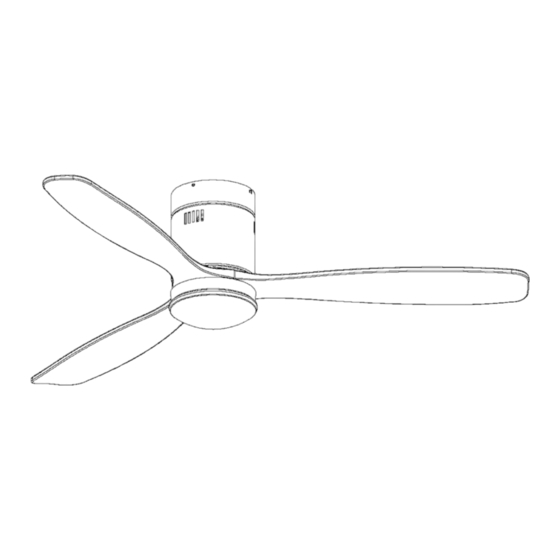
SIROCO
VENTILADOR DE TECHO DIMABLE
DIMMABLE CEILING FAN
329514D
(ES) GUÍA DE INSTALACIÓN · p 2
(EN) INSTALLATION GUIDE · p 9
Para ver la ficha técnica de producto completa, puede usar el siguiente código QR:
Para cualquier duda técnica pongase en contacto con nuestro Departamento Técnico.
Estamos a su servicio en nuestro email
irodriguez@schuller.es
o en nuestro teléfono 961 601 051 Ext. 229
Rev.10.23
1
Advertisement
Table of Contents

Related Manuals for Schuller 329514D


Summary of Contents for Schuller 329514D
- Page 1 SIROCO VENTILADOR DE TECHO DIMABLE DIMMABLE CEILING FAN 329514D (ES) GUÍA DE INSTALACIÓN · p 2 (EN) INSTALLATION GUIDE · p 9 Para ver la ficha técnica de producto completa, puede usar el siguiente código QR: Para cualquier duda técnica pongase en contacto con nuestro Departamento Técnico.
-
Page 2: Recomendaciones De Seguridad
LISTADO DE COMPONENTES INCLUIDOS. Cuerpo (motor ventilador) Aspas (3 uds) Módulo de control y mando y soporte a techo Placa Led Difusor de cristal Pack herrajes instalación Abra con cuidado el embalaje. Retire los elementos de las inserciones de espuma de poliestireno. Retire la carcasa del motor y colóquela sobre una alfombra o espuma de poliestireno para evitar dañar el acabado. -
Page 3: Guia De Instalación
GUIA DE INSTALACIÓN Preparación de la instalación: Para evitar lesiones personales y daños, asegúrese de que la ubicación para colgar permita 2,3 metros libre desde suelo hasta las aspas y 76cm libres en la horizontal desde cualquier pared o elemento constructivo. - Page 4 Montaje de los componentes del ventilador: 1- Conexión de módulo y fijación a techo del ventilador. 1- Conectar el módulo de control al ventilador: Conecte los cables del ventilador siguiendo la guía de color y números indicados en el módulo. 2-Conectar los cables de corriente a la regleta.
- Page 5 4.- Conectar los cables al receptor Toma de tierra Toma de corriente Toma de iluminación Toma de motor 5.- Fijar el ventilador al soporte del techo...
- Page 6 2- Montaje de las Aspas Atornillar las aspas de madera utilizando los tornillos y arandelas proporcionados. 3- Montaje de la placa iluminación. Para montar el plafón metálico fijándolo bajo las aspas. 1.-Desenroscar los tornillos 2.- Conectar la placa iluminación led a los cables que salen del motor mediante la ficha de conexión rápida.
- Page 7 NOTAS DE FUNCIONAMIENTO: 1. Las primeras 24 horas tras la instalación es normal apreciar un ligero rumor durante el funcionamiento del ventilador. Tras ese periodo de ajuste el rumor desaparecerá. La luz del ventilador apagada a través del mando a distancia queda en stand-by. Quedará completamente apagada, si se corta la corriente a través del interruptor de pared Si realiza la instalación en un falso techo de escayola, madera o metal es posible que se amplifique el rumor del ventilador debido a la cámara de aire existente.
- Page 8 SOLUCIONES A PROBLEMAS DE FUNCIONAMIENTO 1 No giran las aspas, no se enciende la luz o alguna de ellas. Comprobar que las conexiones de instalación rápida han quedado bien sujetas hasta su posición final. (Puede que se desconecten en el momento de la colocación definitiva por la gran cantidad de cables que se manejan a la vez) 2 Ruidos, roces, zumbidos, golpes cíclicos etc.
- Page 9 SIROCO DIMABLE CEILING FAN 329514D INSTALLATION GUIDE You may use the following QR code to view the complete technical data sheet of the product: If you have any technical questions, please do not hesitate to contact our technical Department. We are at your disposal in our email: irodriguez@schuller.es...
-
Page 10: Safety Recommendations
LIST OF INCLUDED COMPONENTS Control module and remote control Fan body (Fan motor) Blades (3 uds) LED board Light diffusor Installation hardware pack Carefully open the packaging. Remove the elements from the Styrofoam inserts. Remove the motor housing and place it on a carpet or on some Styrofoam to avoid damaging the finish. Note: Check the parts inventory to ensure that all parts have been included before commencing installation. -
Page 11: Installation Preparation
INSTALLATION GUIDE Installation preparation: To avoid personal injury and damage, ensure that the hanging position allows for at least 2.3 meters between the floor and the blades and that there is at least 76cm of horizontal distance between the fan and any wall or other obstruction. - Page 12 Assembling the fan components: 1- Connecting the control module and fixing fan to the ceiling. 1 - Connect the control module to the fan. Connect the cables using the quick connect tabs. 2 - Connect the power cables to the terminal strip connector. 3 - Hang the fan on the hook of the bracket to the ceiling support.
- Page 13 4 - Conect the fan cables to the module Ground wire Remote control imput wires Lamp imput wires Fan motor´s imput wires Fix the fan to the ceiling support...
- Page 14 2 - Assembling the blades Install the wooden blades, using the screws provided. 3 - Fitting the ceiling light. Fit the metal light ring by fixing it in place under the blades 1.-Remove the screws 2.- Connect the led lighting board to the cables coming out of the motor through the quick connection tab.
- Page 15 REMARKS: The first 24 hours after installation, it is normal to notice a slight noise during fan operation. After this adjustment period, the rumor will disappear. 2. The light of the fan turned off through the remote control remains in stand-by mode. It will be completely off if power is cut off through the wall switch.
- Page 16 POSIBLE SOLUTIONS TO OPERATIONAL PROBLEMS 1. The blades do not rotate, the light or some of them do not turn on. Check that the quick installation connections have been securely fastened until their final position. (They may be disconnected at the time of final placement due to the large number of cables that are handled at the same time) 2.
Need help?
Do you have a question about the 329514D and is the answer not in the manual?
Questions and answers