Advertisement
Quick Links
Advertisement

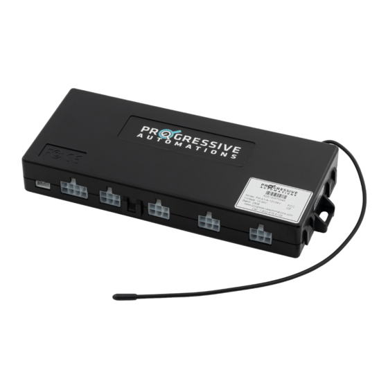
Summary of Contents for progressive automations PA-41-4-12V24V
- Page 1 PA-41-4-12V24V User Manual Scan for more information...
- Page 2 Table of Contents Specifications Wiring Diagram Dimensional Drawing Operation Have any queries? Our expert engineers are here to help! sales@progressiveautomations.com progressiveautomations.com 1-800-676-6123 P a g e | 2...
- Page 3 Specifications Number of Channels 1-4 Matching Actuators Input Voltage 12-24 VDC Output Voltage 12-24 VDC Max Current at 12VDC Per Channel 6.25 A Max Current at 24VDC Per Channel Duty Cycle 10% (2 min on, 18 min off) Feedback Input Hall Effect Sensor Operational Temperature -30°C to 60°C...
- Page 4 Wiring Diagram P a g e | 4...
- Page 5 Dimensional Drawing P a g e | 5...
- Page 6 Operation FIRST-TIME SETUP • Plug the compatible actuators into the control box ports. Do not install these actuators yet into the application. • Attach the stripped side of the power harness to the power supply. Red (+) for positive voltage, and Black (-) for neutral.
- Page 7 5. Once the actuators have fully retracted, a single beep should be heard from the control box to confirm the reset was successful. Resume normal use of the actuators. If no single beep was heard, disconnect the power from the control box and contact Progressive Automations directly for further troubleshooting.
- Page 8 Release the rocker after the actuators start moving. 4. Allow the actuators to fully retract, extend, and then retract again. Ensure that all actuators are moving. If any actuator is not moving and all connections are verified, contact Progressive Automations directly for further troubleshooting.


Need help?
Do you have a question about the PA-41-4-12V24V and is the answer not in the manual?
Questions and answers