Table of Contents

Related Manuals for Sun Microsystems N2000 Series


Summary of Contents for Sun Microsystems N2000 Series
- Page 1 N2000 Series Release 2.0— ™ Hardware Installation and Startup Guide Sun Microsystems, Inc. www.sun.com Part No. 817-7638-10 October 2004, Revision A Submit comments about this document at: http://www.sun.com/hwdocs/feedback...
- Page 2 Copyright 2004 Sun Microsystems, Inc., 4150 Network Circle, Santa Clara, Californie 95054, Etats-Unis. Tous droits réservés. Sun Microsystems, Inc. a les droits de propriété intellectuels relatants à la technologie qui est décrit dans ce document. En particulier, et sans la limitation, ces droits de propriété...
- Page 3 Operation of this equipment in a residential area is likely to cause harmful interference, in which case the user will be required to correct the interference at his own expense. Modifications: Any modifications made to this device that are not approved by Sun Microsystems, Inc. may void the authority granted to the user by the FCC to operate this equipment.
- Page 4 ICES-003 Class B Notice - Avis NMB-003, Classe B This Class B digital apparatus complies with Canadian ICES-003. Cet appareil numérique de la classe B est conforme à la norme NMB-003 du Canada. Sun N2000 Series Release 2.0 Hardware Installation and Startup Guide • October 2004...
- Page 5 BSMI Class A Notice The following statement is applicable to products shipped to Taiwan and marked as Class A on the product compliance label. CCC Class A Notice The following statement is applicable to products shipped to China and marked with “Class A” on the product’s compliance label.
- Page 6 Sun N2000 Series Release 2.0 Hardware Installation and Startup Guide • October 2004...
-
Page 7: Table Of Contents
Third-party Web sites ..................xv Contacting Sun technical support................ xvi Sun welcomes your comments ................xvi Abbreviations and acronyms ................xvi Chapter 1. N2000 Series hardware overview Introduction ......................1-1 Topics ......................1-1 N2000 Series hardware overview ..............1-2 N2000 Series chassis views ................1-3 Figure 1-1. - Page 8 Unpacking the N2000 Series ................2-2 Installation site requirements ................2-3 Table 2-1. N2000 Series physical and environmental requirements ..2-3 Mounting the N2000 Series into a rack ............. 2-4 Rackmounting requirements and specifications .......... 2-4 Table 2-2. Rackmounting requirements ..........2-4 Attaching the rackmounting hardware ............
- Page 9 2-post rack installation steps for flush mount ..........2-10 Figure 2-6. Securing the N2000 Series chassis to a 2-post rack (flush mount) 2-11 2-post rack installation steps for mid-position mount .........2-12 Figure 2-7. Securing the N2000 Series chassis to a 2-post rack (mid-position) 2-13 4-post rack installation steps ..............2-14...
- Page 10 Assigning the management IP address ............4-3 Chapter 5. System maintenance Introduction ....................... 5-1 Topics ......................5-1 Maintenance tasks for the N2000 Series ............5-2 Installing and replacing fiber-optic transceivers ..........5-2 Figure 5-1. Sample fiber-optic transceiver views ........5-3 Performing general maintenance ..............
-
Page 11: Preface
Sockets Layer (SSL) acceleration with reencryption and advanced Layer 4 to Layer 7 (L4 to L7) load balancing. The Sun N2000 Series system provides these services on a flexible, virtualized basis, within the convenience of a single enclosure, and with industry-leading speed, security, and availability. -
Page 12: What Is In This Manual
Performing system startup Chapter 4 System maintenance Chapter 5 Technical specifications Appendix A Related documentation For complete information about the Sun N2000 Series system, see the following documents. Title Document Number Location Sun N2000 Release 2.0 — 817-7641-10 Documentation CD Introduction Guide Sun N2000 Series Release 2.0 —... -
Page 13: Conventions
Contents xiii Conventions Typographical conventions This manual uses the following typographical conventions. Convention Function Example Ctrl+x Indicates a control key combination. Press Ctrl+C [key name] Identifies the name of a key to press. Type xyz, then press [Enter] brackets [ ] Indicates an optional argument. -
Page 14: Ip Addresses
Hardware Installation and Startup Guide IP addresses Use 4-byte dotted decimal notation, also called dot address or dotted quad address notation: . You can omit leading 0s in a byte position. 192.168.12.34 Subnet masks and wildcard masks Use 4-byte dotted decimal notation: (1s in bit positions to match, 255.255.255.0 0s in bit positions to ignore). -
Page 15: Notes, Cautions, Warnings
Contents Notes, cautions, warnings This manual uses the following formats to highlight notes, cautions, and warnings. Note: Pay special attention to the described feature or operation. Caution: Damage to hardware, software, or data is possible. Warning: Personal injury to yourself or others is possible. Accessing Sun documentation You can view, print, or purchase a broad selection of Sun documentation, including localized versions, at:... -
Page 16: Contacting Sun Technical Support
Certificate Authority client address translation Certificate and Key Manager command-line interface Certificate Signing Request Distinguished Encoding Rules format, ASN.1 Digital Signature Algorithm data terminal equipment ethMgmt.1 Ethernet management port on the N2000 Series FQDN fully qualified domain name Release V2.0... - Page 17 Message Digest 5 management information base N2000 Series Sun N2000 Series application switch N2040 N2000 Series model that provides 40 10/100-Mbps ports and 4 SFF pluggable Gibabit Ethernet ports N2120 N2000 Series model that provides 12 SFF pluggable Gigabit Ethernet ports...
- Page 18 User Security Model (SNMPv3) coordinated universal time virtual IP address VLAN virtual LAN virtual private network vRouter virtual router on the N2000 Series VRRP Virtual Router Redundancy Protocol VSRP Virtual Service Redundancy Protocol vSwitch virtual switch on the N2000 Series...
-
Page 19: Chapter 1. N2000 Series Hardware Overview
Chapter 1. N2000 Series hardware overview Introduction This chapter provides a high-level overview of the Sun N2000 Series application switch, as well as information that you should know before installing the hardware. Topics This chapter covers the following topics: Topic... -
Page 20: N2000 Series Hardware Overview
Web servers free to perform other network and application switching tasks. The N2000 Series is available in two versions: the N2120 and the N2040. The Sun N2120 platform provides 12 small form factor (SFF) pluggable Gigabit Ethernet ports. -
Page 21: N2000 Series Chassis Views
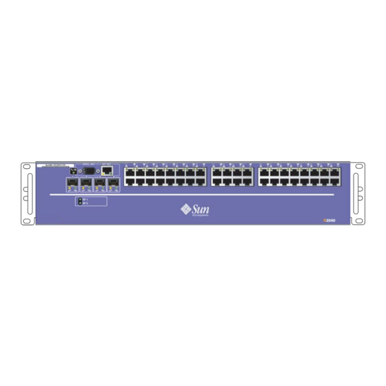
N2000 Series hardware overview N2000 Series chassis views N2000 Series chassis views Figure 1-1 illustrates the N2120 system, and Figure 1-2 illustrates the N2040 system. Figure 1-1. Sun N2120 chassis Front view Rea r view Install_1 Figure 1-2. Sun N2040 chassis... -
Page 22: External Network And Management Connections
Hardware Installation and Startup Guide External network and management connections External network and management connections Ethernet ports Ethernet 10/100BASE-T ports require standard unshielded twisted-pair/shielded twisted-pair (UTP/STP) network cable, Category 5 or 5E, with RJ-45 8-pin modular connectors. Gigabit Ethernet ports require SFF pluggable LC or MT-RJ fiber-optic connectors on multimode fiber-optic cable. -
Page 23: System Board
The system contains seven fans to ensure adequate airflow. As you look at an N2000 Series system from the front, the fans are on the left side and intake vents are on the right. The fans exhaust to the left. Allow at least 3 inches (7.6 cm) of unobstructed space on both sides. -
Page 24: System Power Supply
System LEDs System power supply The Sun N2000 Series system includes two 600W power supplies. Each power supply uses a separate power cord that you connect to the power source. If a failure occurs in the redundant power configuration, the N2000 sends an event message to the system log file to notify you that one of the power supplies is out of service. -
Page 25: System Software And Storage
System function card not booting up or error System software and storage The system software is loaded on the N2000 Series internal flash disk when shipped from Sun. When released by Sun, software upgrades are available on a software distribution CD-ROM. Software can then be downloaded or copied from a PC using Telnet, TFTP, or other file transfer mechanism. -
Page 26: System Management
Web interface The Sun Application Switch Manager Web interface is a graphical user interface (GUI) that allows you to configure and manage the N2000 Series using popular Web browsers. The Web interface supports all management capabilities provided by the CLI. Instead of entering information on a command line, you navigate menus and supply information in menu fields. -
Page 27: Snmp
SNMP The Simple Network Management Protocol (SNMP) allows you to communicate with the SNMP agent on the N2000 Series system from a remote management station. This allows you to retrieve information about managed objects on the system as well as change configuration settings. -
Page 29: Chapter 2. Installing The Chassis
Chapter 2. Installing the chassis Introduction This chapter describes the Sun N2000 Series chassis installation. Topics This chapter covers the following topics: Topic Page Required tools Unpacking the N2000 Series Installation site requirements Mounting the N2000 Series into a rack... -
Page 30: Required Tools
Refer to the Sun N2000 Series 2.0 — Release Notes for the latest information about the contents of the shipping container. If any of the listed components are missing, contact Sun Microsystems or your distributor/reseller. -
Page 31: Installation Site Requirements
Installing the chassis Installation site requirements Installation site requirements Before installing the chassis, ensure that your installation site meets the physical and environmental requirements for the N2000 Series as listed in Table 2-1. (See Table A-1 Table A-2 for a complete list of hardware specifications.) Table 2-1. -
Page 32: Mounting The N2000 Series Into A Rack
The rackmounting hardware includes mounting flanges, screws, and brackets for front and rear chassis mounting to accommodate 2-post and 4-post racks. Rackmounting requirements and specifications Before installing the N2000 Series chassis into a computer rack, refer to Table 2-2 the physical requirements associated with a rack installation. -
Page 33: Attaching The Rackmounting Hardware
Important: Failure to use the supplied screws could result in damage to the hardware. Attach the right mounting flange to the N2000 Series system by lining up the flange holes with screw holes on the side of the chassis. Using the No. 2 Phillips screwdriver, secure the flange to the chassis using four screws. - Page 34 Hardware Installation and Startup Guide Mounting the N2000 Series into a rack Figure 2-2. Attaching the rackmounting flanges (front) Install_4 Release V2.0...
- Page 35 Install_16b Figure 2-4 illustrates how to attach the mounting support brackets to the rear posts. Note: Rack-specific mounting screws, nuts, and miscellaneous hardware items are not included with the N2000 Series system due to the many variations available. Release V2.0...
-
Page 36: Positioning And Securing The Chassis
Hardware Installation and Startup Guide Mounting the N2000 Series into a rack Figure 2-4. Attaching the mounting support brackets (rear Install_23 Positioning and securing the chassis To complete the chassis installation in a rack, locate the following: • 10-32 mounting screws •... - Page 37 Installing the chassis Mounting the N2000 Series into a rack Figure 2-5. Rack hole spacing (in inches) and hole selection .50 in. .625 in. Split this pairing for correct hole alignment. Install_22 Release V2.0...
-
Page 38: 2-Post Rack Installation Steps For Flush Mount
Hardware Installation and Startup Guide 2-10 Mounting the N2000 Series into a rack 2-post rack installation steps for flush mount Perform the following steps to install the chassis into a 2-post rack (Figure 2-6): Step Action Using two persons, move the chassis up or down in the rack to align the hole positions on the mounting flanges with the corresponding mounting holes on the vertical supports. - Page 39 Installing the chassis 2-11 Mounting the N2000 Series into a rack Figure 2-6. Securing the N2000 Series chassis to a 2-post rack (flush mount) Install_6 Release V2.0...
-
Page 40: 2-Post Rack Installation Steps For Mid-Position Mount
Hardware Installation and Startup Guide 2-12 Mounting the N2000 Series into a rack 2-post rack installation steps for mid-position mount Perform the following steps to install the chassis into a 2-post rack using the optional mid-position mounting hardware (Figure 2-7):... - Page 41 Installing the chassis 2-13 Mounting the N2000 Series into a rack Figure 2-7. Securing the N2000 Series chassis to a 2-post rack (mid-position) 2-post rack Mid-position mounting sheet metal brackets (2) Rear Threaded holes Front 10/32 Phillips #2 screws (use 2 or 4 screws per flange) Install_25 Release V2.0...
-
Page 42: 4-Post Rack Installation Steps
Install and tighten the screw that secures the rear rail to the installed mount on the rack (Figure 2-8). Repeat this step for the opposite rail. Figure 2-8. Securing the N2000 Series chassis to a 4-post rack Install_24 Release V2.0... -
Page 43: Installing The N2000 Series On A Flat Surface
Installing the N2000 Series on a flat surface Installing the N2000 Series on a flat surface If you are installing the N2000 Series system on a smooth tabletop or flat surface, attach the four sticky-back rubber cushions to the bottom of the chassis. The cushions prevent the system from sliding and falling to the floor. - Page 44 Hardware Installation and Startup Guide 2-16 Installing the N2000 Series on a flat surface Release V2.0...
-
Page 45: Chapter 3. Installing System And Network Cables
Chapter 3. Installing system and network cables Introduction This chapter covers the Sun N2000 Series system and network cable installation procedures. Topics This chapter includes the following topics: Topic Page Required tools Connecting AC power to the chassis AC power requirements... -
Page 46: Required Tools
The only tool required for installing network and console cabling is a 1/4-inch (0.64-cm) flat blade screwdriver (for securing cable interface connectors). Connecting AC power to the chassis This section shows you how to connect the system power cable to the N2000 Series system.The system uses two power supplies. Figure 3-1 illustrates the N2000 Series redundant power supply configuration. -
Page 47: Ac Power Requirements
Installing system and network cables Connecting AC power to the chassis AC power requirements Before installing the power cords, ensure that your site is compatible with the N2000 Series AC power requirements: • Voltage: 115 or 230 VAC (90 to 135 or 180 to 265 VAC), 60 Hz (47 to 63 Hz); automatic selection •... - Page 48 Hardware Installation and Startup Guide Connecting AC power to the chassis Note: If you want to view the system startup sequence, attach a system console prior to applying power. See “Connecting to the console port” on page 3-5. Figure 3-2. Attaching the power cords 15A receptacle (North America) or compatible power source...
-
Page 49: Connecting To The Console Port
This section shows you how to connect a video display terminal or PC to the N2000 Series console port. The console port provides a serial RS-232 connection with a DTE interface using a male DB-9 connector. Attaching a terminal or PC allows you to connect to the system CLI for initial setup at the installation site. - Page 50 Parity: none • Flow control: none If the N2000 Series is powered on, press the [Enter] key at the keyboard to display the user name prompt that allows you to access the system CLI. Refer to Chapter 4, “Performing system startup”...
-
Page 51: Connecting To The Management Port
SF 1 SF 2 Laptop computer Install_7 Connecting to the management port The N2000 Series management port allows you to access the CLI over a Telnet connection, or to access the Sun Application Switch Manager from your Web browser. Release V2.0... - Page 52 Hardware Installation and Startup Guide Connecting to the management port To connect to the management port, you need the following: • For connection to an Ethernet hub or switch, an RJ-45 to RJ-45 straight-through cable (100 ohm, Category 5 or 5E, maximum length/328 feet/100 meters) •...
- Page 53 Installing system and network cables Connecting to the management port Step Action Connect the other end of the cable to an available port on the Ethernet hub or switch. The LEDs should display green (Link) and yellow (Activity). If connecting a PC or laptop computer directly to the MGMT 10/100 port, use an Ethernet crossover cable or crossover adapter to ensure a proper connection to the port.
-
Page 54: Connecting A Local Modem
Connecting a local modem Connecting a local modem The N2000 Series supports asynchronous transmission over modems for remote access to the system console port and CLI. With most external modems (such as AT or Hayes-compatible), use a customer-supplied DB-9 to DB-25 modem cable. -
Page 55: Connecting The Network Cables
Installing system and network cables 3-11 Connecting the network cables To connect a modem to the N2000 Series, perform the following steps(Figure 3-7): Step Action Turn on the modem, then refer to the documentation supplied with the modem to configure the modem with the following settings: •... -
Page 56: Connecting To The Ethernet Ports
Hardware Installation and Startup Guide 3-12 Connecting the network cables Connecting to the Ethernet ports To connect the 10/100-Mbps Ethernet ports to the external data network, you need the following components: • An RJ-45 to RJ-45 straight-through cable (100 ohm, Category 5 or 5E, with a maximum length of 328 feet/100 meters) •... - Page 57 Connect the other end to an Ethernet link to the external data network. Check the LEDs. They should display green (Link) and yellow (Activity). Figure 3-8. N2000 Series Ethernet connections Gigabit Ethernet (fiber optic) LC or MT-RJ style connectors Ethernet 10/100 (RJ-45)
-
Page 59: Chapter 4. Performing System Startup
Chapter 4. Performing system startup Introduction This chapter describes how to power up the N2000 Series system, as well as initially configure the system to be a host-only device that you can ping on a network. Topics This chapter contains the following topics:... -
Page 60: Checking The System Leds
Hardware Installation and Startup Guide Checking the system LEDs Checking the system LEDs After powering on the system, check the system LEDs to ensure proper cabling and connections. Table 4-1 lists and describes the LEDs that are available on the N2120 and N2040 systems. -
Page 61: Logging On And Starting The Cli
Assigning the management IP address This section describes how to configure the N2000 Series system on the network as a host-only node that can be “pinged” by other devices on the network. As a host, the N2000 Series will respond to network... - Page 62 • are customer-supplied IP network settings. ip-address networkMask For detailed information on configuring the N2000 Series, refer to the following manuals: • Sun N2000 Series Release 2.0 – System Configuration Guide • Sun N2000 Series Release 2.0 – Command Reference...
-
Page 63: Chapter 5. System Maintenance
This chapter covers N2000 Series maintenance. Caution: Only qualified Sun-trained personnel are authorized to perform maintenance tasks associated with the N2000 Series internal hardware. These tasks require that the system be removed from the equipment rack and placed top-side down on a bench or tabletop for proper removal of the system sheet metal cover and access to system modules and components. -
Page 64: Maintenance Tasks For The N2000 Series
Hardware Installation and Startup Guide Maintenance tasks for the N2000 Series Maintenance tasks for the N2000 Series The following N2000 Series maintenance tasks are to be performed by qualified Sun personnel: • Removing the chassis sheet metal cover • Installing a Service Load Balancing with SSL Function Card... - Page 65 System maintenance Installing and replacing fiber-optic transceivers Figure 5-1. Sample fiber-optic transceiver views Top view Extractor bail Side view Front view Bottom view Perform the following steps to install and remove the transceiver: Step Action To install: With the tapered end of the transceiver pointed toward the interface, slide the transceiver into the connector until it snaps into place.
-
Page 66: Performing General Maintenance
Hardware Installation and Startup Guide Performing general maintenance Performing general maintenance Vacuum the chassis air intake vents, as well as areas around the chassis as necessary to keep dust and particles from entering the chassis. While dust is not an immediate danger to the system hardware, dust can retain moisture that could eventually damage electronic components. -
Page 67: Appendix A. Technical Specifications
Appendix A. Technical specifications N2000 Series hardware Table A-1. N2000 Series hardware technical specifications Description Specification N2000 Series chassis (2RU enclosure) • Height: 3.5 in. (8.89 cm) • Depth: 26 in. (66.04 cm) • Width: 17.4 in. (44.19 cm) •... -
Page 68: N2000 Series Hardware
Hardware Installation and Startup Guide N2000 Series hardware Table A-1. N2000 Series hardware technical specifications (continued) Description Specification Maximum heat dissipation, fully populated 2050 BTU/hr Management port Single 10/100-Mbps Ethernet port with RJ-45 receptacle; requires a standard UTP/STP network cable, Category 5 or 5E, with an RJ-45 8-pin modular connector. -
Page 69: Cautions And Dangers
Technical specifications Cautions and dangers Cautions and dangers Caution: Do not insert an RJ-11 telephone connector into the Ethernet management port or any Ethernet port on the system. Damage to the port may occur. Danger: When handling Class 1 laser devices and cables, DO NOT look directly into the connector or laser light source, as this could cause serious eye injury or blindness. -
Page 70: N2000 Series Rack Mounting
Hardware Installation and Startup Guide N2000 Series rack mounting N2000 Series rack mounting Table A-2. N2000 Series rack mounting specifications Description Specification Rack size Width of 19 in. (48.26 cm), depth of 30 to 36 in. (76.2 to 91.44 cm); 2-post or 4-post ( 4-post is... -
Page 71: Shock And Vibration
Technical specifications N2000 Series certifications and compliance Shock and Vibration ISTA Specification 1A (product packaging for shipment) Safety UL 1950 IEC60950 CSA-C22.2 EN 60950 TUV GS Release V2.0... -
Page 73: Index
N2000 Series operating ambient air temperature heat dissipation certifications and compliance chassis installation immunity in a rack installation... - Page 74 3-11 two-post installation procedure (mid-mount) 2-12 modems,connecting local 3-10 redundant power relative humidity RS-232 serial port See console port N2000 Series certifications and compliance chassis views cooling requirements environmental requirements safety function cards shock and vibration LEDs SNMP support...
Need help?
Do you have a question about the N2000 Series and is the answer not in the manual?
Questions and answers