Table of Contents

Related Manuals for MG M3-UNIT Series


Summary of Contents for MG M3-UNIT Series
- Page 1 Space-saving Signal Conditioners M3-UNIT Series SIGNAL TRANSMITTER (field- and PC-configurable) Model: M3LV OPERATING MANUAL MG CO., LTD. www.mgco.jp M3LV EM-2660-B Rev.5 5-2-55 Minamitsumori, Nishinari-ku, Osaka 557-0063 JAPAN...
-
Page 2: Table Of Contents
8.1 CAUTION IN WIRING ......................18 8.2 WIRING INSTRUCTIONS ....................18 8.3 TERMINAL ASSIGNMENT ....................20 8.4 TERMINAL CONNECTIONS ....................21 8.4.1 WIRING INPUT.......................21 8.4.2 WIRING OUTPUT....................21 8.4.3 WIRING POWER ....................22 MG CO., LTD. www.mgco.jp M3LV EM-2660-B Rev.5 5-2-55 Minamitsumori, Nishinari-ku, Osaka 557-0063 JAPAN... - Page 3 12.1.5 PERFORMANCE ....................36 12.1.6 STANDARDS & APPROVALS ................36 12.1.7 CALCULATION EXAMPLES OF OVERALL ACCURACY ........36 12.2 PC CONFIGURATOR SOFTWARE ..................37 12.3 MODEL NUMBERING ......................38 12.4 EXTERNAL DIMENSIONS ....................39 MG CO., LTD. www.mgco.jp M3LV EM-2660-B Rev.5 5-2-55 Minamitsumori, Nishinari-ku, Osaka 557-0063 JAPAN...
-
Page 4: Introduction
Thank you for your choosing us. Read this manual carefully to ensure that you use the product correctly and safely. 1.1 PACKAGE Check contents of the package you received as outlined below. • Signal conditioner • Accessories I/O range and tag name label sheet Instruction manual MG CO., LTD. www.mgco.jp M3LV EM-2660-B Rev.5 5-2-55 Minamitsumori, Nishinari-ku, Osaka 557-0063 JAPAN... -
Page 5: Safety Precautions (That Must Be Observed)
Do not throw the unit into the fire. • Doing so may result in electric shock. • Doing so may result in rupture of the electronic component. PROHIBITION WET HANDS MG CO., LTD. www.mgco.jp M3LV EM-2660-B Rev.5 5-2-55 Minamitsumori, Nishinari-ku, Osaka 557-0063 JAPAN... - Page 6 • Doing so may result in malfunction of the unit. Use a minus screwdriver and tweezers in setting the switches. • Failure to do so may result in malfunction of the unit. MG CO., LTD. www.mgco.jp M3LV EM-2660-B Rev.5 5-2-55 Minamitsumori, Nishinari-ku, Osaka 557-0063 JAPAN...
-
Page 7: Points Of Caution
– Where the unit is exposed to direct sunlight, rain or wind. (The unit is not designed for outdoor use.) – Where condensation may occur due to extreme temperature changes. MG CO., LTD. www.mgco.jp M3LV EM-2660-B Rev.5 5-2-55 Minamitsumori, Nishinari-ku, Osaka 557-0063 JAPAN... -
Page 8: Wiring
• When abnormality is found such like smokes, unusual smell and abnormal noises coming from the unit, immediately cut the power supply and stop using it. MG CO., LTD. www.mgco.jp M3LV EM-2660-B Rev.5 5-2-55 Minamitsumori, Nishinari-ku, Osaka 557-0063 JAPAN... -
Page 9: Features And Preparation Procedure Of M3Lv
• With front control buttons and a simulator. • Using the PC Con gurator Software (model: M3LVCFG). OUTPUT RANGING • With front control buttons, a simulator and a multimeter. STARTING OPERATION MG CO., LTD. www.mgco.jp M3LV EM-2660-B Rev.5 5-2-55 Minamitsumori, Nishinari-ku, Osaka 557-0063 JAPAN... -
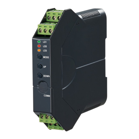
Page 10: Component Identification
(9) Tag name label When a tag No. is specified, the unit(s) will be shipped with the tag name label put on the above position. MG CO., LTD. www.mgco.jp M3LV EM-2660-B Rev.5 5-2-55 Minamitsumori, Nishinari-ku, Osaka 557-0063 JAPAN... -
Page 11: Status Indicator Led
The output is below -15% or above 115%. Check the setting and input. DIP SW error DIP SW configuration is inappropriate. Check the SW settings. System error Indicates the CPU’s communication error. MG CO., LTD. www.mgco.jp M3LV EM-2660-B Rev.5 5-2-55 Minamitsumori, Nishinari-ku, Osaka 557-0063 JAPAN... - Page 12 Fine span adjustment NOTE In the I/O ranging and fine adjustments using the PC Configurator Software (model: M3LVCFG), the LEDs are not ac- cording to the above tables. MG CO., LTD. www.mgco.jp M3LV EM-2660-B Rev.5 5-2-55 Minamitsumori, Nishinari-ku, Osaka 557-0063 JAPAN...
-
Page 13: Internal View
5.2 INTERNAL VIEW (1) SW1 (2) SW2 (1) SW1 Sets output type. (2) SW2 Sets input type, output type, front control button lock and configuration mode. MG CO., LTD. www.mgco.jp M3LV EM-2660-B Rev.5 5-2-55 Minamitsumori, Nishinari-ku, Osaka 557-0063 JAPAN... -
Page 14: How To Open The Cover
• Be careful not to get your hand or finger caught in the cover. • Do not force the cover closed. Doing so may result in damage of the electronic components. MG CO., LTD. www.mgco.jp M3LV EM-2660-B Rev.5 5-2-55 Minamitsumori, Nishinari-ku, Osaka 557-0063 JAPAN... -
Page 15: Dip Switch Configuration
• Use a minus screwdriver with the blade edge 0.8 mm (0.03”) to set the DIP switches. • Do not touch other electronic components except for the DIP switches. MG CO., LTD. www.mgco.jp M3LV EM-2660-B Rev.5 5-2-55 Minamitsumori, Nishinari-ku, Osaka 557-0063 JAPAN... -
Page 16: Configuration Mode
• DC voltage output (narrow spans) [maximum range: -2.5 to +2.5 V DC] SW1-4 SW1-3 SW1-2 SW1-1 SW2-4 SW2-3 • DC voltage output (wide spans) [maximum range: -10 to +10 V DC] SW1-4 SW1-3 SW1-2 SW1-1 SW2-4 SW2-3 MG CO., LTD. www.mgco.jp M3LV EM-2660-B Rev.5 5-2-55 Minamitsumori, Nishinari-ku, Osaka 557-0063 JAPAN... -
Page 17: Front Control Button Lock
This function is applicable to the firmware 2.01 or higher version. Confirm the firmware version on the specification label on the side of the transmitter. LOCK SW2-1 Unlock Lock MG CO., LTD. www.mgco.jp M3LV EM-2660-B Rev.5 5-2-55 Minamitsumori, Nishinari-ku, Osaka 557-0063 JAPAN... -
Page 18: Wiring
1.0 to 1.5 mm AI-TWIN 2X 1,5-8 BK 0.75 to 1.0 mm AI 1,0-8 RD 1.0 to 1.5 mm AI 1,5-8 BK Recommended manufacturer: Phoenix Contact GmbH & Co., KG MG CO., LTD. www.mgco.jp M3LV EM-2660-B Rev.5 5-2-55 Minamitsumori, Nishinari-ku, Osaka 557-0063 JAPAN... - Page 19 Push the terminal block until it clicks into place. NOTE Match the terminal numbers of the terminal blocks with those indicated on the trans- mitter body in installing the blocks (figure on the right). MG CO., LTD. www.mgco.jp M3LV EM-2660-B Rev.5 5-2-55 Minamitsumori, Nishinari-ku, Osaka 557-0063 JAPAN...
-
Page 20: Terminal Assignment
Insert a wire into the dead end of a terminal block and fix it with a minus screwdriver with the blade edge 0.6 mm (0.02”) and the blade width 3.5 mm (0.14”) (torque: 0.5 – 0.6 N∙m). 8.3 TERMINAL ASSIGNMENT Power Output signal Input signal MG CO., LTD. www.mgco.jp M3LV EM-2660-B Rev.5 5-2-55 Minamitsumori, Nishinari-ku, Osaka 557-0063 JAPAN... -
Page 21: Terminal Connections
(resistance 100 ohms or less) 8.4.2 WIRING OUTPUT Voltage or current output is provided depending on the output setting. Output Output Ground (resistance 100 ohms or less) MG CO., LTD. www.mgco.jp M3LV EM-2660-B Rev.5 5-2-55 Minamitsumori, Nishinari-ku, Osaka 557-0063 JAPAN... -
Page 22: Wiring Power
CODE RATING ALLOWABLE RANGE & POWER CONSUMPTION 10 to 32 V DC 9 to 36 V DC, approx. 3 W DC power DC power Confirm the polarity. MG CO., LTD. www.mgco.jp M3LV EM-2660-B Rev.5 5-2-55 Minamitsumori, Nishinari-ku, Osaka 557-0063 JAPAN... -
Page 23: Installation
Spring Loaded DIN Rail Adaptor ■ REMOVAL Push down the DIN rail adaptor utilizing a minus screwdriver and pull. DIN Rail 35mm wide Spring Loaded DIN Rail Adaptor MG CO., LTD. www.mgco.jp M3LV EM-2660-B Rev.5 5-2-55 Minamitsumori, Nishinari-ku, Osaka 557-0063 JAPAN... -
Page 24: Calibration
When you release the button, the LD1 is returned to ON. Therefore hold down the button until the LD1 turns OFF. MG CO., LTD. www.mgco.jp M3LV EM-2660-B Rev.5 5-2-55 Minamitsumori, Nishinari-ku, Osaka 557-0063 JAPAN... -
Page 25: Input & Output Ranging
• There is no stated order of setting 0% and 100% levels or no limitations of entering values for multiple times within one step of Ranging Mode. • Signal level is not stored when UP or DOWN button is released before the LD1 turns OFF. MG CO., LTD. www.mgco.jp M3LV EM-2660-B Rev.5 5-2-55 Minamitsumori, Nishinari-ku, Osaka 557-0063 JAPAN... - Page 26 • There is no stated order of setting 0% and 100% levels or no limitations of entering values for multiple times within one step of the Ranging Mode. • Signal level is not stored when UP or DOWN button is released before the LD1 turns OFF. MG CO., LTD. www.mgco.jp M3LV EM-2660-B Rev.5 5-2-55 Minamitsumori, Nishinari-ku, Osaka 557-0063 JAPAN...
-
Page 27: Maximum Range, Minimum Span And Default Value Of Input
MINIMUM SPAN DEFAULT VALUE -10 to +10 V DC 1 to 5 V DC NOTE The ex-factory setting is 4 – 20 mA DC unless otherwise specified. MG CO., LTD. www.mgco.jp M3LV EM-2660-B Rev.5 5-2-55 Minamitsumori, Nishinari-ku, Osaka 557-0063 JAPAN... -
Page 28: Operation Procedure Of I/O Ranging
• The LD1 turning OFF means completion of 100% input ranging. Hold down UP button until the LD1 turns OFF. • Skip to the next procedure when 100% input ranging is not necessary. MG CO., LTD. www.mgco.jp M3LV EM-2660-B Rev.5... - Page 29 • The LD1 turning OFF means completion of 100% output ranging. Hold down UP button until the LD1 turns OFF. • Skip to the next procedure when 100% output ranging is not necessary. MG CO., LTD. www.mgco.jp M3LV EM-2660-B Rev.5...
- Page 30 • Hold down MODE button for approx. 2 sec. to return to the RUN mode. • The LD3 turns OFF and the LD1 green LED is ON (DIP SW configuration) or blinking (PC configuration). MG CO., LTD. www.mgco.jp M3LV EM-2660-B Rev.5...
-
Page 31: Fine Adjustment Mode
• Warm up measuring instruments, equipment and other devices on site for the time specified in each manual, and oper- ate the unit in a stable condition. • Adjustable ranges are as follows: Fine zero adjustment -15 to +15% Fine span adjustment 85 to 115% MG CO., LTD. www.mgco.jp M3LV EM-2660-B Rev.5 5-2-55 Minamitsumori, Nishinari-ku, Osaka 557-0063 JAPAN... -
Page 32: Operation Procedure Of Fine Adjustment
• Hold down MODE button for approx. 2 sec. to go on to the Fine Span Adjustment Mode. • The LD2 turns OFF and the LD3 green LED starts blinking indicating the Fine Span Adjustment Mode. MG CO., LTD. www.mgco.jp M3LV EM-2660-B Rev.5... - Page 33 • Hold down MODE button for approx. 2 sec. to return to the RUN Mode. • The LD3 turns OFF and the LD1 green LED is ON (DIP SW configuration) or blinking (PC configuration). MG CO., LTD. www.mgco.jp M3LV EM-2660-B Rev.5...
-
Page 34: Checking, Maintenance
Warm up the unit for 10 minutes or more, apply 0, 25, 50, 75 and 100% input to the unit, and make sure that the output is 0, 25, 50, 75 and 100% respectively within the prescribed accuracy. In case the output is deviated from the accuracy, perform the fine zero/span adjustment. MG CO., LTD. www.mgco.jp M3LV EM-2660-B Rev.5 5-2-55 Minamitsumori, Nishinari-ku, Osaka 557-0063 JAPAN... -
Page 35: Appendices
Conformance range: -11.5 – +11.5 V DC Offset: Lower range can be any specific value within the output range provided that the minimum span is maintained. Load resistance: Output drive 1 mA maximum MG CO., LTD. www.mgco.jp M3LV EM-2660-B Rev.5 5-2-55 Minamitsumori, Nishinari-ku, Osaka 557-0063 JAPAN... -
Page 36: Installation
(2) Input Range 4 – 20 mA DC, Output Range 4 – 20 mA DC Max. Input Range (20 mA) ÷ Span (16 mA) × 0.02% + Max. Output Range (20 mA) ÷ Span (16 mA) × 0.04% = 0.75% MG CO., LTD. www.mgco.jp M3LV EM-2660-B Rev.5... -
Page 37: Pc Configurator Software
‘One-Step Cal’ calibration (I/O ranging) and DAC trimming (fine adjustments) are configurable with the PC Configurator Software regardless of the configuration option code and configuration mode. ■ REMARKS For detailed information on the PC configuration, refer to the M3LVCFG users manual (EM-9197-J). MG CO., LTD. www.mgco.jp M3LV EM-2660-B Rev.5 5-2-55 Minamitsumori, Nishinari-ku, Osaka 557-0063 JAPAN... -
Page 38: Model Numbering
/Q: Option other than the above (specify the specification) SPECIFICATIONS OF OPTION: Q COATING (For the detail, refer to our web site.) /C01: Silicone coating /C02: Polyurethane coating /C03: Rubber coating (UL not available) MG CO., LTD. www.mgco.jp M3LV EM-2660-B Rev.5 5-2-55 Minamitsumori, Nishinari-ku, Osaka 557-0063 JAPAN... -
Page 39: External Dimensions
12.4 EXTERNAL DIMENSIONS mm (inch) 10 11 12 DIN RAIL 35mm wide 18 (.71) 110.5 (4.35) [5 (.20)] • When mounting, no extra space is needed between units. MG CO., LTD. www.mgco.jp M3LV EM-2660-B Rev.5 5-2-55 Minamitsumori, Nishinari-ku, Osaka 557-0063 JAPAN...
Need help?
Do you have a question about the M3-UNIT Series and is the answer not in the manual?
Questions and answers