Sign In
Upload
Manuals
Brands
MG Manuals
Transmitter
M3-UNIT Series
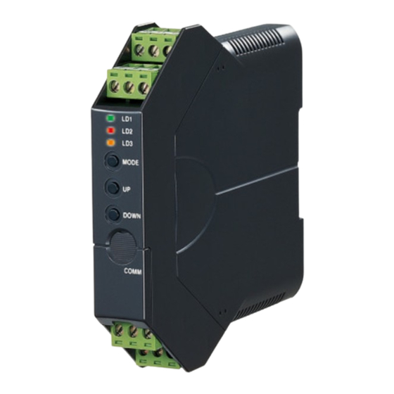
User Manuals: MG M3-UNIT Series Signal Transmitter
Manuals and User Guides for MG M3-UNIT Series Signal Transmitter. We have
3
MG M3-UNIT Series Signal Transmitter manuals available for free PDF download: Operating Manual
MG M3-UNIT Series Operating Manual (40 pages)
CURRENT LOOP SUPPLY
Brand:
MG
| Category:
Transmitter
| Size: 4 MB
Table of Contents
Table of Contents
2
1 Introduction
4
Package
4
2 SAFETY PRECAUTIONS (that Must be Observed)
5
3 Points of Caution
7
Before Use
7
Conformity with Ul
7
Conformity with Eu Directives
7
Environment
7
Wiring
8
Handling Cautions
8
4 Features and Preparation Procedure of M3Ldy
9
Features of M3Ldy
9
Preparation Procedure
9
5 Component Identification
10
Front and Side Views
10
Status Indicator Led
11
Internal View
13
6 How to Open the Cover
14
7 Dip Switch Configuration
15
Difference between Dip Sw Configuration and Pc Configuration
15
Dip Switch Selection Per I/O Specification
15
Configuration Mode
16
Input Type
16
Output Type
16
Front Control Button Lock
17
8 Wiring
18
Caution in Wiring
18
Wiring Instructions
18
Terminal Assignment
20
Terminal Connections
21
Wiring Input
21
Wiring Output
22
Wiring Power
22
9 Installation
23
10 Calibration
24
Calibration Flow
24
Input & Output Ranging
25
Outline of I/O Ranging
25
Maximum Range and Minimum Span of Input
27
Maximum Range, Minimum Span and Default Value of Output
27
Operation Procedure of I/O Ranging
28
Fine Adjustment Mode
31
Outline of Fine Adjustment
31
Operation Procedure of Fine Adjustment
32
11 Checking, Maintenance
34
Checking
34
Maintenance
34
12 Appendices
35
Specifications
35
General Specifications
35
Supply Output
35
Input Specifications
35
Output Specifications
35
Linearization (/A Only)
36
Installation
36
Performance
36
Standards & Approvals
36
Calculation Examples of Overall Accuracy
37
Pc Configurator Software
38
Model Numbering
39
External Dimensions
40
Advertisement
MG M3-UNIT Series Operating Manual (40 pages)
Space-saving Signal Conditioners RTD TRANSMITTER
Brand:
MG
| Category:
Transmitter
| Size: 4 MB
Table of Contents
Table of Contents
2
Introduction
4
Package
4
SAFETY PRECAUTIONS (that Must be Observed)
5
Points of Caution
7
Before Use
7
Conformity with Ul
7
Conformity with Eu Directives
7
Environment
7
Wiring
8
Handling Cautions
8
Features and Preparation Procedure of M3Lr
9
Features of M3Lr
9
Preparation Procedure
9
Component Identification
10
Front and Side Views
10
Status Indicator Led
11
Internal View
13
How to Open the Cover
14
Dip Switch Configuration
15
Difference between Dip Sw Configuration and Pc Configuration
15
Dip Switch Selection Per I/O Specification and Function
15
Configuration Mode
16
Input Type
16
Output Type
17
Front Control Button Lock
17
Wiring
18
Caution in Wiring
18
Wiring Instructions
18
Terminal Assignment
20
Terminal Connections
21
Wiring Input
21
Wiring Output
21
Wiring Power
22
Installation
23
Calibration
24
Calibration Flow
24
Input & Output Ranging
25
Outline of I/O Ranging
25
Maximum Range, Minimum Span and Default Value of Input
27
Maximum Range, Minimum Span and Default Value of Output
27
Operation Procedure of I/O Ranging
28
Fine Adjustment Mode
31
Outline of Fine Adjustment
31
Operation Procedure of Fine Adjustment
32
Checking, Maintenance
34
Checking
34
Maintenance
34
Appendices
35
Specifications
35
General Specifications
35
Input Specifications
35
Output Specifications
35
Installation
36
Performance
36
Standards & Approvals
36
I/O Type, Maximum Range & Accuracy
36
Calculation Examples of Overall Accuracy
37
Pc Configurator Software
38
Model Numbering
39
External Dimensions
40
MG M3-UNIT Series Operating Manual (39 pages)
SIGNAL TRANSMITTER
Brand:
MG
| Category:
Transmitter
| Size: 4 MB
Table of Contents
Table of Contents
2
Introduction
4
Package
4
SAFETY PRECAUTIONS (that Must be Observed)
5
Points of Caution
7
Before Use
7
Conformity with Ul
7
Conformity with Eu Directives
7
Environment
7
Wiring
8
Handling Cautions
8
Features and Preparation Procedure of M3Lv
9
Features of M3Lv
9
Preparation Procedure
9
Component Identification
10
Front and Side Views
10
Status Indicator Led
11
Internal View
13
How to Open the Cover
14
Dip Switch Configuration
15
Difference between Dip Sw Configuration and Pc Configuration
15
Dip Switch Selection Per I/O Specification
15
Configuration Mode
16
Input Type
16
Output Type
16
Front Control Button Lock
17
Wiring
18
Caution in Wiring
18
Wiring Instructions
18
Terminal Assignment
20
Terminal Connections
21
Wiring Input
21
Wiring Output
21
Wiring Power
22
Installation
23
Calibration
24
Calibration Flow
24
Input & Output Ranging
25
Outline of I/O Ranging
25
Maximum Range, Minimum Span and Default Value of Input
27
Maximum Range, Minimum Span and Default Value of Output
27
Operation Procedure of I/O Ranging
28
Fine Adjustment Mode
31
Outline of Fine Adjustment
31
Operation Procedure of Fine Adjustment
32
Checking, Maintenance
34
Checking
34
Maintenance
34
Appendices
35
Specifications
35
General Specifications
35
Input Specifications
35
Output Specifications
35
Installation
36
Performance
36
Standards & Approvals
36
Calculation Examples of Overall Accuracy
36
Pc Configurator Software
37
Model Numbering
38
External Dimensions
39
Advertisement
Advertisement
Related Products
MG M3LR
MG M3LV
MG Mini-M M2EXV
MG Mini-M M2EXS
MG M3LDY
MG Mini-M M2EXR
MG M3LT
MG MG3
MG Magnette KA
MG MGMLV480400
MG Categories
I/O Systems
Control Unit
Transmitter
Automobile
Measuring Instruments
More MG Manuals
Login
Sign In
OR
Sign in with Facebook
Sign in with Google
Upload manual
Upload from disk
Upload from URL