Table of Contents
Advertisement
Quick Links
INSTRUCTION MANUAL
SIGNAL TRANSMITTER
BEFORE USE ....
Thank you for choosing us. Before use, please check con-
tents of the package you received as outlined below.
If you have any problems or questions with the product,
please contact our sales office or representatives.
■ PACKAGE INCLUDES:
Signal transmitter ..............................................................(1)
■ MODEL NO.
Confirm Model No. marking on the product to be exactly
what you ordered.
■ INSTRUCTION MANUAL
This manual describes necessary points of caution when
you use this product, including installation, connection and
basic maintenance procedures.
POINTS OF CAUTION
■ CONFORMITY WITH EU DIRECTIVES
• The equipment must be mounted inside a panel.
• The actual installation environments such as panel con-
figurations, connected devices, connected wires, may af-
fect the protection level of this unit when it is integrated
in a panel system. The user may have to review the CE
requirements in regard to the whole system and employ
additional protective measures to ensure the CE conform-
ity.
• Install lightning surge protectors for those wires connect-
ed to remote locations.
■ POWER INPUT RATING & OPERATIONAL RANGE
• Locate the power input rating marked on the product and
confirm its operational range as indicated below:
24V DC rating: 24V ±10%, 0.6W max.
■ GENERAL PRECAUTIONS
• Before you remove the unit or mount it, turn off the power
supply and input signal for safety.
■ ENVIRONMENT
• Indoor use.
• When heavy dust or metal particles are present in the
air, install the unit inside proper housing with sufficient
ventilation.
• Do not install the unit where it is subjected to continuous
vibration. Do not subject the unit to physical impact.
• Environmental temperature must be within -20 to +55°C
(-4 to +131°F) with relative humidity within 30 to 90%
RH in order to ensure adequate life span and operation.
■ WIRING
• Do not install cables close to noise sources (relay drive
cable, high frequency line, etc.).
• Do not bind these cables together with those in which
noises are present. Do not install them in the same duct.
MG CO., LTD. www.mgco.jp
5-2-55 Minamitsumori, Nishinari-ku, Osaka 557-0063 JAPAN
(field-configurable)
MODEL
■ AND ....
• The unit is designed to function as soon as power is sup-
plied, however, a warm up for 10 minutes is required for
satisfying complete performance described in the data
sheet.
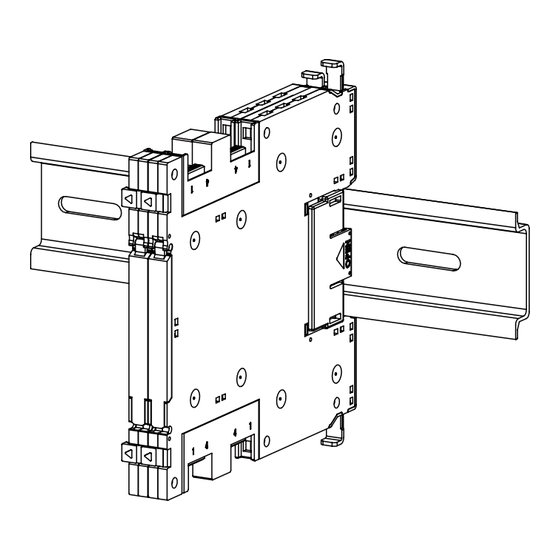
COMPONENT IDENTIFICATION
Body
Upper tab
Front cover
Lower tab
M60EVS
Upper slider
Power connector
Specifications
Lower slider
EM-8032 Rev.1 P. 1 / 6
Advertisement
Table of Contents

Related Manuals for MG M60EVS


Summary of Contents for MG M60EVS
- Page 1 • Do not bind these cables together with those in which noises are present. Do not install them in the same duct. EM-8032 Rev.1 P. 1 / 6 MG CO., LTD. www.mgco.jp 5-2-55 Minamitsumori, Nishinari-ku, Osaka 557-0063 JAPAN...
- Page 2 Confirm that the upper and lower tabs fit into the respec- tive concave portions of the already mounted unit. EM-8032 Rev.1 P. 2 / 6 MG CO., LTD. www.mgco.jp 5-2-55 Minamitsumori, Nishinari-ku, Osaka 557-0063 JAPAN...
- Page 3 2.1 [.08] 3.7 [.15] 2 [.08] 0.5 [.02] 6 [.24] 6 [.24] 102 [4.02] · With the end cover attached · Capable of High-density mounting EM-8032 Rev.1 P. 3 / 6 MG CO., LTD. www.mgco.jp 5-2-55 Minamitsumori, Nishinari-ku, Osaka 557-0063 JAPAN...
- Page 4 (AWG20) Outer sheth diameter: max 1.5 dia *1. The cable connector is not included in the package. Refer to the specifications of the product. EM-8032 Rev.1 P. 4 / 6 MG CO., LTD. www.mgco.jp 5-2-55 Minamitsumori, Nishinari-ku, Osaka 557-0063 JAPAN...
- Page 5 0 – 10 V 2 – 10 V 0 – 5 V 1 – 5 V • Response Time RESPONSE TIME SW2-4 Standard Response (*) Fast Response EM-8032 Rev.1 P. 5 / 6 MG CO., LTD. www.mgco.jp 5-2-55 Minamitsumori, Nishinari-ku, Osaka 557-0063 JAPAN...
- Page 6 2) SPAN: Apply 100% input and adjust output to 100%. 3) Check ZERO output again with 0% input. 4) When ZERO output value is deviated, repeat the above procedure 1) – 3). EM-8032 Rev.1 P. 6 / 6 MG CO., LTD. www.mgco.jp 5-2-55 Minamitsumori, Nishinari-ku, Osaka 557-0063 JAPAN...
Need help?
Do you have a question about the M60EVS and is the answer not in the manual?
Questions and answers