Table of Contents
Advertisement
Advertisement
Table of Contents

Related Manuals for Garmin GTR 205


Summary of Contents for Garmin GTR 205
- Page 1 GTR 205 GNC 215 Pilot's Guide...
- Page 2 Except as expressly provided herein, no part of this manual may be reproduced, copied, transmitted, disseminated, downloaded or stored in any storage medium, for any purpose without the express prior written consent of Garmin. Garmin hereby grants permission to download a single copy of this manual and of any revision to...
- Page 3 State of California to cause cancer, birth defects, or reproductive harm. This notice is being provided in accordance with California’s Proposition 65. If you have any questions or would like additional information, please refer to our website at www.garmin.com/prop65. 190-02766-02 Rev. A Pilot’s Guide...
- Page 4 They will harm the anti-reflective coating. Use a clean, lint-free cloth and anti-reflective lens cleaner. CAUTION Ensure that any unit repairs are made by an authorized Garmin service center. Unauthorized repairs or modifications could void both the warranty and affect the airworthiness of the aircraft.
- Page 5 “Aviation Database Alerts.” NOTE Contact Garmin Product Support if you want or need to adjust the database. NOTE Garmin requests the flight crew report any observed discrepancies related to database information. These discrepancies could come in the form of any displayed item used for navigation or communication in the air or on the ground.
- Page 6 Record of Revision REVISION DATE CHANGE DESCRIPTION 01.11.24 Production Release. Available for Download Electronic Pilot’s Guide A version of this guide saved in Adobe Acrobat. Available for viewing on your computer or portable device. Go to garmin.com/manuals. Pilot’s Guide 190-02766-02 Rev. A...
- Page 7 About This Guide Product Descriptions This guide covers the operation of the following Garmin product series. GTR 205 GNC 215 When you see It means a product name in bold the information pertains to that (e.g., GNC 215) specific model only...
- Page 8 About This Guide Special Notations This guide uses the following message types when applicable. WARNING Indicates when serious injury or death will occur. CAUTION Indicates when equipment damage is possible. NOTE Emphasizes a point about a specific feature, function, or operation. Insets These boxes may include a list of features or application functions, references to additional information, or a useful pilot’s tip.
- Page 9 Reference Documentation Reference Websites WEBSITE QR CODE (SCAN/GO) Aviation Limited Warranty https://www.garmin.com/en-US/legal/aviation-limited-warranty Declarations of Conformity https://www.garmin.com/compliance 190-02766-02 Rev. A Pilot’s Guide...
- Page 10 INTENTIONALLY LEFT BLANK viii Pilot’s Guide 190-02766-02 Rev. A...
-
Page 11: Table Of Contents
Table of Contents 1 SYSTEM AT A GLANCE ..................... 1-1 Overview ..............................1-2 Unit Configurations ..................1-2 Unit Features ....................1-3 Pilot Interface ............................1-4 Bezel ......................1-4 microSD Card Slot ..................1-5 Display Features ..................... 1-6 Soft Keys ....................1-6 Menu Tabs ....................1-7 Pop-ups ..................... - Page 12 Table of Contents Monitor a COM Frequency ......................3-9 Find a COM Frequency ........................3-10 Reverse Frequency Look-up ................3-13 Remote Frequency Selection ................ 3-15 Emergency Frequency Selection ..............3-15 Create COM User Frequencies ....................3-16 Edit a COM User Frequency ................. 3-17 Delete a COM User Frequency ..............
-
Page 13: System At A Glance
1 System at a Glance OVERVIEW.........................1-2 PILOT INTERFACE ....................1-4 COMPATIBLE EQUIPMENT................1-19... -
Page 14: Overview
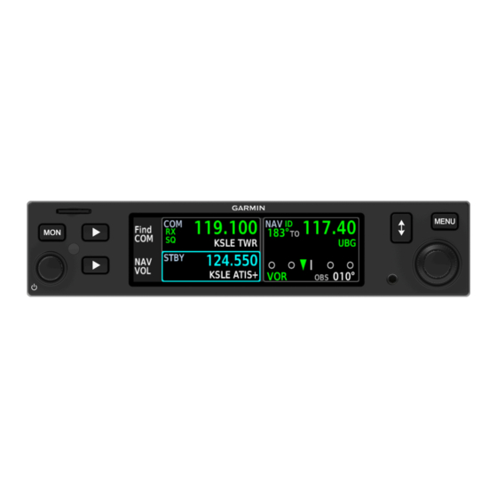
System at a Glance Overview GTR 205 and GNC 215 are panel-mount COM radio transceivers that employ a 3.2” high-resolution color liquid-crystal display. They comprise the Slimline series of 1.35” by 6.25” COM radio products. GNC 215 shown as typical. -
Page 15: Unit Features
System at a Glance Unit Features Features vary depending on model and unit configuration. GTR 205 GNC 215 COM TRANSCEIVER NAV/COM TRANSCEIVER • • 8.33 kHz or 25 kHz 8.33 kHz or 25 kHz channel spacing channel spacing • •... -
Page 16: Pilot Interface
System at a Glance Pilot Interface Bezel The bezel provides a combination of mechanical knobs and push-keys. Soft keys correspond to selectable features on the display screen. Display Screen microSD Card Slot Menu Key Inner & Outer Knobs Provides direct access Interface for loading Multipurpose dual to customization options... -
Page 17: Microsd Card Slot
When using a Macintosh computer to format the microSD card, Garmin recommends using the SD Memory Card Formatter application available as a download from SDcard.org. When running the application, use the Quick Format option. -
Page 18: Display Features
System at a Glance Display Features A high-resolution color LCD display provides onscreen controls that correspond to the mechanical knobs and push-keys on the bezel. Optional night vision capability (NVIS) is available with the purchase of a feature enablement. Soft Keys Selections change based on the active page or function. -
Page 19: Menu Tabs
System at a Glance Menu Tabs Tabs group information and related controls into individual panes. Contents may include scrolling lists, data fields, function keys, or a combination of controls. Tabs are located along the left side of the menu pane. Active Menu Selection Inactive Tabs... -
Page 20: Control Knobs
System at a Glance Control Knobs Outer Inner Dual Concentric Knob Volume/Power Knob Inner and outer control knobs offer A single volume knob controls the ability to select and modify audio volume for the COM radio data and settings. and powers the unit on/off. Pushing these knobs momentarily performs additional functions. -
Page 21: Knob Function Indicators
Outer Knob Single or Inner Knob Turn Only Turn & Push Indications include, but are not limited to: COM Standby Frequency Active, GTR 205 Available knob functions: • • Adjust COM radio Tune COM standby... - Page 22 System at a Glance Menu Active Find Frequency Active Available knob functions: Available knob functions: • • Scroll search categories Scroll menu tabs • • Select frequency Select list items • Add user frequency System Message List Active NAV Volume Active Available knob functions: Available knob functions: •...
- Page 23 System at a Glance KNOB FOCUS INDICATIONS A cyan border around the active feature window indicates changes in knob focus. This is useful when transitioning between different control modes. Text within the active window turns cyan to indicate that it is selectable.
-
Page 24: Knob Shortcuts
System at a Glance Knob Shortcuts For convenience, the unit allows you to access certain controls quickly via knob push. TUNE A COM FREQUENCY From the Home page: Pushing the dual concentric knob once switches knob focus between the COM radio and right side features (if available). - Page 25 System at a Glance FIND A COM FREQUENCY From any page or tab: Pushing and holding the dual concentric control knob for 1.5 seconds automatically displays frequency search options. The Select Frequency menu opens from the last viewed search result. 1.5 s Prior to activation, the “Hold for Find”...
- Page 26 If enabled, pushing the dual concentric knob once activates the timer function. Turn the outer knob to toggle between timer types. Turn the inner and outer knobs to specify a countdown time. Push knob to enter value. GTR 205 1-14 Pilot’s Guide...
- Page 27 System at a Glance SET AN OBS COURSE AVAILABLE WITH: GNC 215 From the Home page: If enabled, pushing the dual concentric knob once activates the OBS entry field. Turn the inner and outer knobs to set a course. Three-way Toggle Indication Locater bars work in conjunction with the inner control knob, providing a quick indication of current knob focus as you transition between multiple functions (e.g., COM standby...
- Page 28 System at a Glance Pushing the inner knob moves the locater through the available functions. The COM standby frequency window is active by default. COM Active OBS/Timer Active Push to activate OBS/timer control. Push to activate NAV frequency control. NAV Active Push to activate COM frequency control.
-
Page 29: Screenshots
System at a Glance Screenshots FEATURE REQUIREMENTS • A microSD card in the FAT32 format, with memory capacity between 8 GB and 32 GB Save images to a microSD card at any time using Screenshot. 1. Verify that a microSD card is present in the slot. 2. -
Page 30: Color Conventions
System at a Glance Color Conventions • Radio failure Green • Active radio frequency, function • Valid station ID (decoded from Morse code) • VOR/localizer data White • Active system message, mode • Current data and values • Menu options •... -
Page 31: Compatible Equipment
OPTIONAL LRUs maintenance and unit replacement. Optional LRUs may include compatible equipment from either G500/G600 Garmin or a third party G500(H)/G600/G700 TXi manufacturer. These vary by unit and installation type (VFR or IFR). GFC 500/600(H) Some LRUs provide features that... - Page 32 INTENTIONALLY LEFT BLANK 1-20 Pilot’s Guide 190-02766-02 Rev. A...
-
Page 33: Get Started
2 Get Started POWER UP THE UNIT ..................2-2 LOAD DATABASE ....................2-3 CUSTOMIZE PILOT SETTINGS ..............2-12 VIEW SYSTEM INFORMATION..............2-17... -
Page 34: Power Up The Unit
Bezel key backlight momentarily illuminates • Navigation database automatically updates if a newer version is available Splash Page Garmin logo displays as the unit checks for an available database update. Read more about database update methods in Load Database. Power Off the Unit WARNING Never attempt to power off the unit while airborne unless operational procedures dictate. -
Page 35: Load Database
This system uses the Navigation purchase individual databases or database database for frequency related packages, go to flyGarmin.com. information (Garmin or Jeppesen). Active and Standby Databases The unit uses two types of databases. Both transfer to the unit’s internal storage. Active Database Standby Database •... - Page 36 Get Started DATABASE TRANSFER & ACTIVATION The Navigation database automatically transfers from the microSD card to the unit’s internal Standby storage if it is newer than the database currently in standby. Total transfer time depends on the microSD card type. Activation of the standby database is required to complete the update.
-
Page 37: Load Database From A Microsd Card
Get Started Load Database from a microSD Card NOTE The unit supports microSD cards in the FAT32 format only, with capacities ranging between 8 GB and 32 GB. The unit stores all databases it receives in its internal storage. After a database updates, the microSD card is no longer required. -
Page 38: Automatic Updates
Get Started Automatic Updates Updates occur during power up when a Automatic updates occur newer version of the database is available. when: The same process occurs when you load a new database for the first time. • A newer database is detected on the microSD card or in the internal Standby storage... -
Page 39: Database Errors
Get Started Database Errors If a database error occurs: • An advisory appears in the message list • Details regarding the state of the database display on the appropriate information tab Aviation Database Errors Visit flyGarmin.com to report any discrepancies in database information. -
Page 40: Revert To Previous Database Version
Get Started Revert to Previous Database Version Updating a database does not overwrite its previous version. Once the update process completes, the previously active version of the database transfers to the unit’s internal Standby storage. In the event that an automatic update is undesirable, you can revert to the previous version using the manual update feature. -
Page 41: View Database Information
Get Started View Database Information WHERE TO FIND IT During normal operation, you can view information about active and standby databases Menu from the Database Information page. MENU > System > Database System Database Select the appropriate menu tab to view information about active and standby databases. -
Page 42: Standby Database
Get Started Standby Database Selecting Standby displays information about the database that is not currently in use by the system. The previously installed database also appears here once an update completes. “Standby database OK” appears at the bottom of the Standby tab whenever a valid database is present on the installed microSD card or in the internal memory. -
Page 43: Understand Database Effective Cycles
Get Started Understand Database Effective Cycles DATABASE EFFECTIVE STATUS • Effective during a specific period • Database with Unit determines database status using the current date specified and time from GPS effective dates • Automatic activation occurs on the effective date during unit power cycle NO VALID DATABASE A message informs you when no... -
Page 44: Customize Pilot Settings
Access database information and update/sync options System Tab • View system messages • View system information and COM status GTR 205 only. GNC 215 only. CDI and flight timer functions are mutually exclusive; enabling one automatically disables the other. 2-12 Pilot’s Guide 190-02766-02 Rev. A... -
Page 45: Customize Display Layout
Get Started Customize Display Layout AVAILABLE WITH: GNC 215 Choose any combination of features for display in the active and/or standby areas of the NAV radio. Options are accessible from the Display tab (MENU > Display). Knob focus is set to Off by default. To enable a display feature, select it from the menu. - Page 46 Get Started From Adds decoded “to” bearing Adds decoded “from” radial information to the active NAV information to the active NAV frequency. frequency. “To” and “from” information includes distance to station when an internal database and GPS source are present. Adds an active timer to the Replaces NAV STBY window lower right of the display.
-
Page 47: Customize Unit Settings
Get Started Customize Unit Settings WHERE TO FIND IT Customize the display unit settings. Selecting Units opens a menu of available unit types. Menu MENU > Setup > Units Setup Units To specify unit type: 1. Review the current unit selections. -
Page 48: Adjust Display Brightness
Installer configured curves determine the amount of change in brightness that occurs in response to a control adjustment. If brightness control is not satisfactory, contact a Garmin dealer to adjust the lighting curves. 2-16 Pilot’s Guide 190-02766-02 Rev. A... -
Page 49: View System Information
Get Started View System Information WHERE TO FIND IT View information specific to the unit and its software. Menu System System Info Refer here when contacting customer service. System Info • Serial number • System ID • Main software version 190-02766-02 Rev. A Pilot’s Guide 2-17... - Page 50 INTENTIONALLY LEFT BLANK 2-18 Pilot’s Guide 190-02766-02 Rev. A...
-
Page 51: Com
3 COM SET UP COM RADIO.....................3-2 ADJUST COM RADIO VOLUME & SQUELCH...........3-5 TUNE A COM FREQUENCY ................3-6 MONITOR A COM FREQUENCY..............3-9 FIND A COM FREQUENCY ................3-10 CREATE COM USER FREQUENCIES............3-16 VIEW COM STATUS ................... 3-19 RESPOND TO A COM ALERT ................ 3-20... -
Page 52: Set Up Com Radio
Set Up COM Radio WHERE TO FIND IT VHF COM radio customization options are accessible via the Setup tab. Menu MENU > Setup > COM Settings Setup COM Settings COM RADIO SETTINGS Set transceiver squelch to Auto or adjust the threshold COM Squelch manually. -
Page 53: Set Com Channel Spacing
Set COM Channel Spacing The unit supports channel tuning for both 8.33 kHz and 25 kHz channels within radio-frequency range. Channel spacing is set to 25.0 kHz by default. Turning the inner knob toggles the transceiver channel spacing between 8.33 kHz and 25.0 kHz. 25.0 kHz 8.33 kHz 8.33 kHz step configuration... -
Page 54: Adjust Sidetone Volume Offset
Adjust Sidetone Volume Offset FEATURE LIMITATIONS • Availability dependent upon configuration • Offset range: +/-25% of total COM audio volume range Numeric If the unit is wired for audio output, Offset Value set the sidetone volume offset to the preferred level. By default, the offset value is set to zero percent. -
Page 55: Adjust Com Radio Volume & Squelch
Adjust COM Radio Volume & Squelch Percent of Relative Volume Max Volume Indicator Adjust radio volume with the small knob according to your preference. The unit retains volume settings over power cycles. Open Squelch Push the volume/squelch knob to override the automatic squelch function. -
Page 56: Tune A Com Frequency
Tune a COM Frequency Communication frequencies are split between two selectable windows: • The upper window presents the active COM radio frequency. This is the frequency currently in use for transmit and receive operations. • The lower window presents the standby radio frequency. This frequency may be set and activated at any time. -
Page 57: Tune A Standby Frequency
Tune a Standby Frequency The dual concentric control knob allows you to enter a standby frequency. Pushing and holding the dual concentric control knob for 0.5 seconds automatically displays frequency search options. The selected STBY window turns cyan when you use the control knob to change the standby COM frequency. -
Page 58: Transfer Frequency To Active (Flip-Flop)
Transfer Frequency to Active (Flip-Flop) The transfer (or flip-flop) function allows you to swap the active and standby frequency values. Before After Pilot’s Guide 190-02766-02 Rev. A... -
Page 59: Monitor A Com Frequency
Monitor a COM Frequency Enabling monitor mode allows you to listen to the standby frequency while the unit continues monitoring the active COM channel. When the COM active frequency receives a signal, the unit automatically switches back to the active frequency. Once activity on the COM active channel ceases, the unit returns to listening to the standby frequency. -
Page 60: Find A Com Frequency
Find a COM Frequency Find and select a standby COM frequency from a list of available database frequencies. Pushing the Find COM soft key while the COM radio is active provides access to multiple search options. Each category displays a list of selectable identifiers based on specific criteria. FEATURE REQUIREMENTS •... - Page 61 SEARCH RESULTS Each frequency includes general information about the associated waypoint. Bearing Waypoint & Distance Identifier & Facility Name Nearest airports include bearing and distance to field information based on GPS data. MULTIPLE FREQUENCIES A selector appears when more than one frequency type is available at the indicated identifier.
- Page 62 FREQUENCY SEARCH ERRORS Search errors may display if any one of the following conditions exist. Nearest Frequency Search Options The unit is configured for GPS The unit is configured for GPS but is not receiving a position. but no database is present. Database Search Option No database is present.
-
Page 63: Reverse Frequency Look-Up
Reverse Frequency Look-up This function automatically displays the facility identifier and frequency type for active and standby frequencies. The unit verifies the displayed frequency against the database at least once per minute. Facility Identifier “+” denotes more than one type associated with the frequency. - Page 64 DATA SIZE & POSITION The size and location of Reverse Frequency Look-up text is dependent upon the status of right side features. Default View Text is larger for easier viewing. Timer Enabled Text shifts beneath the frequency value when you enable right side features.
-
Page 65: Remote Frequency Selection
Remote Frequency Selection FEATURE LIMITATIONS • Availability dependent upon configuration On units configured for remote frequency recall, COM user frequencies are selectable via a remote switch. • Pressing the switch once loads the next user frequency into the STBY window •... -
Page 66: Create Com User Frequencies
Create COM User Frequencies FEATURE LIMITATIONS • Names may be up to 10 characters in length • Maximum number of 20 user frequencies Add a frequency to the user frequency list. Controls are accessible via the Select Frequency menu. 1. Open the Select Frequency menu. -
Page 67: Edit A Com User Frequency
Edit a COM User Frequency Modify an existing user frequency. Selecting a user frequency gives you the EDIT option. 1. Select the user frequency from the list. 2. Push the Edit soft key. 3. Modify the current frequency name and/or value using the dual concentric knob. -
Page 68: Delete A Com User Frequency
Delete a COM User Frequency Selecting Delete opens a confirmation page. From here you can delete the selected user frequency or all user frequencies in the list. Confirm the request to remove the selected user frequency from the list. Selecting Delete All Frequencies opens a pop-up. Confirming the request removes all COM user frequencies from the list. -
Page 69: View Com Status
View COM Status WHERE TO FIND IT View COM radio transmit voltage and received noise. This information is accessible via the Menu System tab. System MENU > System > COM Status COM Status This page is for reference only. Information includes: •... -
Page 70: Respond To A Com Alert
Respond to a COM Alert Radio failures are indicated by one or more of the following: • Red “X” displays over the COM radio control • Advisory message alerts • COM control options are not available COM radio fail annunciations are designed to be immediately recognizable. For information regarding pilot response to a COM radio failure, consult the AFMS. -
Page 71: Nav
GNC 215 ONLY 4 NAV ADJUST NAV RADIO VOLUME ...............4-2 ACTIVATE NAV IDENT ..................4-2 TUNE A NAV FREQUENCY................4-3 MONITOR A NAV FREQUENCY..............4-6 FIND A NAV FREQUENCY .................4-7 VIEW NAVIGATION DATA.................4-9 SPECIFY AN OBS COURSE................4-11 RESPOND TO A NAV ALERT ................. 4-13... -
Page 72: Adjust Nav Radio Volume
Adjust NAV Radio Volume Pushing the NAV VOL soft key while the NAV or COM radio is selected provides access to volume controls. Adjust radio volume with the inner and outer control knobs according to your preference. Percent of Relative Volume Max Volume Indicator You can adjust the volume by increments of ten... -
Page 73: Tune A Nav Frequency
Tune a NAV Frequency Navigation frequency tuning, transfer, and selection functions are identical to those used for communication frequencies. NAV STATUS INDICATIONS Frequency The unit automatically decodes Morse code Identifier from and displays the Ident for the active frequency Morse Code above it. - Page 74 Received from Database & GPS Received from Morse Code Station information appears The identifier turns green when white when the identifier is a valid ID is decoded from inferred from the database Morse code. and current location. Custom User NAV Frequencies User stored NAV frequencies may display in the absence of a remote source or internal...
- Page 75 STANDBY NAV FREQUENCY ENTRY To change the standby NAV frequency: Active NAV Frequency 1. Activate the standby NAV frequency window by selecting Home, then pushing the dual concentric control knob once or twice depending on pilot settings. Upon selection, the standby NAV frequency window remains active for approximately 30 seconds.
-
Page 76: Monitor A Nav Frequency
Monitor a NAV Frequency Pushing the MON key while the NAV standby frequency is selected allows you to listen to the standby frequency while the unit continues monitoring the active NAV channel. Morse ID During monitor mode: Unavailable • A gray “ID” with strike-through indicates that Morse ID is unavailable on the active... -
Page 77: Find A Nav Frequency
Find a NAV Frequency Find and select a standby NAV frequency from a list of available database frequencies. Pushing the Find NAV soft key while the NAV radio is selected provides access to multiple search options. Each category displays a list of selectable identifiers based on specific criteria. FEATURE REQUIREMENTS •... - Page 78 FREQUENCY SEARCH ERRORS Search errors may display if any one of the following conditions exist. Nearest Frequency Search Options The unit is configured for GPS The unit is configured for GPS but is not receiving a position. but no database is present. Database Search Option No database is present.
-
Page 79: View Navigation Data
View Navigation Data Depending on configuration, you may Navigation data include: view supplemental navigation data in the • Decoded From radial and active and standby areas of the NAV radio. To bearing Data options are selectable from the • Distance to station Display tab (MENU >... -
Page 80: Cdi
When enabled, a CDI replaces the NAV STBY window. It appears between the active and standby windows when you are actively monitoring the NAV standby frequency. Active NAV Frequency The CDI presents a sliding lateral Frequency Look-up deviation indicator on a horizontal Window Result scale. -
Page 81: Specify An Obs Course
Specify an OBS Course The unit allows manual entry of the OBS selected course in the absence of an external CDI/HSI selected course input. Specify a selected course using the dual concentric knob. Exit entry mode by doing one of the following: •... - Page 82 OBS SOURCE LOST A message informs you when GNC 215 loses selected course input from the external NAV indicator. When this occurs, you may select OBS. 4-12 Pilot’s Guide 190-02766-02 Rev. A...
-
Page 83: Respond To A Nav Alert
Respond to a NAV Alert Radio failures are indicated by one or more of the following: • Red “X” displays over the NAV radio control • Advisory message alerts • NAV control options are not available NAV radio fail annunciations are designed to be immediately recognizable. Use an alternate method of navigation in response to a NAV radio failure. - Page 84 INTENTIONALLY LEFT BLANK 4-14 Pilot’s Guide 190-02766-02 Rev. A...
-
Page 85: Timers
5 Timers ENABLE & VIEW TIMERS..................5-2 SET COUNTDOWN TIMER ................5-4 SET COUNT UP TIMER..................5-4... -
Page 86: Enable & View Timers
Timers Enable & View Timers Set a generic timer for general timing needs. Two stopwatch style counters allow you to count up or count down. WHERE TO FIND IT Enable timers by selecting the Timer function on the Display tab. MENU MENU >... - Page 87 Timers TIMER CONTROLS ACTION SOFT KEY Basic timer functions are accessible via dual concentric knob push. Cancel start value Cancel Control options change according to entry the current timer state. Start timer Start Stop timer Stop Reset timer Reset Countdown timer only. 190-02766-02 Rev.
-
Page 88: Set Countdown Timer
Timers Set Countdown Timer The unit retains the most recent count down value following a power cycle. 1. Set direction to count down (CNT DN) using the outer control knob. 2. Specify countdown time using the inner and outer control knobs. •... -
Page 89: Messages
6 Messages VIEW SYSTEM MESSAGES .................6-2... -
Page 90: View System Messages
Messages View System Messages WHERE TO FIND IT Advisories are system-related messages relative to the display. A list of active advisories is viewable from the System tab: Menu MENU > System > Messages System You can open the list directly by pushing the Messages MSG soft key when an active message is present. -
Page 91: Com Radio Advisories
Messages COM Radio Advisories ADVISORY CONDITION CORRECTIVE ACTION COM radio is reporting COM radio needs that it requires service. Cycle radio power. service. Functionality may be Contact dealer for service. unavailable. • Decrease length of COM COM radio is in overtemp transmissions. - Page 92 Messages ADVISORY CONDITION CORRECTIVE ACTION Unit detects the specified switch is active for 30 seconds. The input is ignored as a result. Radio stops transmitting. Includes: • Verify that the switch is not Standby monitor COM <name> stuck. Contact dealer for remote switch switch is stuck.
-
Page 93: Database Advisories
Database Advisories ADVISORY CONDITION CORRECTIVE ACTION Re-download and install Active DB corrupt. The active database is database. Contact a Garmin Remove or replace. unavailable or corrupt. dealer for support. The standby database Database will update completed transfer and is on next power cycle. -
Page 94: Pilot Specified Advisories
Messages Pilot Specified Advisories These advisories display when the associated timer expires or reaches a preset value. They are informational only. Other than acknowledging the message, no action is necessary. ADVISORY CONDITION Timer has expired. Countdown timer is reaching zero. Pilot’s Guide 190-02766-02 Rev. -
Page 95: System Hardware Advisories
Messages System Hardware Advisories ADVISORY CONDITION CORRECTIVE ACTION The unit cannot Configuration communicate with its module needs configuration module. Contact dealer for service. service. Unit configuration may still be valid. Unit temperature exceeds Decrease cabin temperature Unit over the over temperature and increase cabin airflow temperature. - Page 96 Messages ADVISORY CONDITION CORRECTIVE ACTION System detects the indicated bezel key is depressed for at least 30 seconds. It will now ignore this input. Push the indicated key again. Includes: <Name> key is stuck. If it remains stuck, contact • Bottom soft key dealer for service.
-
Page 97: Vloc/Gs Advisories
Messages VLOC/GS Advisories AVAILABLE WITH: GNC 215 ADVISORY CONDITION CORRECTIVE ACTION Verify glideslope deviation indications with another source and cross-check final Glideslope board is approach fix crossing altitude. Glideslope receiver reporting that it requires If another source is not needs service. service. - Page 98 INTENTIONALLY LEFT BLANK 6-10 Pilot’s Guide 190-02766-02 Rev. A...
-
Page 99: Glossary
Automatic Terminal Information Service Course Deviation Indicator Database Distance Measuring Equipment Federal Aviation Administration Federal Communication Commission FREQ Frequency Flight Service Station Garmin Flight Controller Garmin NAV/COM Global Positioning System Glideslope Garmin Transceiver Radio HSDB High Speed Data Bus Horizontal Situation Indicator... - Page 100 Glossary Instrument Flight Rules Instrument Landing System Liquid Crystal Display Letter of Authorization Localizer Line Replaceable Unit Message Navigation NAVAID Navigation Aid NVIS Night Vision Imaging System Omni Bearing Selector Radius to Fix Receive, Receiver Secure Digital STBY Standby True To/From Transmit Pilot’s Guide...
- Page 101 Glossary Visual Flight Rules Very High Frequency VLOC VOR/Localizer Very High Frequency Omnidirectional Range Weather 190-02766-02 Rev. A Pilot’s Guide...
- Page 102 INTENTIONALLY LEFT BLANK Pilot’s Guide 190-02766-02 Rev. A...
-
Page 103: Regulatory Information
8 Regulatory Information COMPLIANCE......................8-2 SOFTWARE LICENSE AGREEMENT ..............8-3... -
Page 104: Compliance
2014/53/EU. The full text of the EU declaration of conformity is available at the following internet address: www.garmin.com/compliance. UK Declaration of Conformity Hereby, Garmin declares that this product is in compliance with the relevant statutory requirements. The full text of the declaration of conformity is available at the following internet address: www.garmin.com/compliance. -
Page 105: Software License Agreement
AND CONDITIONS OF THE FOLLOWING SOFTWARE LICENSE AGREEMENT. PLEASE READ THIS AGREEMENT CAREFULLY. Garmin Ltd. and its subsidiaries (“Garmin”) grants you a limited license to use the software embedded in the Garmin Product (the “Software”) in binary executable form in the normal operation of the Garmin Product. - Page 106 INTENTIONALLY LEFT BLANK Pilot’s Guide 190-02766-02 Rev. A...
- Page 108 190-02766-02 Rev. A...
Need help?
Do you have a question about the GTR 205 and is the answer not in the manual?
Questions and answers